EP1974331B1 - Affichage d'une vision de synthese tridimensionnelle en temps reel de donnees de terrain validee par capteur - Google Patents
Affichage d'une vision de synthese tridimensionnelle en temps reel de donnees de terrain validee par capteur Download PDFInfo
- Publication number
- EP1974331B1 EP1974331B1 EP07835677.1A EP07835677A EP1974331B1 EP 1974331 B1 EP1974331 B1 EP 1974331B1 EP 07835677 A EP07835677 A EP 07835677A EP 1974331 B1 EP1974331 B1 EP 1974331B1
- Authority
- EP
- European Patent Office
- Prior art keywords
- data
- terrain
- sensor
- database
- grid
- Prior art date
- Legal status (The legal status is an assumption and is not a legal conclusion. Google has not performed a legal analysis and makes no representation as to the accuracy of the status listed.)
- Active
Links
Images


Classifications
-
- G—PHYSICS
- G01—MEASURING; TESTING
- G01C—MEASURING DISTANCES, LEVELS OR BEARINGS; SURVEYING; NAVIGATION; GYROSCOPIC INSTRUMENTS; PHOTOGRAMMETRY OR VIDEOGRAMMETRY
- G01C23/00—Combined instruments indicating more than one navigational value, e.g. for aircraft; Combined measuring devices for measuring two or more variables of movement, e.g. distance, speed or acceleration
-
- G—PHYSICS
- G06—COMPUTING OR CALCULATING; COUNTING
- G06T—IMAGE DATA PROCESSING OR GENERATION, IN GENERAL
- G06T17/00—Three-dimensional [3D] modelling for computer graphics
- G06T17/05—Geographic models
-
- G—PHYSICS
- G06—COMPUTING OR CALCULATING; COUNTING
- G06T—IMAGE DATA PROCESSING OR GENERATION, IN GENERAL
- G06T3/00—Geometric image transformations in the plane of the image
- G06T3/40—Scaling of whole images or parts thereof, e.g. expanding or contracting
- G06T3/4007—Scaling of whole images or parts thereof, e.g. expanding or contracting based on interpolation, e.g. bilinear interpolation
Definitions
- the invention relates generally to Synthetic Vision systems. In particular it relates to real-time updating and three-dimensional visualization of Synthetic Vision terrain data.
- GPS global positioning system
- Radar altimetry is an example of an active sensor for detecting height above terrain.
- a radar altimeter emits radio waves and times how long they take to return to the aircraft after reflecting off the ground. The time delay is converted into distance.
- Radar altimeters are often used as a numerical aid during a precision approach to a runway. Radar altimeters have limited range, generally point straight down, and offer only one data point for each aircraft position. Radar, lidar and other types of ranging sensors can give a pilot a reasonable "picture" of objects in his immediate vicinity. However, skill and experience are needed to interpret radar images.
- Synthetic Vision a three-dimensional perspective view of the outside world rendered on artificial display. Synthetic Vision uses computer graphics to show terrain and man-made objects in the same position, orientation and perspective as they would appear if one were looking at them on a bright, clear day.
- the Synthetic Vision system has to "know” where the terrain is and also where the aircraft is.
- GPS sensors and microelectromechanical gyroscopes and accelerometers are often used to obtain the position and spatial orientation ("attitude") of an aircraft.
- the location of terrain and objects on the ground is stored in a database that contains latitude, longitude and altitude (e.g. height above mean sea level) information for the ground, buildings, towers, etc.
- latitude, longitude and altitude e.g. height above mean sea level
- SRTM Shuttle Radar Topography Mission
- NASA has released version 2 of the SRTM digital topographic data (also known as the "finished" version).
- the new data set is sampled at 3 arc-seconds, which is 1/1200th of a degree of latitude and longitude, or about 90 meters (295 feet).
- Researcher Maqart Uijt de Haag has disclosed a database validation system that involves comparing radar altimeter measurements, GPS altitude and a terrain database to find places where the database is inaccurate or unreliable.
- the altitude of the airplane is measured by GPS and the radar altitude. The difference in those two altitudes should be equal to the terrain elevation stored in the database. If the system finds a significant difference then a warning signal is sent to the pilot.
- This approach serves the function of monitoring the accuracy and reliability of the terrain database, but it has shortcomings of its own. (See, for example: M. Uijt de Haag et al., "Terrain Database Integrity Monitoring for Synthetic Vision Systems", IEEE Transactions on Aerospace and Electronic Systems, vol. 41, p.
- radar any kind of ranging sensor.
- lidar any kind of ranging sensor.
- Such a system can display images of the outside world as built up from real-time ranging measurements.
- radar systems are helpful, they have fundamental limitations. First of all, radar shows an image of what it sees at the moment, but it doesn't remember what it saw before. The radar transmitter must be pointed in the direction one wants to see. Also, radar does not see around a corner in a valley, or over a ridge. Finally, radar necessarily involves the transmission of high power electromagnetic energy which may be detected by an enemy; or worse provides a homing signal for enemy weapons.
- US2005/099433A1 discloses a system and method for mounting sensors and cleaning sensor apertures for out-the-window displays. Multiple sensors capture images representing scenery outside an aircraft for use within a visual display system. Continuous images representing scenery outside the aircraft are provided through an operator display.
- the present invention provides a terrain display system according to claim 1 of the appended claims.
- the invention further provides a method for updating a terrain database, according to claim 10 of the appended claims.
- the system provides a synthetic view of terrain and obstacles in the vicinity of a moving vehicle.
- the synthetic view is a computer rendering, in three-dimensional perspective, of objects in a terrain database.
- the database is updated in real-time in response to data obtained by a ranging sensor.
- the database may be stored and shared with other vehicles.
- the synthetic view displays terrain around the vehicle in the same position, orientation and perspective in which it would appear on a bright, clear day (i.e. in the absence of any restrictions to vision).
- the synthetic view may therefore be used in darkness or low-visibility conditions to replace one's normal vision with Synthetic Vision.
- the location of terrain and obstacles is stored in a computer database.
- a Synthetic Vision system mounted in a helicopter provides the helicopter pilot with a synthetic view of the helicopter's surroundings.
- a radar system in the helicopter is integrated with the Synthetic Vision system to update a terrain or obstacle database in real-time.
- a Synthetic Vision system mounted in a submarine provides the helmsman with a synthetic view of the submarine's surroundings.
- a sonar system in the submarine is integrated with the Synthetic Vision system to update a sea floor or obstacle database in real-time.
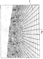
- Fig. 1 shows a Synthetic Vision terrain grid displayed in three-dimensional perspective.
- the grid image 105 represents, as an example, terrain below and in front of a helicopter.
- the terrain in the foreground of the image is relatively flat, perhaps representing a plain or desert area, while hills appear in the distance.
- the terrain grid shown in Fig. 1 is a synthetic representation of the actual "out the helicopter window" view one would have of the corresponding area on earth.
- the image may be displayed on a graphic display in a helicopter cockpit. Despite its apparent simplicity there are several features of the displayed image that are important to note.
- the data itself is a large collection of numerical values that is stored by any one or a combination of conventional means such as dynamic random access computer memory, flash memory, magnetic recording, etc.
- the image on the other hand is the representation of the data in graphical form for easy human interpretation.
- the data represented in the image in Fig. 1 comprises elevation information for an array of positions on Earth that are laid out in a grid.
- Each point in the grid i.e. each place where grid lines cross, has latitude, longitude and altitude coordinates. It is possible to associate additional variables, such as temperature or update time, with the grid points if needed.
- grid illustrated in Fig. 1 is rectangular, other layouts such as triangular, hexagonal, etc., may be used with the methods disclosed herein. Irregular grids, such as triangular irregular networks, are desirable for situations where the area density of grid points to varies from place to place. A grid could have more points in areas where higher resolution sensor data is available, for example.
- grid means an arrangement of points; “grid” does not necessarily imply a regularly spaced array.
- Real world terrain features such as peaks and valleys may occur anywhere.
- the grid points shown in Fig. 1 therefore are necessarily the result of interpolation of data collected at arbitrary locations between grid points.
- the interpolation of randomly spaced data to fit a grid results in some information loss.
- a grid cannot represent terrain fluctuations that occur at spatial frequencies greater than the reciprocal of twice the grid spacing.
- a grid is scalable. No matter how many times new terrain information is added by interpolation, the number of grid points remains constant. This property is important in practice because it keeps the problem of rendering the grid data computationally tractable.
- Fig. 1 Visual characteristics of the image in Fig. 1 contribute to making an easily viewable and interpretable display of grid data.
- the perspective view is inherently intuitive to interpret. It duplicates the view that one sees with normal vision.
- solid grid lines (contrasted with dashed lines, for example) contribute to making a display easy to understand.
- grid lines in the foreground are rendered as sharp lines while those in the distance are blurred. This anti-aliasing is necessary because the distant lines should be represented by lines on a display that are less than one display pixel wide. Attempts to represent thin lines by duty cycle modulation of pixels results in undesirable and visually grating artifacts. Intentional blurring on the other hand conveys the natural sensation of loss of detail in the distance.
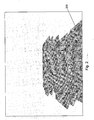
- Fig. 2 shows a three-dimensional perspective image of part of a Synthetic Vision terrain grid that has been validated by sensor measurement.
- the quality of terrain databases for Synthetic Vision is improving, the data is not presently reliable enough to use for close-in collision avoidance.
- a database may not include changes to terrain features that have occurred after the database was created. Therefore a Synthetic Vision system must be able to validate terrain data whenever possible. Details of how sensor measurements are used to update terrain data in real time are discussed below.
- terrain grid image 205 represents a section of Synthetic Vision terrain data that has been validated. Typically this means that the system has high confidence that the data represents the position of actual terrain faithfully.
- the data could be validated by sensor measurements such as onboard radar returns. Or it could have been validated by another vehicle and received via a data link. Or it could have been validated by people on the ground transmitting position and elevation data. "Validated” may be extended to mean simply "from a different source” or "obtained at a different time” than existing database information. It is information that the system designer wants to point out to the user.
- validated data is brought to attention by displaying it differently from other data.
- One of the most effective ways to distinguish validated data is to show it in a distinctive color. Often validated data is shown in green, for example, to convey a sense of safety and security.
- brightness and texture are qualities that are effective to distinguish validate data. Validated data is more easily interpreted if it is brighter than its surroundings and if it has a texture. When color separation is not available, for example on a monochrome display, texture and brightness can still be effective visual cues.
- grid image 205 has a distinctive texture and is also rendered brighter (on paper brighter is represented by more ink used) than the a priori image of Fig. 1 .
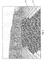
- FIG. 3 shows a three-dimensional perspective image of a Synthetic Vision terrain grid.
- Fig. 3 part of the image has been validated by sensor measurement.
- the plain grid 305 represents data that has not been validated, while the textured and colored grid 310 represents validated data. It is intuitively clear that something is different about the validated area in Fig. 3 compared to the plain area, and a pilot using a display showing the image would not have to think twice or be told that he could rely on the validated areas of the scene with higher confidence than the plain areas.
- the validated area 310 may show that perhaps unexpected terrain has been detected. Intuitively the significant revision to the picture provided by the validated data throws into question the reliability of the rest of the plain data. In contrast, if the elevation of the validated terrain is little changed from the previous data, then the opposite effect may occur; the plain area may be viewed with more confidence.
- a Synthetic Vision system coupled to a database that is updated and validated in real-time effectively performs cartography on the fly.
- a ranging sensor When used as a source for validation data, it can "paint" a detailed terrain map on top of old or less reliable information.
- Synthetic Vision display shows only two validation states of data, validated and not, is very effective.
- a scene might comprise pre-existing terrain data, validated terrain, and warning areas.
- warning areas might be depicted in an alert color such as red or yellow.
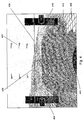
- Fig. 4 shows a three-dimensional perspective image of a Synthetic Vision terrain grid (part of which has been validated by sensor measurement) with vehicle state symbology superimposed.
- 405 is an area of pre-existing terrain data
- 410 is an area of validated terrain data
- symbols 415, 420, 425, 430, 435, and 440 provide, in generic terms, vehicle state data.
- the symbols shown in Fig. 4 are appropriate to a helicopter application.
- symbol 415 is an altitude readout (with an accompanying radar altimeter readout) while symbol 420 shows airspeed.
- symbol 420 shows airspeed.
- Symbol 425 is part of a pitch ladder
- 430 is a horizon line
- 440 is a heading indicator.
- Symbol 435 represents the pitch attitude of the helicopter; in the figure it is five degrees nose down for forward flight.
- the combination of vehicle state symbology with the synthetic view of the outside is analogous to the view through a "head - up" display of the real outside world.
- the displayed image could be further enhanced with navigational data.
- numerical distance to a planned fix could be displayed or more complex information such as "highway-in-the-sky" guidance could be provided.
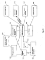
- Fig. 5 is a block diagram of the components of a terrain display system.
- This processor combines data from vehicle position and attitude sensors 510, terrain database 515, and ranging sensor(s) 520 to create an image rendered on display 525.
- item 530 is a storage unit for sensor and state data; 535 is a source of vehicle state information such as airspeed.
- Block 540 represents controls for the fusion and graphics processor such as controls to turn radar validation on and off, or to turn Synthetic Vision database terrain on and off. These controls may also adjust the relative brightness of synthetic and validated terrain.
- Display controls 545 include adjustments such as brightness and zoom.
- Data-links 550 and 555 transmit and receive, respectively, data to and from other vehicles and users represented in block 560.
- Fusion and graphics processor (“the processor") 505 may be implemented in off-the-shelf or custom computer processing hardware.
- the processor performs the algorithm outlined in Fig. 6 as described below. In most cases the processor interacts with the other block components via one-directional information flow. For example, ranging sensor(s) 520, position and attitude sensors 510, vehicle state information for symbology 535 and fusion system controls 540 all send information to the processor.
- the processor similarly sends information to display 525.
- the processor both receives terrain data from the database and sends updated data to the database as it is created.
- the database is a dynamic entity, the contents of which are constantly changing.
- Database 515 may comprise both low and high access speed memory devices. For example, it can include magnetic disk storage as well as random access memory (RAM). Information for a large region can be moved from disk to RAM as needed. The database is updated in response to information obtained by ranging sensor(s) 520.
- RAM random access memory
- Ranging sensor(s) 520 may include radar, lidar, sonar, or other technologies.
- a ranging sensor provides the range to the nearest obstacle in a particular direction (i.e. azimuth, elevation, radius).
- a practical ranging sensor emits a beam of finite angular width; thus the farther the beam travels the more area it encompasses perpendicular to the direction of travel. Long distance measurements cover more area than close measurements.
- the ranging sensor usually includes a scanning system so that an image can be built up from point measurements.
- the database may also be updated by data received via datalink 555.
- helicopters returning from a mission may transmit recent database information to helicopters leaving to go to the same place.
- Position and attitude sensors 510 provide position and orientation data to processor 505.
- This sensor suite may include GPS receivers, heading sensors, gyroscopes and accelerometers among other sensors.
- the sensor data may also be sent to outbound data-link 550 and data storage unit 530.
- Storage unit 530 may comprise RAM, disk or other memory devices.
- Control blocks 540 and 545 comprise all adjustments and inputs that a user can present to the processor and the display respectively.
- Fig. 6 is a flow chart for a terrain fusion and display system.
- Fig. 6 shows steps 605 - 650 which the processor follows; however, these steps are not always performed in the order indicated. It is easiest to present an algorithm in loop form as shown in Fig. 6 , but it may also be implemented in an interrupt-driven scheme where the loop elements are accomplished as required rather than sequentially.
- step 605 is the initialization of the display unit; in step 610 communications with sensors and state data providers are initialized. Local area synthetic terrain data is loaded into the processor in step 615.
- step 620 the processor receives new state data. In other words this is the step where the processor gets the latest information on position and attitude of the vehicle (e.g. a helicopter) in which the system is mounted.
- Attitude as well as position is needed because the perspective view of the surrounding terrain depends upon how the vehicle is oriented. This is in contrast to a simple map system where only position is necessary.
- Ranging sensor measurements for example radar information
- These measurements include range (i.e. distance) information and the azimuth and elevation angles that the sensor was pointing at the time of the measurement. These angles and the range are measured with respect to the vehicle.
- range i.e. distance
- azimuth, elevation, range To compare these data with database data the (azimuth, elevation, range) triad must be transformed from vehicle-relative coordinates to global-relative coordinates (latitude, longitude, altitude). This process is referred to as a [III][II][I] or Yaw, Pitch, Roll coordinate transform, the principles of which are well known in the art.
- step 635 the sensor information is compared with terrain database data.
- the processor determines which topography grid points contained in the database should be updated.
- the updating operation includes saving updated database information. Further details of how the sensor data is interpolated to update the elevation of grid points are provided in connection with Figs. 7 and 8 .
- the updated terrain information is rendered into a computer graphic image in step 640. This operation encompasses all the graphics rendering calculations. Finally, additional symbology such as attitude and heading information is overlaid onto the image in step 645. At this point the processor checks to see if further operation is required. If it is, the process just described repeats itself starting at step 620; otherwise the processor stops in step 650.
- a regular or irregular network of grid points in a synthetic terrain view is a useful feature because it forms a scalable system.
- new terrain elevation data for an arbitrary position on the ground is obtained by a ranging sensor, that data is used to adjust the height of nearby grid points.
- the number of grid points and their lateral locations do not change however. Therefore, no matter how much new terrain elevation data arrives, the number of computations required to display the synthetic view does not change.
- Incoming ranging sensor data can be incorporated into a grid terrain database through interpolation with an influence function.
- the influence function specifies how much effect new elevation data received for an arbitrary location has on nearby grid points.
- the influence function may be related to the sensor's beamwidth and/or be appropriately modified to account for other system requirements, such as, for example, database grid structure and spacing.
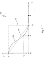
- Fig. 7 shows a graph 705 of various influence functions.
- influence /
- r is plotted versus radius, r .
- Three influence functions 710, 715 and 720 are shown.
- radius r 0 and also the radii for points Y and Z (discussed below) are marked.
- I axis 1 (unit influence) and influence value I Y are marked.
- Influence functions 710, 715 and 720 share the properties:
- Function 720 could be a cubic approximation to a Gaussian function, for example.
- FIG. 8 shows a schematic illustration of a synthetic terrain grid 805 with a graph 810 of an influence function superimposed for discussion.
- terrain grid points Y and Z are labeled for clarity.
- Point A is a sensor data point and circle 815 represents a radius r 0 from it.
- a ranging sensor e.g. 520 in Fig. 5
- a processor e.g. 505 in Fig. 5
- the processor must now determine how much to adjust the elevation of grid points near point A.
- Point A as reported by the sensor is located in space by the processor in terms of latitude, longitude and altitude: lat A , lon A , alt A, sensor .
- An influence function is now used to determine how much to adjust the elevation of points that lie a distance r 0 or less away from point A.
- point Y for example.
- alt Y database is the altitude at point Y previously existing in the database while alt Y, updated is the updated altitude at point Y.
- alt Y, updated may now be stored in the database.
- r 0 is related to the properties of the imaging sensor and level of terrain detail required. If the ranging sensor has a wide beam width then sensor measurements are derived from large areas of terrain.
- ranging sensor data In most applications ranging sensor data is considered reflect the true state of the outside world. In other words it takes precedence over database information. However it is also possible to tag grid database and ranging sensor data with time information and to weight the importance of data according to time. For example, it might be appropriate to reduce the effect of ranging sensor data on very recently updated grid database data compared to its effect on older grid database data. This could be useful when one has high confidence in the database and only noisy sensor data.
Landscapes
- Engineering & Computer Science (AREA)
- Physics & Mathematics (AREA)
- General Physics & Mathematics (AREA)
- Remote Sensing (AREA)
- Software Systems (AREA)
- Geometry (AREA)
- Theoretical Computer Science (AREA)
- Radar, Positioning & Navigation (AREA)
- Computer Graphics (AREA)
- Aviation & Aerospace Engineering (AREA)
- Processing Or Creating Images (AREA)
- Traffic Control Systems (AREA)
- Radar Systems Or Details Thereof (AREA)
Claims (10)
- Système d'affichage de terrain comprenant :un capteur de mesure de distance (520) ;un capteur de position et d'orientation (510) ;une base de données de terrain (515) ;un affichage (525) ; etun processeur graphique et de fusion (505) qui combine des données provenant du capteur de mesure de distance (520), du capteur de position et d'orientation (510) et de la base de données de terrain (515) ; et, envoie à l'affichage (525) une image de synthèse des données de terrain qui représente le terrain tel qu'il apparaîtrait à un observateur localisé et orienté conformément aux données de position et d'orientation fournies par le capteur de position et d'orientation (510) ;caractérisé en ce que la base de données de terrain (515) est mise à jour en réponse aux données provenant du capteur de mesure de distance (520).
- Système selon la revendication 1, dans lequel les données de terrain dans la base de données de terrain (515) comprennent des informations d'élévation pour un ensemble de positions géographiques qui sont disposées en grille.
- Système selon la revendication 2, dans lequel la grille comprend un réseau de points de données régulièrement espacés.
- Système selon la revendication 2, dans lequel la grille comprend un réseau de points de données espacés de manière irrégulière.
- Système selon la revendication 2, dans lequel le processeur (505) utilise une fonction d'influence pour ajuster et mettre à jour les données de terrain dynamiques sur la base des données de capteur.
- Système selon la revendication 5, dans lequel la fonction d'influence est égale à zéro pour toutes les distances supérieures à un rayon spécifié, r0.
- Système selon la revendication 5, dans lequel le processeur (505) met à jour les données de terrain en temps réel.
- Système selon la revendication 7, dans lequel le processeur (505) superpose un symbole d'état de véhicule sur l'image envoyée à l'affichage (525).
- Système selon la revendication 8, comprenant en outre une unité de stockage (530) pour des données de capteur et d'état, où l'unité de stockage (530) stocke des données de plage provenant du capteur de mesure de distance et des données d'état provenant du capteur de position et d'orientation (510).
- Procédé de mise à jour d'une base de données de terrain comprenant les étapes suivantes :fournir un capteur de mesure de distance (520), un capteur de position et d'orientation (510), une base de données de terrain (515) et un processeur graphique et de fusion (505) ;initialiser les capteurs (510, 520), la base de données (515) et le processeur graphique et de fusion (505) ;récupérer des données de vision de synthèse à partir de la base de données (515) conformément aux données de position et d'orientation fournies par le capteur de position et d'orientation (510) ;caractérisé parl'utilisation des données en temps réel du capteur de mesure de distance (520) pour ajuster et mettre à jour les données de vision de synthèse ; etla répétition de la récupération et de l'utilisation jusqu'à ce qu'un signal d'arrêt soit reçu.
Applications Claiming Priority (2)
| Application Number | Priority Date | Filing Date | Title |
|---|---|---|---|
| US11/336,519 US7352292B2 (en) | 2006-01-20 | 2006-01-20 | Real-time, three-dimensional synthetic vision display of sensor-validated terrain data |
| PCT/US2007/001625 WO2008018906A2 (fr) | 2006-01-20 | 2007-01-19 | Affichage d'une vision de synthèse tridimensionnelle en temps réel de données de terrain validée par capteur |
Publications (3)
| Publication Number | Publication Date |
|---|---|
| EP1974331A2 EP1974331A2 (fr) | 2008-10-01 |
| EP1974331A4 EP1974331A4 (fr) | 2016-03-23 |
| EP1974331B1 true EP1974331B1 (fr) | 2019-06-19 |
Family
ID=38284998
Family Applications (1)
| Application Number | Title | Priority Date | Filing Date |
|---|---|---|---|
| EP07835677.1A Active EP1974331B1 (fr) | 2006-01-20 | 2007-01-19 | Affichage d'une vision de synthese tridimensionnelle en temps reel de donnees de terrain validee par capteur |
Country Status (3)
| Country | Link |
|---|---|
| US (2) | US7352292B2 (fr) |
| EP (1) | EP1974331B1 (fr) |
| WO (1) | WO2008018906A2 (fr) |
Families Citing this family (98)
| Publication number | Priority date | Publication date | Assignee | Title |
|---|---|---|---|---|
| US8130222B1 (en) | 2004-10-19 | 2012-03-06 | Rockwell Collins Simulation And Training Solutions Llc | System and method for resolving visual priority among coincident primitives |
| US8271150B2 (en) * | 2005-12-22 | 2012-09-18 | The Boeing Company | Methods and systems for displaying enroute moving maps |
| US7667621B2 (en) * | 2006-02-06 | 2010-02-23 | Avidyne Corporation | Primary flight display (PFD) including weather information and terrain awareness |
| US7885733B1 (en) | 2006-04-03 | 2011-02-08 | Honeywell International Inc. | Aviation navigational and flight management systems and methods utilizing radar vectoring |
| US8032267B1 (en) | 2006-04-03 | 2011-10-04 | Honeywell International Inc. | Aviation navigational and flight management systems and methods with emergency landing guidance and radar vectoring |
| US20080158256A1 (en) * | 2006-06-26 | 2008-07-03 | Lockheed Martin Corporation | Method and system for providing a perspective view image by intelligent fusion of a plurality of sensor data |
| US8185301B1 (en) * | 2006-07-26 | 2012-05-22 | Honeywell International Inc. | Aircraft traffic awareness system and methods |
| US7715978B1 (en) * | 2007-01-31 | 2010-05-11 | Rockwell Collins, Inc. | Method of positioning perspective terrain on SVS primary flight displays using terrain database and radio altitude |
| US8049644B1 (en) * | 2007-04-17 | 2011-11-01 | Rcokwell Collins, Inc. | Method for TAWS depiction on SVS perspective displays |
| US8379087B1 (en) * | 2007-05-01 | 2013-02-19 | The United States Of America As Represented By The Secretary Of The Navy | Attitude estimation using ground imagery |
| US7609200B1 (en) * | 2007-05-29 | 2009-10-27 | Rockwell Collins, Inc. | Radar derived perspective display system |
| US8232910B1 (en) * | 2007-08-31 | 2012-07-31 | Rockwell Collins, Inc. | RTAWS active tower hazard detection system |
| US8095249B2 (en) * | 2007-09-04 | 2012-01-10 | Honeywell International Inc. | System and method for displaying a digital terrain |
| US9733349B1 (en) | 2007-09-06 | 2017-08-15 | Rockwell Collins, Inc. | System for and method of radar data processing for low visibility landing applications |
| US8977491B1 (en) | 2007-09-06 | 2015-03-10 | Rockwell Collins, Inc. | System and method for verifying displayed terrain information |
| US9939526B2 (en) | 2007-09-06 | 2018-04-10 | Rockwell Collins, Inc. | Display system and method using weather radar sensing |
| US9354633B1 (en) | 2008-10-31 | 2016-05-31 | Rockwell Collins, Inc. | System and method for ground navigation |
| US7825831B2 (en) * | 2007-11-14 | 2010-11-02 | Universal Avionics Systems Corp. | Aircraft flight display with a non-linear pitch scale |
| US7869943B1 (en) | 2007-12-21 | 2011-01-11 | Honeywell International Inc. | Flight management systems and methods for use with an aerial vehicle |
| US8264498B1 (en) * | 2008-04-01 | 2012-09-11 | Rockwell Collins, Inc. | System, apparatus, and method for presenting a monochrome image of terrain on a head-up display unit |
| US8099201B1 (en) * | 2008-08-29 | 2012-01-17 | Rockwell Collins, Inc. | Vertical profile display with enhanced temporal depiction of navigation information |
| FR2935792B1 (fr) * | 2008-09-05 | 2010-09-03 | Thales Sa | Dispositif de visualisation pour aeronef comprenant des moyens d'affichage de balises de radionavigation et procede associe |
| FR2935824B1 (fr) * | 2008-09-09 | 2010-09-03 | Thales Sa | Dispositif de visualisation pour aeronef comprenant des moyens d'affichage d'aeronefs presentant un risque de collision |
| US9146132B2 (en) * | 2008-09-29 | 2015-09-29 | Honeywell International Inc. | Systems and methods for displaying images of terrain data |
| US8188891B2 (en) * | 2008-10-13 | 2012-05-29 | The Boeing Company | Method and system for depicting visually predominant features on a flight display |
| US20100161158A1 (en) * | 2008-12-18 | 2010-06-24 | Honeywell International Inc. | Systems and methods for enhancing terrain elevation awareness |
| US8466874B1 (en) | 2009-02-10 | 2013-06-18 | Rockwell Collins, Inc. | System and method for graphical rendering of point primitives |
| US8350753B2 (en) * | 2009-02-16 | 2013-01-08 | Honeywell International Inc. | Methods and systems for displaying an object having an associated beacon signal |
| US8175761B2 (en) * | 2009-02-17 | 2012-05-08 | Honeywell International Inc. | System and method for rendering a synthetic perspective display of a designated object or location |
| US8264379B2 (en) * | 2009-03-10 | 2012-09-11 | Honeywell International Inc. | Methods and systems for correlating data sources for vehicle displays |
| US20100238165A1 (en) * | 2009-03-17 | 2010-09-23 | Harris Corporation | Geospatial modeling system for colorizing images and related methods |
| US8477062B1 (en) * | 2009-09-29 | 2013-07-02 | Rockwell Collins, Inc. | Radar-based system, module, and method for presenting steering symbology on an aircraft display unit |
| PL2494311T3 (pl) * | 2009-10-26 | 2017-08-31 | L-3 Communications Avionics Systems, Inc. | System i metoda wyświetlania dróg startowych oraz terenu w systemach syntetycznej wizji |
| US8140260B2 (en) * | 2010-02-12 | 2012-03-20 | Honeywell International Inc. | System for enhancing a vehicle operator's orientation and ability to navigate |
| FR2957447B1 (fr) * | 2010-03-15 | 2012-10-26 | Eurocopter France | Procede et dispositif pour voler a l'aide d'un aeronef a basse altitude de maniere securisee |
| US20110254706A1 (en) * | 2010-04-20 | 2011-10-20 | Sikorsky Aircraft Corporation | Methods and Systems Involving Viewing Angles in Aircraft Displays |
| FR2960634B1 (fr) * | 2010-05-27 | 2012-06-22 | Sysnav | Dispositif et procede de determination d'une information de profondeur a partir d'un capteur optique susceptible d'etre en deplacement |
| US8649915B2 (en) * | 2010-05-28 | 2014-02-11 | The Clear View Group Llc | Method and apparatus to facilitate providing a synthetic view of terrain for use in a moving vehicle |
| DE102010022726B4 (de) | 2010-06-04 | 2019-05-16 | Hensoldt Sensors Gmbh | Vorrichtung zur Darstellung von Gelände auf einer Anzeigevorrichtung eines Flugkörpers |
| US9494447B2 (en) * | 2010-07-28 | 2016-11-15 | Honeywell International Inc. | Methods and systems for attitude differentiation in enhanced vision images |
| PL2418510T3 (pl) | 2010-07-30 | 2014-07-31 | Eads Deutschland Gmbh | Sposób oceny powierzchni podłoża pod względem jego przydatności jako strefa lądowania lub powierzchnia kołowania dla statków powietrznych |
| US8914166B2 (en) * | 2010-08-03 | 2014-12-16 | Honeywell International Inc. | Enhanced flight vision system for enhancing approach runway signatures |
| US8400330B2 (en) | 2010-09-07 | 2013-03-19 | Honeywell International Inc. | System for displaying multiple overlaid images to a pilot of an aircraft during flight |
| US8493241B2 (en) | 2010-11-30 | 2013-07-23 | Honeywell International Inc. | Systems, methods and computer readable media for displaying multiple overlaid images to a pilot of an aircraft during flight |
| US9037600B1 (en) | 2011-01-28 | 2015-05-19 | Yahoo! Inc. | Any-image labeling engine |
| US9218364B1 (en) * | 2011-01-28 | 2015-12-22 | Yahoo! Inc. | Monitoring an any-image labeling engine |
| US8457882B2 (en) * | 2011-04-19 | 2013-06-04 | Honeywell International Inc. | Systems and methods for navigation in a GPS-denied environment |
| US8825391B1 (en) | 2011-08-04 | 2014-09-02 | Google Inc. | Building elevation maps from laser data |
| KR101193115B1 (ko) * | 2011-10-07 | 2012-10-19 | 한국항공우주산업 주식회사 | 3d 전자 지도 시스템 |
| US9195231B2 (en) | 2011-11-09 | 2015-11-24 | Abyssal S.A. | System and method of operation for remotely operated vehicles with superimposed 3D imagery |
| US8654149B2 (en) | 2011-12-20 | 2014-02-18 | Honeywell International Inc. | System and method for displaying enhanced vision and synthetic images |
| US8698654B2 (en) | 2011-12-28 | 2014-04-15 | Honeywell International Inc. | System and method for selecting images to be displayed |
| US9165366B2 (en) | 2012-01-19 | 2015-10-20 | Honeywell International Inc. | System and method for detecting and displaying airport approach lights |
| US9347793B2 (en) * | 2012-04-02 | 2016-05-24 | Honeywell International Inc. | Synthetic vision systems and methods for displaying detached objects |
| US20130300587A1 (en) | 2012-05-14 | 2013-11-14 | Honeywell International Inc. | System and method for displaying runway approach texture objects |
| US9020876B2 (en) | 2012-06-07 | 2015-04-28 | International Business Machines Corporation | On-demand suggestion for vehicle driving |
| US9347794B1 (en) * | 2012-09-21 | 2016-05-24 | Rockwell Collins, Inc. | Image data combining systems and methods of multiple vision systems |
| CN103017759B (zh) * | 2012-12-22 | 2015-06-17 | 中国人民解放军第四军医大学 | 一种克服空间定向障碍和错觉的方法 |
| FR3001826B1 (fr) * | 2013-02-06 | 2016-05-06 | Airbus Operations Sas | Procede d'aide au pilotage d'un aeronef par affichage adapte de symboles |
| US9633272B2 (en) | 2013-02-15 | 2017-04-25 | Yahoo! Inc. | Real time object scanning using a mobile phone and cloud-based visual search engine |
| US9390559B2 (en) | 2013-03-12 | 2016-07-12 | Honeywell International Inc. | Aircraft flight deck displays and systems and methods for enhanced display of obstacles in a combined vision display |
| US9262932B1 (en) | 2013-04-05 | 2016-02-16 | Rockwell Collins, Inc. | Extended runway centerline systems and methods |
| FR3010516B1 (fr) | 2013-09-06 | 2015-09-25 | Thales Sa | Procede de representation synthetique tridimensionnelle conforme d'une cartographie de terrain en fonction de la visibilite |
| FR3021771B1 (fr) | 2014-05-28 | 2016-06-10 | Airbus Helicopters | Procede contributeur de la securisation d'une representation graphique synthetique de la vue exterieure d'un aeronef |
| US10928510B1 (en) | 2014-09-10 | 2021-02-23 | Rockwell Collins, Inc. | System for and method of image processing for low visibility landing applications |
| US10032311B1 (en) * | 2014-09-29 | 2018-07-24 | Rockwell Collins, Inc. | Synthetic image enhancing system, device, and method |
| JP7345237B2 (ja) * | 2014-11-05 | 2023-09-15 | シエラ・ネバダ・コーポレイション | 移動体用の改良型環境表示を生成するためのシステムおよび方法 |
| FR3030092B1 (fr) * | 2014-12-12 | 2018-01-05 | Thales | Procede de representation tridimensionnelle d'une scene |
| FR3030097B1 (fr) * | 2014-12-16 | 2021-04-02 | Bull Sas | Dispositif et procede d'aide au pilotage d'un aeronef lors d'une phase d'atterrissage |
| US9434480B2 (en) * | 2015-01-13 | 2016-09-06 | Honeywell International Inc. | Display systems and methods for generating a display providing runway illusion alleviation |
| US10001376B1 (en) * | 2015-02-19 | 2018-06-19 | Rockwell Collins, Inc. | Aircraft position monitoring system and method |
| WO2016149039A1 (fr) * | 2015-03-17 | 2016-09-22 | Sikorsky Aircraft Corporation | Commande de trajectoire d'un véhicule |
| IL239148A0 (en) * | 2015-06-02 | 2015-11-30 | Elbit Systems Ltd | A method and system for calculating and presenting areas that can be reached while maintaining space-space |
| US9582857B1 (en) * | 2015-06-30 | 2017-02-28 | Rockwell Collins, Inc. | Terrain relief shading enhancing system, device, and method |
| US10705201B1 (en) | 2015-08-31 | 2020-07-07 | Rockwell Collins, Inc. | Radar beam sharpening system and method |
| US10308371B1 (en) | 2016-03-18 | 2019-06-04 | Rockwell Collins, Inc. | Spatially modulated and temporally sequenced multi-stream vision system |
| US10228460B1 (en) | 2016-05-26 | 2019-03-12 | Rockwell Collins, Inc. | Weather radar enabled low visibility operation system and method |
| WO2018002910A1 (fr) | 2016-06-28 | 2018-01-04 | Cognata Ltd. | Création et simulation d'un monde virtuel 3d réaliste pour l'entraînement de systèmes de conduite autonome |
| US10353068B1 (en) | 2016-07-28 | 2019-07-16 | Rockwell Collins, Inc. | Weather radar enabled offshore operation system and method |
| IL251189A0 (en) | 2017-03-15 | 2017-06-29 | Ophir Yoav | Gradual transition between two-dimensional and three-dimensional augmented reality simulations |
| US10546503B2 (en) | 2017-08-22 | 2020-01-28 | Honeywell International Inc. | Method and system for real-time validation of an operational flight path for an aircraft |
| US10089894B1 (en) | 2017-08-30 | 2018-10-02 | Honeywell International Inc. | Apparatus and method of implementing an augmented reality processed terrain and obstacle threat scouting service |
| CN107767451B (zh) * | 2017-11-10 | 2021-08-24 | 长江三峡勘测研究院有限公司(武汉) | 一种基于gocad栅格模型的3dec复杂地形建模方法 |
| US20200357289A1 (en) * | 2018-01-25 | 2020-11-12 | Saab Ab | Method and system for updating a pilot situational awareness system |
| CA3058251A1 (fr) * | 2018-10-11 | 2020-04-11 | Bombardier Inc. | Systemes et procedes de guidage visuel pour aeronef |
| US11327155B2 (en) | 2018-12-21 | 2022-05-10 | Robert Bosch Gmbh | Radar sensor misalignment detection for a vehicle |
| US20190141310A1 (en) * | 2018-12-28 | 2019-05-09 | Intel Corporation | Real-time, three-dimensional vehicle display |
| US11348468B1 (en) | 2019-03-15 | 2022-05-31 | Rockwell Collins, Inc. | Systems and methods for inhibition of terrain awareness and warning system alerts |
| EP3730901A3 (fr) * | 2019-04-01 | 2020-12-30 | Bombardier Inc. | Système d'aéronef et procédé d'assistance d'un pilote pendant le vol |
| IL267211A (en) | 2019-06-10 | 2019-08-29 | Elbit Systems Ltd | A video display system and method |
| US11703859B2 (en) * | 2019-07-05 | 2023-07-18 | Liebherr Mining Equipment Newport News Co. | Method for autonomously controlling a vehicle |
| FR3114407B1 (fr) * | 2020-09-24 | 2023-03-24 | Thales Sa | Procede de localisation d'un aeronef en vol |
| US11914053B2 (en) | 2021-01-11 | 2024-02-27 | Honeywell International Inc. | Vehicle location accuracy enhancement system |
| FR3124602A1 (fr) * | 2021-06-24 | 2022-12-30 | Thales | Procédé de validation d’une base de données terrain |
| US11861865B2 (en) | 2021-12-02 | 2024-01-02 | Argo AI, LLC | Automated vehicle pose validation |
| FR3132777B1 (fr) * | 2022-02-11 | 2024-12-13 | Thales Sa | Système électronique d’assistance à la navigation d’un aéronef, procédé et programme d’ordinateur associés |
| EP4400810A1 (fr) * | 2023-01-10 | 2024-07-17 | Goodrich Lighting Systems, Inc. | Système et procédé de génération d'imagerie synthétique en temps réel pendant le vol d'un aéronef |
| WO2025072464A1 (fr) * | 2023-09-29 | 2025-04-03 | Battelle Memorial Institute | Système et procédé de visualisation de capteur en temps réel dans des environnements visuels dégradés |
Family Cites Families (10)
| Publication number | Priority date | Publication date | Assignee | Title |
|---|---|---|---|---|
| FR2689668B1 (fr) * | 1992-04-07 | 1994-05-20 | Dassault Electronique | Procede et dispositif d'anti-collisions terrain pour aeronef. |
| US5355442A (en) * | 1992-12-16 | 1994-10-11 | Loral Aerospace Corp. | Terrain visualization by ray tracing a conical height field transformation |
| US6061068A (en) * | 1998-06-30 | 2000-05-09 | Raytheon Company | Method and apparatus for providing synthetic vision using reality updated virtual image |
| WO2000065423A2 (fr) * | 1999-04-01 | 2000-11-02 | Price Ricardo A | Affichages pour instruments de vol electroniques |
| US6480789B2 (en) * | 2000-12-04 | 2002-11-12 | American Gnc Corporation | Positioning and proximity warning method and system thereof for vehicle |
| EP1405270A1 (fr) * | 2001-07-06 | 2004-04-07 | Goodrich Avionics Systems, Inc. | Systeme et procede pour la vision de synthese d'un systeme de visualisation du sol |
| US7239311B2 (en) * | 2002-09-26 | 2007-07-03 | The United States Government As Represented By The Secretary Of The Navy | Global visualization process (GVP) and system for implementing a GVP |
| FR2848662B1 (fr) * | 2002-12-17 | 2005-03-04 | Thales Sa | Dispositif d'affichage pour equipement anticollision terrain embarque a bord d'aeronef |
| US7982767B2 (en) * | 2003-11-11 | 2011-07-19 | Supersonic Aerospace International, Llc | System and method for mounting sensors and cleaning sensor apertures for out-the-window displays |
| US20050232512A1 (en) * | 2004-04-20 | 2005-10-20 | Max-Viz, Inc. | Neural net based processor for synthetic vision fusion |
-
2006
- 2006-01-20 US US11/336,519 patent/US7352292B2/en active Active
-
2007
- 2007-01-19 WO PCT/US2007/001625 patent/WO2008018906A2/fr not_active Ceased
- 2007-01-19 EP EP07835677.1A patent/EP1974331B1/fr active Active
-
2008
- 2008-04-01 US US12/060,732 patent/US20090040070A1/en not_active Abandoned
Non-Patent Citations (1)
| Title |
|---|
| None * |
Also Published As
| Publication number | Publication date |
|---|---|
| EP1974331A4 (fr) | 2016-03-23 |
| US20090040070A1 (en) | 2009-02-12 |
| US20070171094A1 (en) | 2007-07-26 |
| EP1974331A2 (fr) | 2008-10-01 |
| WO2008018906A3 (fr) | 2008-06-12 |
| WO2008018906A2 (fr) | 2008-02-14 |
| US7352292B2 (en) | 2008-04-01 |
Similar Documents
| Publication | Publication Date | Title |
|---|---|---|
| EP1974331B1 (fr) | Affichage d'une vision de synthese tridimensionnelle en temps reel de donnees de terrain validee par capteur | |
| US8296056B2 (en) | Enhanced vision system for precision navigation in low visibility or global positioning system (GPS) denied conditions | |
| EP2413101B1 (fr) | Procédé et système pour différencier l'attitude dans des images à vision enrichie pour dispositif d'affichage intégré dans un cockpit d'aéronef | |
| US9384586B1 (en) | Enhanced flight vision system and method with radar sensing and pilot monitoring display | |
| EP2228626B1 (fr) | Procédé et système pour corréler des sources de données pour dispositifs d'affichage embarqués de véhicules | |
| US5995903A (en) | Method and system for assisting navigation using rendered terrain imagery | |
| EP2101155B1 (fr) | Procédé et appareil pour afficher des informations d'itinéraire de vol dans un giravion | |
| EP2782086A1 (fr) | Procédés et systèmes de colorisation d'une image améliorée au cours d'une alerte | |
| EP3438614B1 (fr) | Systèmes d'aéronef et procédés de réglage du champ de vision d'une image de capteur affichée | |
| US8188890B2 (en) | Systems and methods for enhancing obstacles and terrain profile awareness | |
| EP1896798A1 (fr) | Systeme et procede pour ameliorer les images de terrain generees par ordinateur d'affichages aeronautiques | |
| EP2037216B1 (fr) | Système et procédé pour l'affichage d'un terrain numérisé | |
| US20160362190A1 (en) | Synthetic vision | |
| US11112249B1 (en) | Systems and methods for four-dimensional routing around concave polygon avoidances | |
| WO2024081451A2 (fr) | Affichage d'informations relatives au spectre électromagnétique pour la navigation d'un aéronef sans pilote (uav) | |
| JPH07272200A (ja) | 航空電子機器 | |
| US10304242B1 (en) | Transparent display terrain representation systems and methods | |
| EP4421452A1 (fr) | Affichage de vecteur de survol pour des opérations d'approche et d'atterrissage verticales | |
| US11200749B2 (en) | Systems and methods of augmented reality visualization based on sensor data | |
| EP4000982B1 (fr) | Systèmes et procédés de visualisation en réalité augmentée sur la base de données de capteur | |
| CN107591031A (zh) | 自动调整外部景观的三维合成表示中的可见范围的方法 | |
| O'Brien et al. | Helicopter synthetic vision based DVE processing for all phases of flight |
Legal Events
| Date | Code | Title | Description |
|---|---|---|---|
| PUAI | Public reference made under article 153(3) epc to a published international application that has entered the european phase |
Free format text: ORIGINAL CODE: 0009012 |
|
| 17P | Request for examination filed |
Effective date: 20080721 |
|
| AK | Designated contracting states |
Kind code of ref document: A2 Designated state(s): AT BE BG CH CY CZ DE DK EE ES FI FR GB GR HU IE IS IT LI LT LU LV MC NL PL PT RO SE SI SK TR |
|
| AX | Request for extension of the european patent |
Extension state: AL BA HR MK RS |
|
| RIN1 | Information on inventor provided before grant (corrected) |
Inventor name: BARRETT, BURKEC/O HONEYWELL INTERNATIONAL INC. Inventor name: JENNINGS, CHAD Inventor name: ALTER, KEITH |
|
| DAX | Request for extension of the european patent (deleted) | ||
| RBV | Designated contracting states (corrected) |
Designated state(s): BE DE FR GB |
|
| REG | Reference to a national code |
Ref country code: DE Ref legal event code: R079 Ref document number: 602007058655 Country of ref document: DE Free format text: PREVIOUS MAIN CLASS: G08B0023000000 Ipc: G06T0003400000 |
|
| A4 | Supplementary search report drawn up and despatched |
Effective date: 20160222 |
|
| RIC1 | Information provided on ipc code assigned before grant |
Ipc: G06T 3/40 20060101AFI20160216BHEP Ipc: G06T 17/05 20110101ALI20160216BHEP Ipc: G01C 23/00 20060101ALI20160216BHEP |
|
| 17Q | First examination report despatched |
Effective date: 20160301 |
|
| RAP1 | Party data changed (applicant data changed or rights of an application transferred) |
Owner name: HONEYWELL INTERNATIONAL INC. |
|
| GRAP | Despatch of communication of intention to grant a patent |
Free format text: ORIGINAL CODE: EPIDOSNIGR1 |
|
| INTG | Intention to grant announced |
Effective date: 20190122 |
|
| GRAS | Grant fee paid |
Free format text: ORIGINAL CODE: EPIDOSNIGR3 |
|
| GRAA | (expected) grant |
Free format text: ORIGINAL CODE: 0009210 |
|
| AK | Designated contracting states |
Kind code of ref document: B1 Designated state(s): BE DE FR GB |
|
| REG | Reference to a national code |
Ref country code: GB Ref legal event code: FG4D |
|
| REG | Reference to a national code |
Ref country code: DE Ref legal event code: R096 Ref document number: 602007058655 Country of ref document: DE |
|
| REG | Reference to a national code |
Ref country code: DE Ref legal event code: R097 Ref document number: 602007058655 Country of ref document: DE |
|
| PLBE | No opposition filed within time limit |
Free format text: ORIGINAL CODE: 0009261 |
|
| STAA | Information on the status of an ep patent application or granted ep patent |
Free format text: STATUS: NO OPPOSITION FILED WITHIN TIME LIMIT |
|
| 26N | No opposition filed |
Effective date: 20200603 |
|
| PGFP | Annual fee paid to national office [announced via postgrant information from national office to epo] |
Ref country code: DE Payment date: 20210129 Year of fee payment: 15 Ref country code: GB Payment date: 20210128 Year of fee payment: 15 Ref country code: BE Payment date: 20210127 Year of fee payment: 15 |
|
| REG | Reference to a national code |
Ref country code: DE Ref legal event code: R119 Ref document number: 602007058655 Country of ref document: DE |
|
| GBPC | Gb: european patent ceased through non-payment of renewal fee |
Effective date: 20220119 |
|
| REG | Reference to a national code |
Ref country code: BE Ref legal event code: MM Effective date: 20220131 |
|
| PG25 | Lapsed in a contracting state [announced via postgrant information from national office to epo] |
Ref country code: GB Free format text: LAPSE BECAUSE OF NON-PAYMENT OF DUE FEES Effective date: 20220119 Ref country code: DE Free format text: LAPSE BECAUSE OF NON-PAYMENT OF DUE FEES Effective date: 20220802 |
|
| PG25 | Lapsed in a contracting state [announced via postgrant information from national office to epo] |
Ref country code: BE Free format text: LAPSE BECAUSE OF NON-PAYMENT OF DUE FEES Effective date: 20220131 |
|
| P01 | Opt-out of the competence of the unified patent court (upc) registered |
Effective date: 20230525 |
|
| PGFP | Annual fee paid to national office [announced via postgrant information from national office to epo] |
Ref country code: FR Payment date: 20260127 Year of fee payment: 20 |