EP1974643A2 - Appareil ménager mobile de nettoyage humide de sol - Google Patents
Appareil ménager mobile de nettoyage humide de sol Download PDFInfo
- Publication number
- EP1974643A2 EP1974643A2 EP08101664A EP08101664A EP1974643A2 EP 1974643 A2 EP1974643 A2 EP 1974643A2 EP 08101664 A EP08101664 A EP 08101664A EP 08101664 A EP08101664 A EP 08101664A EP 1974643 A2 EP1974643 A2 EP 1974643A2
- Authority
- EP
- European Patent Office
- Prior art keywords
- wiper
- belt
- cleaning device
- wet cleaning
- roller
- Prior art date
- Legal status (The legal status is an assumption and is not a legal conclusion. Google has not performed a legal analysis and makes no representation as to the accuracy of the status listed.)
- Withdrawn
Links
- 238000004140 cleaning Methods 0.000 title claims abstract description 59
- 239000002689 soil Substances 0.000 title claims description 52
- 241000270295 Serpentes Species 0.000 abstract 1
- 238000009991 scouring Methods 0.000 abstract 1
- 230000033001 locomotion Effects 0.000 description 12
- 238000004804 winding Methods 0.000 description 10
- 238000011161 development Methods 0.000 description 6
- 230000002093 peripheral effect Effects 0.000 description 6
- 238000013461 design Methods 0.000 description 5
- 230000008859 change Effects 0.000 description 4
- 230000003993 interaction Effects 0.000 description 3
- 238000003971 tillage Methods 0.000 description 3
- 241000736305 Marsilea quadrifolia Species 0.000 description 2
- 230000009471 action Effects 0.000 description 2
- 239000004744 fabric Substances 0.000 description 2
- 238000007373 indentation Methods 0.000 description 2
- 238000013519 translation Methods 0.000 description 2
- FGRBYDKOBBBPOI-UHFFFAOYSA-N 10,10-dioxo-2-[4-(N-phenylanilino)phenyl]thioxanthen-9-one Chemical compound O=C1c2ccccc2S(=O)(=O)c2ccc(cc12)-c1ccc(cc1)N(c1ccccc1)c1ccccc1 FGRBYDKOBBBPOI-UHFFFAOYSA-N 0.000 description 1
- 241001295925 Gegenes Species 0.000 description 1
- WYTGDNHDOZPMIW-RCBQFDQVSA-N alstonine Natural products C1=CC2=C3C=CC=CC3=NC2=C2N1C[C@H]1[C@H](C)OC=C(C(=O)OC)[C@H]1C2 WYTGDNHDOZPMIW-RCBQFDQVSA-N 0.000 description 1
- 230000000903 blocking effect Effects 0.000 description 1
- 230000001419 dependent effect Effects 0.000 description 1
- 238000006073 displacement reaction Methods 0.000 description 1
- 239000000428 dust Substances 0.000 description 1
- 230000000694 effects Effects 0.000 description 1
- 230000010006 flight Effects 0.000 description 1
- 238000003384 imaging method Methods 0.000 description 1
- 230000003116 impacting effect Effects 0.000 description 1
- 238000000034 method Methods 0.000 description 1
- 239000002245 particle Substances 0.000 description 1
- 230000000149 penetrating effect Effects 0.000 description 1
- 230000036316 preload Effects 0.000 description 1
- 230000008569 process Effects 0.000 description 1
- 238000012545 processing Methods 0.000 description 1
- 230000009467 reduction Effects 0.000 description 1
- 230000000284 resting effect Effects 0.000 description 1
- 230000001953 sensory effect Effects 0.000 description 1
- IHQKEDIOMGYHEB-UHFFFAOYSA-M sodium dimethylarsinate Chemical class [Na+].C[As](C)([O-])=O IHQKEDIOMGYHEB-UHFFFAOYSA-M 0.000 description 1
- 239000007921 spray Substances 0.000 description 1
- 230000003068 static effect Effects 0.000 description 1
- 229910052572 stoneware Inorganic materials 0.000 description 1
- 230000009897 systematic effect Effects 0.000 description 1
Images




Classifications
-
- A—HUMAN NECESSITIES
- A47—FURNITURE; DOMESTIC ARTICLES OR APPLIANCES; COFFEE MILLS; SPICE MILLS; SUCTION CLEANERS IN GENERAL
- A47L—DOMESTIC WASHING OR CLEANING; SUCTION CLEANERS IN GENERAL
- A47L13/00—Implements for cleaning floors, carpets, furniture, walls, or wall coverings
- A47L13/10—Scrubbing; Scouring; Cleaning; Polishing
- A47L13/26—Other cleaning devices with liquid supply arrangements
-
- A—HUMAN NECESSITIES
- A47—FURNITURE; DOMESTIC ARTICLES OR APPLIANCES; COFFEE MILLS; SPICE MILLS; SUCTION CLEANERS IN GENERAL
- A47L—DOMESTIC WASHING OR CLEANING; SUCTION CLEANERS IN GENERAL
- A47L11/00—Machines for cleaning floors, carpets, furniture, walls, or wall coverings
- A47L11/02—Floor surfacing or polishing machines
- A47L11/20—Floor surfacing or polishing machines combined with vacuum cleaning devices
- A47L11/201—Floor surfacing or polishing machines combined with vacuum cleaning devices with supply of cleaning agents
-
- A—HUMAN NECESSITIES
- A47—FURNITURE; DOMESTIC ARTICLES OR APPLIANCES; COFFEE MILLS; SPICE MILLS; SUCTION CLEANERS IN GENERAL
- A47L—DOMESTIC WASHING OR CLEANING; SUCTION CLEANERS IN GENERAL
- A47L11/00—Machines for cleaning floors, carpets, furniture, walls, or wall coverings
- A47L11/40—Parts or details of machines not provided for in groups A47L11/02 - A47L11/38, or not restricted to one of these groups, e.g. handles, arrangements of switches, skirts, buffers, levers
- A47L11/4036—Parts or details of the surface treating tools
- A47L11/4047—Wound-up or endless cleaning belts
-
- A—HUMAN NECESSITIES
- A47—FURNITURE; DOMESTIC ARTICLES OR APPLIANCES; COFFEE MILLS; SPICE MILLS; SUCTION CLEANERS IN GENERAL
- A47L—DOMESTIC WASHING OR CLEANING; SUCTION CLEANERS IN GENERAL
- A47L11/00—Machines for cleaning floors, carpets, furniture, walls, or wall coverings
- A47L11/40—Parts or details of machines not provided for in groups A47L11/02 - A47L11/38, or not restricted to one of these groups, e.g. handles, arrangements of switches, skirts, buffers, levers
- A47L11/4063—Driving means; Transmission means therefor
- A47L11/4069—Driving or transmission means for the cleaning tools
Definitions
- the invention firstly relates to a movable household wet floor cleaning appliance having at least one wiper body in the form of a wiper belt which is moistened, wherein the appliance is usually to be moved in two mutually opposite directions of travel.
- Soil wet cleaning devices of the type in question are known among others for the household sector.
- Such household appliances in question have a wiper belt used for cleaning, via which the wet processing of the soil to be treated or cleaned is achieved.
- the wiper belt is unwound in the course of operation of a supply roll.
- the largest possible wiper belt surface is offered with minimal space.
- the settlement of the supply roll can be carried out continuously, more preferably at a speed which is a speed difference between the speed of movement of the device in the course of operation and relative speed of the wiper belt with respect to the floor to be cleaned, resulting in the wiping effect.
- the displacement speed of the wiper belt is smaller than the usual traversing speed of the device.
- the wiper belt can stand still in a conventional tillage, so on, for example, over a predefined period of time or depending on the wiped surface, which further, for example, a further development of the wiper belt over a predefined length.
- It may be provided a discontinuous drive, such as in the form of a pneumatic, electromagnetic or piezoelectric actuator.
- the actuator allows the control of an electronic system, which can additionally evaluate various input signals, such as the direction of movement of the device, dirt intensity, moisture content of the wiper belt, etc ..
- the adjusting in the direction of travel of the device front wiper belt zone forms an optionally sharp cross-section, that is an angle of less than 90 ° enclosing wiping edge, which extends transversely to the direction of travel of the device and is operated quasi static according to the above-described movement dependence on the movement of the device.
- the wiping edge is therefore moved at least approximately at a standstill on the ground to be cleaned and takes over the cleaning of the soil by acting on this.
- the relative movement of the wiper edge to the ground dissolves dirt, binds and removes it. Due to the continuous or discontinuous unwinding of the wiper tape from the supply roll and this wiping edge is always new, that is unused offered, which further improves the cleaning result.
- a wiper belt section resting on the floor to be cleaned in the direction of travel behind the wiper edge acts in the manner of a sensor, possibly storing residual moisture.
- the wiper tape is wound on a second roll. Accordingly, the wiper belt is first unwound from a supply roll and transferred to a bottom contact position and thereafter optionally supplied to form a second after a change of direction effective wiping edge of a second roller.
- the drive for wiper belt unwinding is preferably provided acting on the second roller (take-up roller).
- Supply roll and second roll may be positioned vertically spaced from the floor to be cleaned.
- the wiper belt is in ground contact by means of the supply roll.
- the plane spanned by the wiper belt located in the ground contact position is aligned correspondingly tangentially to the supply roll, wherein the wiping edge adjusts itself at the point of intersection of tangent and roller radius parallel to the roller axis.
- the wiper belt is loaded at least by the weight of the supply roll.
- An additional support, for example by spring force is possible. This also leads to an improved cleaning result.
- a further enlargement of the effective wiping surface is achieved in that after a unwinding of the supply roll, the supply roll is wound again, upon movement of the supply roll in the same direction of rotation as during unwinding. Accordingly, in such an embodiment, both wiper strip broadsides are used for floor care. This results in a doubling of the wiping surface. After complete unwinding of the wiper tape from the supply roll and corresponding winding on the second roll - without that Wiper tape is released from the supply roll - is quasi the supply roll to the take-up roll. Accordingly, the wiping band is unwound again from the wound second roll.
- the supply roll is supported vertically movable with respect to its axis of rotation, such as engaging in a slot guide, so that regardless of different, depending on the Ab- or Aufwickelstatus roll diameter of the ground contact always given is.
- the winding or unwinding can be derived from a driving movement of the soil wet cleaning device.
- the unwinding or winding by a predetermined angle or length amount can be performed.
- the wiper belt between the supply roll and the second roll can be guided on the bottom side via a ground contact part.
- the supply roll and the secondary roll are preferably vertically spaced apart from the floor to be cleaned.
- the wiping edge or the wiping edges are formed in the end regions of the ground contact part which point in the respective directions of travel.
- the ground contact part may be a flat body, so on, for example, formed by the bottom of the device housing, viewed in the direction of travel front and back is provided with slot-like openings to the passage of the wiper belt. The latter is stretched on the underside over the flat body forming the device floor.
- the ground contact part may also be a roller body, in particular a freely rotatable roller, over which the wiper belt is stretched. The line of contact between the roller and the floor to be cleaned represents the wiping edge.
- the ground contact part may be a hollow body with an opening formed transversely to the direction of travel, wherein the supply roll and the secondary roll are arranged in the interior of the hollow body.
- the hollow body itself is also preferably arranged transversely to the direction of travel provided with a slot-like opening facing downwards in the direction of the floor to be cleaned.
- the hollow body, including the supply roll and the secondary roll, can be removably received in the device, for example for exchanging a completely used wiper strip.
- the opposite opening edges of the opening are each overlapped by the wiper tape, after which the wiper tape pulls on the outside over the hollow body shell.
- a wiper strip length which can be substantially larger than the circumference of the hollow body.
- the wiper tape storage takes place inside the cylindrical hollow body.
- the opening edge edges overlapped by the wiper belt can form the wiping edges with a corresponding alignment of the hollow body or its opening edges to the floor to be cleaned.
- a hollow body with a transverse to the direction of travel for example, slot-like opening may be provided, wherein in the opening a ground contact part is arranged, over which the wiper tape is pulled.
- This may preferably be a freely rotatable cylindrical ground contact part, which spans from the wipe and interacts in a roller-like manner with the floor to be cleaned.
- a cross-sectional area of this ground contact part protrudes in a preferred embodiment of the subject invention in the opening of the hollow body lying on the same circumference. Accordingly, the wiping edge sets in the ground contact area between spanned ground contact part and floor to be cared for.
- a circular cross-section having hollow body is further provided that this can be moved about an axis transverse to the direction of travel is, for example, continuously with a respect to the usual driving speed of the cleaning device substantially reduced speed or discontinuous, for example stepwise.
- a generally cylindrical wiping edge results, the width of the wiping edge corresponding to the circumference of the cylindrical hollow body.
- a rewinding of the supply roll after unwinding of the wiper strip can be provided, for doubling the entire wiping surface.
- the wiping edge is formed in a simple configuration transversely to the direction of travel straight through.
- Alternative embodiments provide, for example, arcuate, serpentine, concave or convex wiping edges.
- the invention further relates to a household soil wet cleaning device according to the features of the preamble of claim 1.
- the wiper belt in cross section rotates on a serpentine path.
- a large wiping surface is offered in a small space.
- the wiper belt can meander in a meandering manner.
- the wiper belt rotates according to the contour of a cloverleaf, so further preferably according to the contour of a four-leaf clover with considered over the circumference partial and correspondingly interrupted by constrictions, achievable wiping surfaces of the wiper belt.
- the wiper belt can in this case be conveyed continuously at a transport speed reduced relative to the usual travel speed of the device, so that initially not accessible wiper belt areas are supplied to the outer surfaces to be assigned to interact with the floor to be cleaned.
- the soil gradient in the cloth is changed so that a higher amount of soil per area can be applied without causing back soiling.
- a rotary transport body for transporting the wiper belt in the serpentine path is arranged in a development.
- the areas of the wiper belt which are in contact with the transport body are changed by further transport relative to the rotational transport body. Accordingly, a new wiper belt area is supplied continuously or alternatively discontinuously to the transport body or a new wiper belt area is guided by the transport body in the direction of the interaction position with the floor to be cleaned.
- the surface of the rotary transport body may be at least partially designed like a gear and mesh in the contact area with a counter-toothing with the interposition of the wiper belt.
- Such a contact region is preferably provided in each constriction region of the serpentine path, so on, for example, in the region of each constriction in accordance with the contour of a cloverleaf wiper belt.
- the wiper strip can also be guided on the outside via a hollow body which has openings running transversely to the direction of travel, wherein a deflection body is arranged inside the hollow body at a radial distance from the opposite peripheral edge of the opening, over which the wiper belt runs, so that in the region of Opening an indentation of the wiper belt results in partial Freilage the deflecting radially outward.
- the hollow body spans the contour of a four-leaf clover in a cross-section together with the revolving wiper tape, wherein in the region of the constrictions between the cloverleaf leaves, the wiper tape is guided radially inward into the cavity of the cylinder and there over the example of a roller-like trained deflecting body is stretched.
- the deflection body extends axially parallel to the hollow body longitudinal axis.
- a plurality of openings may be formed, through which the wiper tape is guided from the hollow body interior radially outward over the hollow body lateral surface.
- These openings are preferably arranged circumferentially symmetrically. An asymmetrical arrangement is also possible. Thus, more preferably distributed over the circumference 2 to 20 such openings are provided, more preferably 2 to 6, for example 4 openings.
- the rotary transport body can be rotationally driven as a central component.
- at least one of these deflecting bodies can also be designed as a drive body.
- the interaction between deflecting body and wiper belt can be given by friction. A positive connection is conceivable in this regard.
- the invention relates to a household soil wet cleaning device according to the features of the preamble of claim 1, wherein the wiper belt rotates about at least two mutually spaced rollers.
- the wiper belt is fastened to one another in the sense of a Möbius strip with ends turned by 180 °.
- a Möbius band also called Möbius loop, is a two-dimensional surface in the topology that has only one side.
- the wiper belt preferably runs continuously or intermittently clocked. Due to the design of the wiper belt in the sense of a Möbius strip, the usable wiping surface is doubled, since the wiper belt rear side can also be used without special devices. By systematically changing the area in contact with the soil, the soil gradient in the cloth is changed so that a higher amount of soil per area can be applied without causing back soiling.
- the invention relates to a household soil wet cleaning device according to the features of the preamble of claim 24, wherein at least in the region of a roller ground contact is given.
- the invention has the object to design a device of the type in question in terms of the cleaning result to be achieved.
- This is achieved in that the ground contact roller rotates at a relative speed to the wiper belt and has a helical surface contour which, pushing through the wiper belt, leads to a wiping edge region moving transversely to the direction of travel. It is thus created a dynamic, spiral wiper edge, wherein the peripheral speed of the wiper edge roller is smaller or larger than the translation speed of the wiper belt.
- the wiping zone moves in the longitudinal direction of the axis of rotation, wherein the number of wiping zones is determined by the number of screw flights of the surface contour.
- This helical surface contour is expressed by the wiper belt stretched over it for imaging a corresponding wiper belt wiper edge acting on the floor to be cleaned.
- a movable household soil wet cleaning device 1 as an attachment 2 for a stalked here household vacuum cleaner 3.
- the latter has in a conventional form a basic housing 4, in which a suction / blower unit, not shown, is arranged. About this a suction air flow is achievable.
- a filter bag receiving cartridge 5 is hinged on the basic housing 4 of the vacuum cleaner 3 .
- the filter bag is used to filter the dirt-laden suction air.
- the soil wet cleaning device 1 is connected via a rotary / tilting joint 9 to the vacuum cleaner 3 both electrically and optionally fluidically.
- the hinge 9 offers the possibility of tilting the vacuum cleaner 3 relative to the attachment 2 in the course of the usual work. Further, the hinge 9 may have a so-called. Park position, in which the connected vacuum cleaner 3 via a 90 ° position, d. H. displaced beyond a vertical orientation of the same in the direction of an end face of the device 1 and rastgehaltert in this position. This position can be further connected with switching functions, such as, for example, a reduction in the power of the suction fan and / or the shutdown of the vacuum cleaner side and / or headset side electric motors.
- the soil wet cleaning device 1 is adapted to the dimensions of conventional attachments in the form of suction nozzles and / or brush cleaning devices. Accordingly, a height of the soil wet cleaning device 1 is selected, which allows driving under the usual furniture; this is achieved for example by a height of about 150mm.
- the width considered transversely to a conventional travel direction r corresponds approximately to a three to four times the device height, this further for a substantially approximately square ground plan.
- the device is provided on the underside with a wiper body W penetrating the chassis bottom and acting in the operating position on the floor 10 to be cleaned.
- this wiper body W is in each case a wiper belt 11.
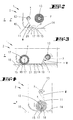
- FIG. 2 shows a cross section through the region of a wiper body W in a first embodiment.
- a supply roll 12 and a second roll 13 are initially provided, the axes of rotation x and y are aligned transversely to the direction of travel r and r '.
- the two axes x and y on a common, parallel to the floor 10 to be cleaned aligned level.
- an opening 15 is provided in the chassis bottom 14. This is slit-shaped with a longitudinal extent transverse to the usual direction of travel r or r '.
- a bottom contact portion 20 is positioned forming. Whose roll axis z extends parallel spatially offset to the axes x and y of the rollers 12 and 13. The arrangement of the roller body 16 is further made such that this enters the opening 15 in the operating position a ground contact position to the bottom 10.
- the wiper belt 11 extends through the opening 15 passing and deflected over the roller body 16 to the second roller 13, on which the wiper belt 11 is wound again.
- the wiper belt 11 is always under tension so that it does not sag between the supply roll 12 and the roll body 16 or between the roll body 16 and the secondary roll 13.
- the roller body 16 forms in connection with the wiper strip 11 which partially surrounds the wiper body W.
- FIG. 2 only a front end region of the device 1 is shown in cross section.
- the wiper body solution proposed there can also be provided additionally or alternatively in the rear region of the device 1.
- the device 1 - as in principle in the other embodiments - on the or the wiper body W are supported on the floor to be cleaned.
- the chassis of the device 1 may have separate rollers over which the device 1 is supported on the floor 10 to be cleaned.
- the wiping bodies W are guided on the floor 10 only with their own weight and / or under a defined spring preload. It is achieved as a decoupling of the user via the handle 6 initiated force and the weight of the device.
- the soil wet cleaning device 1 is equipped with a moistening device, not shown, for the wiper body W. In addition, if necessary, with a suction for Saugbodenbearbeitung.
- a moistening device for the wiper body W.
- a suction for Saugbodenbeailleung is based on the non-prepublished German patent application DE 10 2006 055 674 Reference is hereby made, the content of which is hereby incorporated in full into the disclosure of the present invention, also for the purpose of including features of this patent application in claims of the present invention.
- the roller body 16 can be supported in a co-rotating manner, so that it is entrained by the wiper belt 11 during the unwinding of the wiper belt 11 from the supply roll 12 or during the winding onto the secondary roller 13. It is also conceivable to non-rotatably support the roller body 16, so that the wiper belt 11 slips over the roller body 16 in such a configuration.
- a wiper edge 17 aligned transversely to the direction of travel r or r ' is achieved in the contact region between roller body 16 and floor 10 to be cleaned or between the wiper belt 11 clamped over roller body 16 and floor 10.
- the wiper belt 11 is continuously or gradually transported forward, so for example by the action of a controlled electric motor on the second roller 13.
- the transport speed of the wiper belt 11 is chosen to be much lower than the usual driving speed of the device 1, so that even at a continuous transport of the wiper belt 11, a quasi-static wiping edge 17 sets.
- the transport of the wiper belt 11 can be done depending on the direction of travel or at intervals, so that at certain intervals always new, unused wiping edges 17 get into the operative position.
- roller body 16 may also be a device housing side, projecting into the opening 15 edge of a web provided here serve as a deflection point and forming element for the wiper edge 17.
- FIG. 3 Another alternative shows the illustration in FIG. 3 , Again, a supply roll 12 and a second roller 13 is provided for winding the wiper strip 11 inside the device.
- the wiping edge 17 is given in this embodiment directly in the region of the supply roll 12.
- This supply roll 12 is always in ground contact position, what this is supported in vertically aligned slot guides 18.
- the supply roll 12 dives accordingly partially through the openings 15 of the chassis bottom 4.
- Parallel offset in the embodiment opposite to the direction of travel r is a second likewise slot-shaped opening 19 is provided.
- the underflow Chassis foundedabites forms the ground contact part 20, which is shaped as a flat body 21 accordingly.
- the development or winding of the wiper belt 11 is preferably carried out as described in the first embodiment by a controlled electric motor which acts on the second roller 13.
- FIGS. 4 to 6 show a further embodiment with a supply roll 12 and a second roll 13. Also in this embodiment, which forms on the floor 10 to be cleaned supply roll 12 along the line of contact to the bottom 10, the wiper edge 17th
- the second roller 13 is positioned vertically above the supply roll 12. Accordingly, the axes of rotation x and y of the rollers 12 and 13 are positioned within a plane perpendicular to the chassis bottom 14 level.
- the wiper belt 11 is transported continuously or stepwise, to offer an always new, unused wiper edge 17.
- the wiper belt 11 is wound onto the secondary roller 13 so that the soiled belt surface 22 is wound inwardly facing the secondary roller 13, this in a rotational movement of the second roller 13 as shown in the FIGS. 4 and 5 in the clockwise direction and during rotation of the supply roll 12 in the counterclockwise direction.
- the supply roll 12 of this embodiment is supported in slot guides 18, so that with changing diameter in the course of wiper belt development, the supply roll 12 always in the contact position to be cleaned bottom 10 remains, this forming the wiping edge 17th
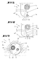
- FIGS. 7 to 9 show two further embodiments in which the supply roll 12 and the secondary roll 13 are received within a hollow body 24 formed as a roller 25.
- the axes x and y of the rollers 12 and 13 extend parallel to the roller axis.
- the hollow body 24 or the roller 25 is provided with a transverse to the direction of travel r or r 'aligned slot-shaped opening 26. Through this opening 26, the wiper tape 11 is guided outwardly from the interior of the hollow body 24 out, after which the wiper tape 11 in the embodiment according to FIG. 7 the outer circumferential surface of the hollow body 24 or the roller 25 is wound around the opening 26 on the secondary roller 13 in a looping manner. Again, the drive is to continuous or incremental Transport of the wiper belt 11 directed to the second roller 13.
- the opening 26 forms a wipe exit and entry.
- the roller 25 rotates about its transverse to the direction of travel r aligned roller axis, this with a winding speed, which gives a relative speed between the self-adjusting wiper edge and the bottom 10 to be cleaned, which is substantially smaller than the usual travel speed of the device 1 in the direction of travel r or r '.
- the rotation of the roller 25 can be continuous or stepwise.
- the roller 25 in one direction of travel may be blocked to form a wiping edge 17, wherein the wiping edge 17 is always readjusted by, for example, incremental advance transport of the wiper belt 11, while in the other direction of travel (for example, direction of travel r ').
- the roller 25 passes freely and also the pre-transport of the wiper belt 11 is interrupted.
- the roller 25 block depending on the direction of travel or rotate freely with the blocking position is defined and the positions as shown in the FIGS. 8 and 9 equivalent. Only in this one rotational position of the roller 25, a wiping edge 17 between the roller body 16 and bottom 10 is offered.
- FIGS. 10 and 11 a solution in which the wiper belt 11 also cooperates with a hollow body 24 formed as a roller 25.
- This roller 25 is provided with evenly distributed over the circumference, slot-like openings 26 which extend transversely to the direction of travel r.
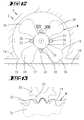
- the wiper belt is guided on the outside over the hollow body 24 and guided in the manner of constrictions in the region of the openings 26 radially inward and there stretched over roller-like deflection body 27. It turns according to the cross-sectional view in FIG. 11 a serpentine path of the wiper belt 11 according to the contour of a cloverleaf. This also increases the total wiping area.
- this roller 25 is also rotatable about a roller axis directed transversely to the direction of travel r, wherein in the illustrated embodiment, the roller 25 has a ratchet-like toothing 28 in the region of an end face, for cooperation with a housing-side spring-loaded locking element 29.
- the roller 25 in a rotational direction over the frictional engagement with the bottom 10 according to the speed of movement of the device 1 freely rotatable. There is no wiping edge 17.
- the wiper belt 11 is arranged in loops which are held by slowly rotating small rollers 30 on the outside of a centrally located rotary transport body 31.
- This inner transport body 31 is provided with external teeth 32 which mesh with counter teeth 33 of the rollers 30 with the interposition of wiper band sections.
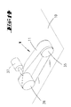
- FIG. 14 shows a wiping body W in another embodiment.
- the wiper strip 11 provided here is in the sense of a Möbius strip with fastened ends turned through 180 ° to one another.
- the wiper belt 11 is guided around two guide rollers 35 and 36, the roller axes are aligned in the direction of travel spaced transversely to the direction of travel. At least one of the rollers 35 and / or 36 is in a ground contact position for forming a wiping edge 17.
- the guide roller 36 is the drive roller, for which purpose it is connected to a schematically illustrated electric motor 37.
- FIGS. 15 and 16 an embodiment in which a wiper belt 11 is guided over two guide rollers 35 and 36.
- the deflecting roller 35 reaching the ground contact position is provided with a dynamic, spiral-shaped wiping edge 38, via which wiping edge 38 the wiper belt 11 is tensioned.
- This deflecting roller 35, which produces the ground contact runs at a relative speed to the wiper belt 11.
- the peripheral speed of the roller is in this case smaller or larger than the translation speed of the wiper belt 11.
- the dynamic wiper edge 38 is expressed through the wiper belt 11 and leads to a transverse to the direction of travel r moving wiper edge region.
- the number of wiping zones is determined by the number of screw threads.
- the described household floor wet cleaning device 1 is designed for sucking and misting wiping hard surfaces of all kinds, so in particular tile floors, laminate or parquet floors, but also stoneware floors.
- the cleaning of inclined surfaces up to vertical surfaces is possible.
- the dampening process may be preceded by a suction, in particular for receiving coarse dirt particles to fine dust.
- the invention which may have meaning both alone and in combination with one of the above-described features, is also a soil wet cleaning device, wherein after a unwinding of the supply roll 12, the supply roll 12 is rewound, upon movement of the supply roll 12 in the same direction as when unwinding ,
- the subject of the invention which may be meaningful both alone and in combination with one of the above-described features, is also a soil wet cleaning apparatus, in which the supply roll 12 is vertically movable with respect to its axis of rotation x.
- the invention which may have meaning both alone and in combination with one of the features described above, is also a soil wet cleaning device in which the wiper belt 11 between the supply roll 12 and the second roll 13 is guided on the bottom side via a ground contact part 20.
- the subject of the invention which may be meaningful both alone and in combination with one of the above-described features, is also a soil wet cleaning appliance in which the soil contact part is a flat body 21.
- the subject matter of the invention which may be meaningful both alone and in combination with one of the above-described features, is also a soil wet cleaning appliance in which the soil contact part (20) is a roll body 16.
- the invention which may have meaning both alone and in combination with one of the above-described features, is also a soil wet cleaning device in which a hollow body 24 is provided with a transversely to the direction of travel r, r 'formed opening 26 and in the opening 26 a Ground contact part 20 is arranged, over which the wiper belt 11 is pulled
- the subject of the invention which may be meaningful both alone and in combination with one of the above-described features, is also a soil wet cleaning apparatus in which the hollow body 24 has a circular cross section.
- the invention which may have meaning both alone and in combination with one of the above-described features, is also a soil wet cleaning device, in which the hollow body 24 about an axis transverse to the direction of travel r, r 'is movable
- the subject matter of the invention which may be meaningful both alone and in combination with one of the above-described features, is also a soil wet cleaning device in which the surface of the rotary transport body (31) is gear-shaped at least in certain areas and in the contact region with a counter-toothing (33). with the interposition of the wiper belt (11) meshes.
- the invention which may have meaning both alone and in combination with one of the above-described features, is also a soil wet cleaning device in which the wiper belt (11) on the outside via a hollow body (24) is guided transversely to the direction of travel (r, r ') extending openings (26) and that in the interior of the hollow body (24) a deflecting body (27) is arranged at a radial distance from the opposite peripheral edge of the opening (26), over which the wiper belt runs, so that in the region of the opening (26) an indentation of the wiper strip (11) results under partial freeing of the deflecting body (27) radially outward.
- the subject of the invention which may be meaningful both alone and in combination with one of the above-described features, is also a soil wet cleaning apparatus, in which a plurality of openings (26) over the circumference of the hollow body (24) are formed.
- the subject matter of the invention which may be meaningful both alone and in combination with one of the above-described features, is also a soil wet cleaning device in which the openings (26) are designed to be circumferentially symmetrical.
- the subject matter of the invention which may be meaningful both alone and in combination with one of the above-described features, is also a soil wet cleaning apparatus in which at least one deflection body (27) is designed as a drive body.
Landscapes
- Cleaning In General (AREA)
- Cleaning Implements For Floors, Carpets, Furniture, Walls, And The Like (AREA)
Applications Claiming Priority (1)
| Application Number | Priority Date | Filing Date | Title |
|---|---|---|---|
| DE200710014506 DE102007014506A1 (de) | 2007-03-27 | 2007-03-27 | Verfahrbares Haushalts-Bodenfeuchtreinigungsgerät |
Publications (1)
| Publication Number | Publication Date |
|---|---|
| EP1974643A2 true EP1974643A2 (fr) | 2008-10-01 |
Family
ID=39511038
Family Applications (1)
| Application Number | Title | Priority Date | Filing Date |
|---|---|---|---|
| EP08101664A Withdrawn EP1974643A2 (fr) | 2007-03-27 | 2008-02-15 | Appareil ménager mobile de nettoyage humide de sol |
Country Status (4)
| Country | Link |
|---|---|
| EP (1) | EP1974643A2 (fr) |
| CN (1) | CN101273863A (fr) |
| DE (1) | DE102007014506A1 (fr) |
| RU (1) | RU2008111682A (fr) |
Families Citing this family (8)
| Publication number | Priority date | Publication date | Assignee | Title |
|---|---|---|---|---|
| US9420932B2 (en) * | 2012-09-17 | 2016-08-23 | Bissell Homecare, Inc. | Steam mop with grout cleaning tool and method |
| CN103190867B (zh) * | 2013-04-15 | 2015-11-11 | 黑龙江工程学院 | 基于莫比乌斯带的擦地机器人 |
| CN106137049B (zh) * | 2015-03-27 | 2019-02-15 | 广州市联特电子科技有限公司 | 一种自移动清洁机器人及其清洁方法 |
| CN110881910A (zh) * | 2019-12-05 | 2020-03-17 | 杨洪新 | 一种家用新型超洁自助清洁机 |
| CN112044823B (zh) * | 2020-09-22 | 2025-01-14 | 上海德欧电气有限公司 | 接触式清洗装置 |
| CN114652224A (zh) * | 2020-12-22 | 2022-06-24 | 广东美的白色家电技术创新中心有限公司 | 清洁基站及清洁系统 |
| CN113317727B (zh) * | 2021-06-29 | 2024-01-26 | 深圳银星智能集团股份有限公司 | 拖擦装置及清洁机器人 |
| US12408806B2 (en) * | 2021-12-22 | 2025-09-09 | AUO Corporation | Cleaning wheel including reels and transmission for cleaning film |
Family Cites Families (1)
| Publication number | Priority date | Publication date | Assignee | Title |
|---|---|---|---|---|
| DE102007054500A1 (de) | 2006-11-23 | 2008-05-29 | Vorwerk & Co. Interholding Gmbh | Verfahrbares Haushalts-Bodenreinigungsgerät sowie Befeuchtungseinrichtung für eine Wischwalze |
-
2007
- 2007-03-27 DE DE200710014506 patent/DE102007014506A1/de not_active Withdrawn
-
2008
- 2008-02-15 EP EP08101664A patent/EP1974643A2/fr not_active Withdrawn
- 2008-03-26 CN CNA2008100884115A patent/CN101273863A/zh active Pending
- 2008-03-26 RU RU2008111682/12A patent/RU2008111682A/ru not_active Application Discontinuation
Also Published As
| Publication number | Publication date |
|---|---|
| RU2008111682A (ru) | 2009-10-10 |
| DE102007014506A1 (de) | 2008-10-02 |
| CN101273863A (zh) | 2008-10-01 |
Similar Documents
| Publication | Publication Date | Title |
|---|---|---|
| EP2063755B1 (fr) | Appareil électro-ménager de nettoyage de sol humide mobile et dispositif d'humidification pour rouleau mouilleur | |
| EP1974643A2 (fr) | Appareil ménager mobile de nettoyage humide de sol | |
| EP3206548B1 (fr) | Machine de nettoyage de surfaces et procédé permettant de faire fonctionner une machine de nettoyage de surfaces | |
| EP2872697B1 (fr) | Balayeuse | |
| DE3147898A1 (de) | Kehrmaschine mit zwei buersten | |
| DE102015103500A1 (de) | Reinigungsgerät | |
| EP4014826B1 (fr) | Appareil de nettoyage du sol | |
| EP0693378A1 (fr) | Appareil pour nettoyer des cylindres | |
| EP0468158A1 (fr) | Appareil d'essorage pour chiffons de nettoyage et similaires | |
| EP2615959B1 (fr) | Système d'entraînement pour un dispositif de nettoyage et dispositiv de nettoyage | |
| EP1974645A1 (fr) | Appareil ménager mobile pour le nettoyage humide de sol | |
| WO2016206941A1 (fr) | Appareil de nettoyage muni d'un rouleau de nettoyage pouvant tourner autour d'un axe de rotation | |
| EP3310235B1 (fr) | Appareil de nettoyage pour une action sur une surface à nettoyer | |
| EP3496585B1 (fr) | Appareil de nettoyage humide avec rouleau de nettoyage | |
| DE102007052982A1 (de) | Reinigungsgerät sowie Reinigungswalze für ein Reinigungsgerät | |
| WO2001076876A1 (fr) | Bobine d"enroulement de chiffon de nettoyage pour des dispositifs de nettoyage | |
| EP1955635B1 (fr) | Appareil d'entretien du sol | |
| EP1838198B1 (fr) | Dispositif de type serpilliere humide a support plat | |
| DE2028093B2 (de) | Bodenkehrmaschine mit mindestens einer drehbaren Walzenbürste | |
| EP1908591A2 (fr) | Dispositif de nettoyage pour une presse rotative | |
| EP4452034B1 (fr) | Machine de nettoyage de surface dotée d'un élément racleur incurvé | |
| EP1094742A1 (fr) | Embout d'aspirateur | |
| DE102016103235A1 (de) | Vorschubeinrichtung für eine reinigungsvorrichtung | |
| WO2024126122A1 (fr) | Appareil de nettoyage de sol équipé d'un réservoir à fluide sale comportant deux zones | |
| DE102008035678A1 (de) | Verfahrbares Haushalts-Bodenfeuchtreinigungsgerät sowie Verfahren zum Betreiben eines solchen Gerätes |
Legal Events
| Date | Code | Title | Description |
|---|---|---|---|
| PUAI | Public reference made under article 153(3) epc to a published international application that has entered the european phase |
Free format text: ORIGINAL CODE: 0009012 |
|
| AK | Designated contracting states |
Kind code of ref document: A2 Designated state(s): AT BE BG CH CY CZ DE DK EE ES FI FR GB GR HR HU IE IS IT LI LT LU LV MC MT NL NO PL PT RO SE SI SK TR |
|
| AX | Request for extension of the european patent |
Extension state: AL BA MK RS |
|
| STAA | Information on the status of an ep patent application or granted ep patent |
Free format text: STATUS: THE APPLICATION IS DEEMED TO BE WITHDRAWN |
|
| 18D | Application deemed to be withdrawn |
Effective date: 20110901 |