EP1974890A1 - Dispositif a encombrement en hauteur réduit de fabrication d'articles moulés par injection - Google Patents
Dispositif a encombrement en hauteur réduit de fabrication d'articles moulés par injection Download PDFInfo
- Publication number
- EP1974890A1 EP1974890A1 EP07425176A EP07425176A EP1974890A1 EP 1974890 A1 EP1974890 A1 EP 1974890A1 EP 07425176 A EP07425176 A EP 07425176A EP 07425176 A EP07425176 A EP 07425176A EP 1974890 A1 EP1974890 A1 EP 1974890A1
- Authority
- EP
- European Patent Office
- Prior art keywords
- oil
- ejection
- hydraulic
- plate
- back plate
- Prior art date
- Legal status (The legal status is an assumption and is not a legal conclusion. Google has not performed a legal analysis and makes no representation as to the accuracy of the status listed.)
- Granted
Links
Images



Classifications
-
- B—PERFORMING OPERATIONS; TRANSPORTING
- B29—WORKING OF PLASTICS; WORKING OF SUBSTANCES IN A PLASTIC STATE IN GENERAL
- B29C—SHAPING OR JOINING OF PLASTICS; SHAPING OF MATERIAL IN A PLASTIC STATE, NOT OTHERWISE PROVIDED FOR; AFTER-TREATMENT OF THE SHAPED PRODUCTS, e.g. REPAIRING
- B29C45/00—Injection moulding, i.e. forcing the required volume of moulding material through a nozzle into a closed mould; Apparatus therefor
- B29C45/17—Component parts, details or accessories; Auxiliary operations
- B29C45/40—Removing or ejecting moulded articles
- B29C45/4005—Ejector constructions; Ejector operating mechanisms
-
- B—PERFORMING OPERATIONS; TRANSPORTING
- B29—WORKING OF PLASTICS; WORKING OF SUBSTANCES IN A PLASTIC STATE IN GENERAL
- B29C—SHAPING OR JOINING OF PLASTICS; SHAPING OF MATERIAL IN A PLASTIC STATE, NOT OTHERWISE PROVIDED FOR; AFTER-TREATMENT OF THE SHAPED PRODUCTS, e.g. REPAIRING
- B29C33/00—Moulds or cores; Details thereof or accessories therefor
- B29C33/76—Cores
-
- B—PERFORMING OPERATIONS; TRANSPORTING
- B29—WORKING OF PLASTICS; WORKING OF SUBSTANCES IN A PLASTIC STATE IN GENERAL
- B29C—SHAPING OR JOINING OF PLASTICS; SHAPING OF MATERIAL IN A PLASTIC STATE, NOT OTHERWISE PROVIDED FOR; AFTER-TREATMENT OF THE SHAPED PRODUCTS, e.g. REPAIRING
- B29C45/00—Injection moulding, i.e. forcing the required volume of moulding material through a nozzle into a closed mould; Apparatus therefor
- B29C45/17—Component parts, details or accessories; Auxiliary operations
- B29C45/40—Removing or ejecting moulded articles
-
- B—PERFORMING OPERATIONS; TRANSPORTING
- B29—WORKING OF PLASTICS; WORKING OF SUBSTANCES IN A PLASTIC STATE IN GENERAL
- B29C—SHAPING OR JOINING OF PLASTICS; SHAPING OF MATERIAL IN A PLASTIC STATE, NOT OTHERWISE PROVIDED FOR; AFTER-TREATMENT OF THE SHAPED PRODUCTS, e.g. REPAIRING
- B29C45/00—Injection moulding, i.e. forcing the required volume of moulding material through a nozzle into a closed mould; Apparatus therefor
- B29C45/17—Component parts, details or accessories; Auxiliary operations
- B29C45/40—Removing or ejecting moulded articles
- B29C45/44—Removing or ejecting moulded articles for undercut articles
- B29C45/4435—Removing or ejecting moulded articles for undercut articles using inclined, tiltable or flexible undercut forming elements driven by the ejector means
-
- B—PERFORMING OPERATIONS; TRANSPORTING
- B29—WORKING OF PLASTICS; WORKING OF SUBSTANCES IN A PLASTIC STATE IN GENERAL
- B29L—INDEXING SCHEME ASSOCIATED WITH SUBCLASS B29C, RELATING TO PARTICULAR ARTICLES
- B29L2031/00—Other particular articles
- B29L2031/30—Vehicles, e.g. ships or aircraft, or body parts thereof
- B29L2031/3044—Bumpers
Definitions
- the present invention relates to the sector of manufacturing plastic parts by means of injection-moulding.
- the present invention relates to an improved apparatus for the injection-moulding of plastic parts.
- the term "part” comprises any object, of any shape and any size, which may be made of plastic by means of an injection-moulding process.
- the term “part” used in the present description and in the claims refers to a vehicle component, for example a bumper fender, a bumper cross-piece, a dashboard or the like.
- plastic or "plastic material” are understood primarily as meaning a material other than metal and in particular is understood as meaning a substantially thermoplastic material with elongation at break values ⁇ 50% (during tensile tests on test pieces at 5 mm/min.) such as polycarbonate, polyester, polybutylene terephthalate, polypropylene, polyamide and derivatives thereof, EPDM-reinforced polypropylene or the like and any combination thereof.
- a plastic material which is particularly suitable for being moulded in order to produce vehicle parts is XENOY ® PC/PBT which is marketed by GE Plastics. This material is already known in the motor car industry and ensures optimum resistance to petrol as well as a high resistance to impacts - also at low temperatures - and durability over time.
- a known apparatus for the injection-moulding of plastic parts comprises two main components: one component called “cavity” and another component called “core”. Moulding of the desired part is performed by joining under pressure the cavity with the core, all of which preceded by injection of liquefied plastic.
- an ejection zone which is situated in the bottom part of the core, between the core and the back plate, is defined.
- An ejection plate and a set of oil-hydraulic pistons are situated in this ejection zone. The set of oil-hydraulic pistons is able to raise the ejection plate in the direction of the cavity or bring it back into the starting position.
- the body of the oil-hydraulic pistons is fixed to the back plate.
- the stem of the oil-hydraulic pistons is fixed, by means of tie-rods, to the ejection plate. Actuation of the oil-hydraulic pistons causes the movement of the ejection plate.
- a known set of oil-hydraulic pistons for an apparatus for the injection-moulding of plastic parts comprises four oil-hydraulic pistons which are arranged in a symmetrical configuration.
- Each oil-hydraulic piston operates in the region of a respective lug projecting from the ejection plate.
- the ejection plate of the known apparatus has a substantially rectangular shape, but projecting parts are formed on the long sides, substantially in the vicinity of the corners.
- Two rigid rods connected together by means of a connecting plate are fixed precisely to each of these projecting parts.
- the top end of the stem of a piston is also fixed to the connecting plate.
- EP 1,588,823 A (Laepple August GmbH & Co.) discloses a device for the manufacture of injection-moulded parts.
- EP 1,407,869 A (Liteco Srl) discloses a standardized modular system for moulds of injection-moulding machines.
- a known apparatus for the injection-moulding of plastic parts with the above-described set of four oil-hydraulic pistons is normally efficient and allows the production of moulded parts with a high degree of precision.
- the gibs are eliminated.
- the core frame is shaped in such a way as to comprise a recess for the ejection plate. This, advantageously, reduces the stroke thus rendering the moulding operation quicker than in the known apparatus. At the same time this solution allows to reduce the dimensions (height) and the weight of the apparatus.
- oil-hydraulic pistons fixed to the back plate and to the ejection plate along the short sides of the latter and in such a way that the oil-hydraulic pistons are situated within the mould.
- only one oil-hydraulic central piston can also be provided.
- the number of oil-hydraulic pistons is reduced from four to two or, in case, also to one.
- an apparatus for the manufacture of injection-moulded plastic parts comprises: a back plate (core side), a core frame fixed to the back plate, an ejection plate and a set of oil-hydraulic ejection pistons for moving the ejection plate with respect to the back plate.
- the core frame is shaped in such a way as to comprise a recess for the ejection plate.
- the core frame is made as one piece and is worked in such a way as to form the above recess.
- the core frame is made as two or more pieces suitably shaped which, when they are joined together, form the above recess.
- the set of oil-hydraulic ejection pistons may consist of a single oil-hydraulic central piston or, alternatively, of a first oil-hydraulic piston and a second oil-hydraulic piston.
- the first and the second oil-hydraulic piston are situated along a middle longitudinal plane of the apparatus.
- the oil-hydraulic pistons may partially be inset in the thickness of the back plate.
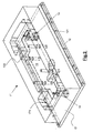
- Figure 1 shows some parts of a known moulding apparatus 1.
- the figure shows a back plate 2, an ejection plate 3, four oil-hydraulic pistons 4 for raising the ejection plate 3 and two sides 5.
- other parts of the apparatus such as the core frame, core and cavity, have not been shown.
- the back plate 2 is flat and has a rectangular shape.
- the four oil-hydraulic pistons 4 and two sides 5 are fixed to it.
- Each side 5 is formed by three parts or gibs.
- the total number of gibs is therefore six.
- Spacers 6, typically with a circular cross-section, are also fixed to the back plate 2.
- the oil-hydraulic pistons 4, the sides 5 and the spacers 6 all extend perpendicularly with respect to the back plate 2 from a same side thereof.
- the ejection plate 3 has a rectangular shape, but has four lugs 31 projecting from its two long sides.
- the ejection plate 3 of the known apparatus 1 has the form of a double cross, where the arms of the double cross consist of the projecting lugs 31.
- each side 5 consists of three parts (52, 53, 54). Each opening 51 along the sides is wide enough for allowing the lugs 31 of the ejection plate 3 to pass through.
- each piston 4 The body 41 of each piston 4 is fixed to the back plate 2 in the vicinity of a respective opening 51.
- the end of the stem 42 of each piston 4 is fixed to a bridge-like connecting element 43.
- each bridge-like connecting element 43 is fixed to a pair of rods 44.
- the other end of the rods 44 is fixed to the ejection plate 3 in the region of the projecting lugs 31.
- the stem 42 moves outwards from the body 41 of the piston and the ejection plate 3 is separated from the back plate 2.
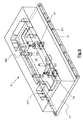
- Figure 2 shows some parts of a moulding apparatus 11 according to a first embodiment of the present invention.
- this figure shows a back plate 12 (core side) with holes 121 for fixing to a press (not shown), an ejection plate 13, two oil-hydraulic pistons 14 for raising the ejection plate 13 and the core frame 17.
- a back plate 12 core side
- ejection plate 13 two oil-hydraulic pistons 14 for raising the ejection plate 13 and the core frame 17.
- other parts of the apparatus 11, such as the core and cavity (which are however visible in Figure 3 ) have not been shown.
- the oil-hydraulic pistons 14 are shown with dotted lines as though they are covered by the core frame and the ejection plate.
- the guides 122 projecting perpendicularly out from the back plate are partially shown with dotted lines as well.
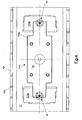
- the shape of the core frame 17 reminds that of a parallelepiped.
- a recess 171 is provided.
- the recess 171 is up to a first depth (this part of the recess 171 is shown with reference number 171 a) along the ends of the core frame 17 and up to a second depth (this part of the recess 171 is shown with reference number 171b) along the middle part.
- the second depth is useful in order to house the ejection plate 13.
- the shape of the two-depth recess is clearly shown in Figure 4 .
- Figure 4 also clearly shows the shape of the ejection plate 13. Such a shape can remind that of a rectangle, in which the sides are narrower than the middle part.
- the two oil-hydraulic pistons 14 At the outer ends of the ejection plate there are the two oil-hydraulic pistons 14.
- Four circular cross-sectioned guides perform the traversing movement of the ejection plate.
- the back plate 12 is substantially flat and has a substantially rectangular shape.
- the two oil-hydraulic pistons 14 and the core frame 17 are fixed thereto.
- the oil-hydraulic pistons 14 able to raise the ejection plate 13 are advantageously positioned, opposite each other, along the shorter sides of the ejection plate 13. Preferably, they are situated in the centre of the short sides of the ejection plate 3. In other words, they are positioned along a longitudinal axis of the apparatus 11 within the mould.
- the two oil-hydraulic pistons 14 are fixed to the back plate in any suitable manner, for example using fixing means of the threaded type or by means of welding. Conveniently, the two oil-hydraulic pistons 14 are fixed to the back plate by means of fixing screws. They may be fixed to the face of the back plate 2 which faces the ejection plate 3 or may be inset (as shown in the cross-section of Figure 3 ) in the thickness of the back plate 12.
- the core frame was positioned above the gibs and therefore the stroke of the ejection plate had to be longer than that performed by the ejection plate of the apparatus according to the present invention, which is inset in the core frame. In other words, the height of the apparatus according to the present invention is reduced than that of the known apparatus.
- the core frame according to the present invention can be made as one piece, as shown in the various figures, or as two or more pieces.
- the recess referred to above is obtained by working a workpiece.
- the recess is obtained by suitably and separately working every single piece and, once they are joined together, they form the core frame 17 according to the invention.
- the whole apparatus 11 according to the first embodiment turns out to be more closed and protected than the known apparatus.
- the two oil-hydraulic pistons 14 are situated within the mould profile.
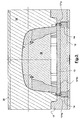
- Figure 3 shows a part of a longitudinal section, in the region of the oil-hydraulic pistons 14, through the apparatus 11 according to the first embodiment of the present invention.
- Figure 3 shows, in relation to the first embodiment, the back plate 12 (core side), the ejection plate 13, the core frame 17, the core 18 and the cavity 19 which define between them the mould cavity.
- the pistons 14 are also shown cross-sectioned.
- Reference number 20 indicates the back plate on the side of the cavity.
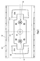
- FIGS 5 , 6 and 7 show a second embodiment of the present invention.
- the same parts have been indicated with the same reference numbers except followed by an apostrophe.
- the only substantial difference between the apparatus 11 according to the first embodiment and the apparatus 11' according to the second embodiment is in the position of the two oil-hydraulic pistons 14'.
- the two oil-hydraulic pistons 14' are no longer positioned along two outer edges of the ejection plate, but are positioned more internally within the said ejection plate 13'.
- two holes are made within which the bodies of the two oil-hydraulic pistons 14' are introduced.
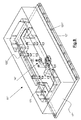
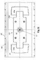
- FIGS 8 , 9 and 10 show a third embodiment of the present invention.
- the apparatus 11" comprises only one oil-hydraulic piston 14" which is positioned substantially in the middle of the mould.
- the ejection plate 13" there is only one central hole within which the body of the oil-hydraulic piston 14" is introduced.
- the size of the single oil-hydraulic piston 14" is such as to be able to exert a pressure equal to that exerted by the two oil-hydraulic pistons 14 and 14".
Landscapes
- Engineering & Computer Science (AREA)
- Mechanical Engineering (AREA)
- Manufacturing & Machinery (AREA)
- Moulds For Moulding Plastics Or The Like (AREA)
- Injection Moulding Of Plastics Or The Like (AREA)
Priority Applications (4)
| Application Number | Priority Date | Filing Date | Title |
|---|---|---|---|
| ES07425176.0T ES2617584T3 (es) | 2007-03-26 | 2007-03-26 | Aparato de altura reducida para la fabricación de piezas de plástico moldeadas por inyección |
| EP07425176.0A EP1974890B1 (fr) | 2007-03-26 | 2007-03-26 | Dispositif a encombrement en hauteur réduit de fabrication d'articles moulés par injection |
| PL07425176T PL1974890T3 (pl) | 2007-03-26 | 2007-03-26 | Urządzenie o zmniejszonej wysokości do wytwarzania formowanych wtryskowo części z tworzywa sztucznego |
| PT74251760T PT1974890T (pt) | 2007-03-26 | 2007-03-26 | Um aparelho de altura reduzida para o fabrico de peças de plástico moldadas por injeção |
Applications Claiming Priority (1)
| Application Number | Priority Date | Filing Date | Title |
|---|---|---|---|
| EP07425176.0A EP1974890B1 (fr) | 2007-03-26 | 2007-03-26 | Dispositif a encombrement en hauteur réduit de fabrication d'articles moulés par injection |
Publications (2)
| Publication Number | Publication Date |
|---|---|
| EP1974890A1 true EP1974890A1 (fr) | 2008-10-01 |
| EP1974890B1 EP1974890B1 (fr) | 2016-12-14 |
Family
ID=38290171
Family Applications (1)
| Application Number | Title | Priority Date | Filing Date |
|---|---|---|---|
| EP07425176.0A Active EP1974890B1 (fr) | 2007-03-26 | 2007-03-26 | Dispositif a encombrement en hauteur réduit de fabrication d'articles moulés par injection |
Country Status (4)
| Country | Link |
|---|---|
| EP (1) | EP1974890B1 (fr) |
| ES (1) | ES2617584T3 (fr) |
| PL (1) | PL1974890T3 (fr) |
| PT (1) | PT1974890T (fr) |
Cited By (1)
| Publication number | Priority date | Publication date | Assignee | Title |
|---|---|---|---|---|
| FR3007316A1 (fr) * | 2013-06-21 | 2014-12-26 | Faurecia Bloc Avant | Dispositif pour la fabrication d'une piece en plastique moulee et moule comprenant un tel dispositif |
Citations (7)
| Publication number | Priority date | Publication date | Assignee | Title |
|---|---|---|---|---|
| JPS60157820A (ja) * | 1984-01-27 | 1985-08-19 | Toyota Motor Corp | 射出成形金型 |
| JPH07266384A (ja) * | 1994-03-28 | 1995-10-17 | Mazda Motor Corp | 射出成形用金型 |
| EP0700766A2 (fr) * | 1994-09-09 | 1996-03-13 | August Läpple GmbH & Co. | Dispositif pour fabriquer des articles moulés par injection |
| JPH08174607A (ja) * | 1994-12-27 | 1996-07-09 | Toyoda Gosei Co Ltd | 射出成形用金型 |
| JPH1024424A (ja) * | 1996-07-09 | 1998-01-27 | Honda Motor Co Ltd | 樹脂成形用金型 |
| DE10048894A1 (de) * | 1999-10-04 | 2001-05-31 | Sumitomo Chemical Co | Formenschliessvorrichtung für Spritzgiessverfahren |
| KR20020095653A (ko) * | 2001-06-15 | 2002-12-28 | 현대자동차주식회사 | 범퍼 금형의 이젝팅 장치 |
Family Cites Families (1)
| Publication number | Priority date | Publication date | Assignee | Title |
|---|---|---|---|---|
| ITMI20051979A1 (it) * | 2005-10-18 | 2007-04-19 | Ilma Plastica S R L | Apparecchiatura di stampaggio di materie plastiche in particolare per lo stampaggio di parti di carrozzeria di veicoli |
-
2007
- 2007-03-26 PT PT74251760T patent/PT1974890T/pt unknown
- 2007-03-26 ES ES07425176.0T patent/ES2617584T3/es active Active
- 2007-03-26 EP EP07425176.0A patent/EP1974890B1/fr active Active
- 2007-03-26 PL PL07425176T patent/PL1974890T3/pl unknown
Patent Citations (7)
| Publication number | Priority date | Publication date | Assignee | Title |
|---|---|---|---|---|
| JPS60157820A (ja) * | 1984-01-27 | 1985-08-19 | Toyota Motor Corp | 射出成形金型 |
| JPH07266384A (ja) * | 1994-03-28 | 1995-10-17 | Mazda Motor Corp | 射出成形用金型 |
| EP0700766A2 (fr) * | 1994-09-09 | 1996-03-13 | August Läpple GmbH & Co. | Dispositif pour fabriquer des articles moulés par injection |
| JPH08174607A (ja) * | 1994-12-27 | 1996-07-09 | Toyoda Gosei Co Ltd | 射出成形用金型 |
| JPH1024424A (ja) * | 1996-07-09 | 1998-01-27 | Honda Motor Co Ltd | 樹脂成形用金型 |
| DE10048894A1 (de) * | 1999-10-04 | 2001-05-31 | Sumitomo Chemical Co | Formenschliessvorrichtung für Spritzgiessverfahren |
| KR20020095653A (ko) * | 2001-06-15 | 2002-12-28 | 현대자동차주식회사 | 범퍼 금형의 이젝팅 장치 |
Cited By (1)
| Publication number | Priority date | Publication date | Assignee | Title |
|---|---|---|---|---|
| FR3007316A1 (fr) * | 2013-06-21 | 2014-12-26 | Faurecia Bloc Avant | Dispositif pour la fabrication d'une piece en plastique moulee et moule comprenant un tel dispositif |
Also Published As
| Publication number | Publication date |
|---|---|
| EP1974890B1 (fr) | 2016-12-14 |
| ES2617584T3 (es) | 2017-06-19 |
| PT1974890T (pt) | 2017-03-10 |
| PL1974890T3 (pl) | 2017-07-31 |
Similar Documents
| Publication | Publication Date | Title |
|---|---|---|
| US20130052296A1 (en) | Injection mold | |
| US20020167115A1 (en) | Injection molding method and injection mold assembly | |
| KR20140037840A (ko) | 언더컷 처리 기구 | |
| WO2019034312A1 (fr) | Moule, procédé de formation d'un composant moulé et procédés de fourniture d'un moule | |
| EP3461612B1 (fr) | Mécanisme de traitement de contre-dépouille et matrice de moulage | |
| EP3326780B1 (fr) | Mécanisme de traitement de contre-dépouille et matrice de moulage | |
| EP1974890B1 (fr) | Dispositif a encombrement en hauteur réduit de fabrication d'articles moulés par injection | |
| EP2454068A1 (fr) | Moule pour le moulage par injection d'éléments avec des contre-dépouilles réalisés en matière plastique, avec un système d'éjection intégré | |
| EP1839838B1 (fr) | Dispositif d'éjection pour une presse à injecter | |
| JP3945207B2 (ja) | 射出成形装置 | |
| KR102130311B1 (ko) | 강판 적층 코어로의 용탕 침투현상을 방지하기 위한 회전자용 고압주조 금형 | |
| CN101119837A (zh) | 用于具有多层模具的注塑机的合模装置 | |
| KR100892391B1 (ko) | 사출기 | |
| CN111050948B (zh) | 铸造装置 | |
| CN105014880A (zh) | 一种厚壁实心注塑产品成型模具 | |
| US20040075195A1 (en) | Ejectorsystem | |
| CN100457415C (zh) | 模具保持器 | |
| CN216885013U (zh) | 行位机构和注塑模具 | |
| CN216760631U (zh) | 整形注塑模具 | |
| CN219427379U (zh) | 模具制品顶出结构 | |
| EP2528722B1 (fr) | Moule pour le moulage par injection de pièces de matière plastique | |
| JP3694695B1 (ja) | 複合連結長尺物の成形金型 | |
| CN217531765U (zh) | 一种模具内再压缩装置 | |
| CN110883230A (zh) | 一种冲压模具 | |
| CN115946308A (zh) | 一种用于注塑模具的双顶出机构及注塑模具 |
Legal Events
| Date | Code | Title | Description |
|---|---|---|---|
| PUAI | Public reference made under article 153(3) epc to a published international application that has entered the european phase |
Free format text: ORIGINAL CODE: 0009012 |
|
| AK | Designated contracting states |
Kind code of ref document: A1 Designated state(s): AT BE BG CH CY CZ DE DK EE ES FI FR GB GR HU IE IS IT LI LT LU LV MC MT NL PL PT RO SE SI SK TR |
|
| AX | Request for extension of the european patent |
Extension state: AL BA HR MK RS |
|
| 17P | Request for examination filed |
Effective date: 20090330 |
|
| AKX | Designation fees paid |
Designated state(s): AT BE BG CH CY CZ DE DK EE ES FI FR GB GR HU IE IS IT LI LT LU LV MC MT NL PL PT RO SE SI SK TR |
|
| 17Q | First examination report despatched |
Effective date: 20151116 |
|
| GRAP | Despatch of communication of intention to grant a patent |
Free format text: ORIGINAL CODE: EPIDOSNIGR1 |
|
| INTG | Intention to grant announced |
Effective date: 20160729 |
|
| GRAS | Grant fee paid |
Free format text: ORIGINAL CODE: EPIDOSNIGR3 |
|
| GRAA | (expected) grant |
Free format text: ORIGINAL CODE: 0009210 |
|
| AK | Designated contracting states |
Kind code of ref document: B1 Designated state(s): AT BE BG CH CY CZ DE DK EE ES FI FR GB GR HU IE IS IT LI LT LU LV MC MT NL PL PT RO SE SI SK TR |
|
| REG | Reference to a national code |
Ref country code: GB Ref legal event code: FG4D |
|
| REG | Reference to a national code |
Ref country code: CH Ref legal event code: EP |
|
| REG | Reference to a national code |
Ref country code: IE Ref legal event code: FG4D |
|
| REG | Reference to a national code |
Ref country code: AT Ref legal event code: REF Ref document number: 853179 Country of ref document: AT Kind code of ref document: T Effective date: 20170115 |
|
| REG | Reference to a national code |
Ref country code: DE Ref legal event code: R096 Ref document number: 602007049126 Country of ref document: DE |
|
| PG25 | Lapsed in a contracting state [announced via postgrant information from national office to epo] |
Ref country code: LV Free format text: LAPSE BECAUSE OF FAILURE TO SUBMIT A TRANSLATION OF THE DESCRIPTION OR TO PAY THE FEE WITHIN THE PRESCRIBED TIME-LIMIT Effective date: 20161214 |
|
| REG | Reference to a national code |
Ref country code: PT Ref legal event code: SC4A Ref document number: 1974890 Country of ref document: PT Date of ref document: 20170310 Kind code of ref document: T Free format text: AVAILABILITY OF NATIONAL TRANSLATION Effective date: 20170302 |
|
| REG | Reference to a national code |
Ref country code: SE Ref legal event code: TRGR |
|
| REG | Reference to a national code |
Ref country code: FR Ref legal event code: PLFP Year of fee payment: 11 |
|
| REG | Reference to a national code |
Ref country code: LT Ref legal event code: MG4D |
|
| REG | Reference to a national code |
Ref country code: NL Ref legal event code: MP Effective date: 20161214 |
|
| PG25 | Lapsed in a contracting state [announced via postgrant information from national office to epo] |
Ref country code: GR Free format text: LAPSE BECAUSE OF FAILURE TO SUBMIT A TRANSLATION OF THE DESCRIPTION OR TO PAY THE FEE WITHIN THE PRESCRIBED TIME-LIMIT Effective date: 20170315 Ref country code: LT Free format text: LAPSE BECAUSE OF FAILURE TO SUBMIT A TRANSLATION OF THE DESCRIPTION OR TO PAY THE FEE WITHIN THE PRESCRIBED TIME-LIMIT Effective date: 20161214 |
|
| REG | Reference to a national code |
Ref country code: AT Ref legal event code: MK05 Ref document number: 853179 Country of ref document: AT Kind code of ref document: T Effective date: 20161214 |
|
| PG25 | Lapsed in a contracting state [announced via postgrant information from national office to epo] |
Ref country code: FI Free format text: LAPSE BECAUSE OF FAILURE TO SUBMIT A TRANSLATION OF THE DESCRIPTION OR TO PAY THE FEE WITHIN THE PRESCRIBED TIME-LIMIT Effective date: 20161214 |
|
| REG | Reference to a national code |
Ref country code: ES Ref legal event code: FG2A Ref document number: 2617584 Country of ref document: ES Kind code of ref document: T3 Effective date: 20170619 |
|
| PG25 | Lapsed in a contracting state [announced via postgrant information from national office to epo] |
Ref country code: NL Free format text: LAPSE BECAUSE OF FAILURE TO SUBMIT A TRANSLATION OF THE DESCRIPTION OR TO PAY THE FEE WITHIN THE PRESCRIBED TIME-LIMIT Effective date: 20161214 |
|
| PG25 | Lapsed in a contracting state [announced via postgrant information from national office to epo] |
Ref country code: IS Free format text: LAPSE BECAUSE OF FAILURE TO SUBMIT A TRANSLATION OF THE DESCRIPTION OR TO PAY THE FEE WITHIN THE PRESCRIBED TIME-LIMIT Effective date: 20170414 Ref country code: EE Free format text: LAPSE BECAUSE OF FAILURE TO SUBMIT A TRANSLATION OF THE DESCRIPTION OR TO PAY THE FEE WITHIN THE PRESCRIBED TIME-LIMIT Effective date: 20161214 Ref country code: SK Free format text: LAPSE BECAUSE OF FAILURE TO SUBMIT A TRANSLATION OF THE DESCRIPTION OR TO PAY THE FEE WITHIN THE PRESCRIBED TIME-LIMIT Effective date: 20161214 Ref country code: RO Free format text: LAPSE BECAUSE OF FAILURE TO SUBMIT A TRANSLATION OF THE DESCRIPTION OR TO PAY THE FEE WITHIN THE PRESCRIBED TIME-LIMIT Effective date: 20161214 |
|
| PG25 | Lapsed in a contracting state [announced via postgrant information from national office to epo] |
Ref country code: BG Free format text: LAPSE BECAUSE OF FAILURE TO SUBMIT A TRANSLATION OF THE DESCRIPTION OR TO PAY THE FEE WITHIN THE PRESCRIBED TIME-LIMIT Effective date: 20170314 Ref country code: AT Free format text: LAPSE BECAUSE OF FAILURE TO SUBMIT A TRANSLATION OF THE DESCRIPTION OR TO PAY THE FEE WITHIN THE PRESCRIBED TIME-LIMIT Effective date: 20161214 |
|
| REG | Reference to a national code |
Ref country code: DE Ref legal event code: R097 Ref document number: 602007049126 Country of ref document: DE |
|
| PLBE | No opposition filed within time limit |
Free format text: ORIGINAL CODE: 0009261 |
|
| STAA | Information on the status of an ep patent application or granted ep patent |
Free format text: STATUS: NO OPPOSITION FILED WITHIN TIME LIMIT |
|
| REG | Reference to a national code |
Ref country code: CH Ref legal event code: PL |
|
| 26N | No opposition filed |
Effective date: 20170915 |
|
| PG25 | Lapsed in a contracting state [announced via postgrant information from national office to epo] |
Ref country code: DK Free format text: LAPSE BECAUSE OF FAILURE TO SUBMIT A TRANSLATION OF THE DESCRIPTION OR TO PAY THE FEE WITHIN THE PRESCRIBED TIME-LIMIT Effective date: 20161214 Ref country code: MC Free format text: LAPSE BECAUSE OF FAILURE TO SUBMIT A TRANSLATION OF THE DESCRIPTION OR TO PAY THE FEE WITHIN THE PRESCRIBED TIME-LIMIT Effective date: 20161214 |
|
| REG | Reference to a national code |
Ref country code: IE Ref legal event code: MM4A |
|
| PG25 | Lapsed in a contracting state [announced via postgrant information from national office to epo] |
Ref country code: LU Free format text: LAPSE BECAUSE OF NON-PAYMENT OF DUE FEES Effective date: 20170326 |
|
| PG25 | Lapsed in a contracting state [announced via postgrant information from national office to epo] |
Ref country code: LI Free format text: LAPSE BECAUSE OF NON-PAYMENT OF DUE FEES Effective date: 20170331 Ref country code: SI Free format text: LAPSE BECAUSE OF FAILURE TO SUBMIT A TRANSLATION OF THE DESCRIPTION OR TO PAY THE FEE WITHIN THE PRESCRIBED TIME-LIMIT Effective date: 20161214 Ref country code: IE Free format text: LAPSE BECAUSE OF NON-PAYMENT OF DUE FEES Effective date: 20170326 Ref country code: CH Free format text: LAPSE BECAUSE OF NON-PAYMENT OF DUE FEES Effective date: 20170331 |
|
| REG | Reference to a national code |
Ref country code: FR Ref legal event code: PLFP Year of fee payment: 12 |
|
| PG25 | Lapsed in a contracting state [announced via postgrant information from national office to epo] |
Ref country code: MT Free format text: LAPSE BECAUSE OF NON-PAYMENT OF DUE FEES Effective date: 20170326 |
|
| PG25 | Lapsed in a contracting state [announced via postgrant information from national office to epo] |
Ref country code: HU Free format text: LAPSE BECAUSE OF FAILURE TO SUBMIT A TRANSLATION OF THE DESCRIPTION OR TO PAY THE FEE WITHIN THE PRESCRIBED TIME-LIMIT; INVALID AB INITIO Effective date: 20070326 |
|
| PG25 | Lapsed in a contracting state [announced via postgrant information from national office to epo] |
Ref country code: CY Free format text: LAPSE BECAUSE OF NON-PAYMENT OF DUE FEES Effective date: 20161214 |
|
| P01 | Opt-out of the competence of the unified patent court (upc) registered |
Effective date: 20230523 |
|
| PGFP | Annual fee paid to national office [announced via postgrant information from national office to epo] |
Ref country code: SE Payment date: 20250321 Year of fee payment: 19 |
|
| PGFP | Annual fee paid to national office [announced via postgrant information from national office to epo] |
Ref country code: PT Payment date: 20250313 Year of fee payment: 19 Ref country code: DE Payment date: 20250319 Year of fee payment: 19 |
|
| PGFP | Annual fee paid to national office [announced via postgrant information from national office to epo] |
Ref country code: BE Payment date: 20250319 Year of fee payment: 19 |
|
| PGFP | Annual fee paid to national office [announced via postgrant information from national office to epo] |
Ref country code: FR Payment date: 20250325 Year of fee payment: 19 Ref country code: PL Payment date: 20250224 Year of fee payment: 19 Ref country code: CZ Payment date: 20250318 Year of fee payment: 19 |
|
| PGFP | Annual fee paid to national office [announced via postgrant information from national office to epo] |
Ref country code: IT Payment date: 20250321 Year of fee payment: 19 Ref country code: GB Payment date: 20250319 Year of fee payment: 19 |
|
| PGFP | Annual fee paid to national office [announced via postgrant information from national office to epo] |
Ref country code: TR Payment date: 20250318 Year of fee payment: 19 |
|
| PGFP | Annual fee paid to national office [announced via postgrant information from national office to epo] |
Ref country code: ES Payment date: 20250425 Year of fee payment: 19 |