EP1975332A2 - Coffrage perdu pour murs en béton armé isolés thermiquement - Google Patents
Coffrage perdu pour murs en béton armé isolés thermiquement Download PDFInfo
- Publication number
- EP1975332A2 EP1975332A2 EP08005287A EP08005287A EP1975332A2 EP 1975332 A2 EP1975332 A2 EP 1975332A2 EP 08005287 A EP08005287 A EP 08005287A EP 08005287 A EP08005287 A EP 08005287A EP 1975332 A2 EP1975332 A2 EP 1975332A2
- Authority
- EP
- European Patent Office
- Prior art keywords
- panel
- casing
- main
- supplementary
- fact
- Prior art date
- Legal status (The legal status is an assumption and is not a legal conclusion. Google has not performed a legal analysis and makes no representation as to the accuracy of the status listed.)
- Withdrawn
Links
- 239000011150 reinforced concrete Substances 0.000 claims abstract description 11
- 125000006850 spacer group Chemical group 0.000 claims abstract description 9
- 239000004793 Polystyrene Substances 0.000 claims description 5
- 239000000463 material Substances 0.000 claims description 5
- 229920002223 polystyrene Polymers 0.000 claims description 5
- 238000000465 moulding Methods 0.000 claims description 3
- 239000000853 adhesive Substances 0.000 claims description 2
- 230000001070 adhesive effect Effects 0.000 claims description 2
- 238000009434 installation Methods 0.000 claims description 2
- 238000009413 insulation Methods 0.000 description 7
- 238000004873 anchoring Methods 0.000 description 4
- 239000004568 cement Substances 0.000 description 4
- 238000004519 manufacturing process Methods 0.000 description 3
- 230000008878 coupling Effects 0.000 description 2
- 238000010168 coupling process Methods 0.000 description 2
- 238000005859 coupling reaction Methods 0.000 description 2
- 230000000295 complement effect Effects 0.000 description 1
- 238000010276 construction Methods 0.000 description 1
- 238000011065 in-situ storage Methods 0.000 description 1
- 238000000034 method Methods 0.000 description 1
- 238000000926 separation method Methods 0.000 description 1
Images

Classifications
-
- E—FIXED CONSTRUCTIONS
- E04—BUILDING
- E04B—GENERAL BUILDING CONSTRUCTIONS; WALLS, e.g. PARTITIONS; ROOFS; FLOORS; CEILINGS; INSULATION OR OTHER PROTECTION OF BUILDINGS
- E04B2/00—Walls, e.g. partitions, for buildings; Wall construction with regard to insulation; Connections specially adapted to walls
- E04B2/84—Walls made by casting, pouring, or tamping in situ
- E04B2/86—Walls made by casting, pouring, or tamping in situ made in permanent forms
- E04B2/8647—Walls made by casting, pouring, or tamping in situ made in permanent forms with ties going through the forms
-
- E—FIXED CONSTRUCTIONS
- E04—BUILDING
- E04B—GENERAL BUILDING CONSTRUCTIONS; WALLS, e.g. PARTITIONS; ROOFS; FLOORS; CEILINGS; INSULATION OR OTHER PROTECTION OF BUILDINGS
- E04B2/00—Walls, e.g. partitions, for buildings; Wall construction with regard to insulation; Connections specially adapted to walls
- E04B2/84—Walls made by casting, pouring, or tamping in situ
- E04B2/86—Walls made by casting, pouring, or tamping in situ made in permanent forms
- E04B2/8635—Walls made by casting, pouring, or tamping in situ made in permanent forms with ties attached to the inner faces of the forms
- E04B2/8641—Walls made by casting, pouring, or tamping in situ made in permanent forms with ties attached to the inner faces of the forms using dovetail-type connections
-
- E—FIXED CONSTRUCTIONS
- E04—BUILDING
- E04B—GENERAL BUILDING CONSTRUCTIONS; WALLS, e.g. PARTITIONS; ROOFS; FLOORS; CEILINGS; INSULATION OR OTHER PROTECTION OF BUILDINGS
- E04B2/00—Walls, e.g. partitions, for buildings; Wall construction with regard to insulation; Connections specially adapted to walls
- E04B2/84—Walls made by casting, pouring, or tamping in situ
- E04B2/86—Walls made by casting, pouring, or tamping in situ made in permanent forms
- E04B2002/8694—Walls made by casting, pouring, or tamping in situ made in permanent forms with hinged spacers allowing the formwork to be collapsed for transport
Definitions
- the present invention refers to a disposable casing for thermally insulated walls in reinforced concrete.
- disposable casings for thermally insulated walls in reinforced concrete comprising two polystyrene panels which face each other and which are limited from the outside by respective lateral surfaces, and at least two casing spacers which are interposed between the two polystyrene panels themselves at a determined distance from each other.
- Casings of the kind which.have been described above may be mutually and speedily connected to each other in order to make up a structure, which is suitable for receiving a jet of cement within its interior, and once the cement has set it is capable of guaranteeing, in a single solution, both the cement's capacity for mechanical resistance, as well as the polystyrene's capacity for thermal insulation.
- the aim of the present invention is to produce a disposable casing for thermally insulated walls in reinforced concrete which, while presenting a base structure of standard dimensions, will also permit the production of different thermal insulation capacities.
- a disposable casing for thermally insulated walls in reinforced concrete will be produced as set out in Claim 1 herein.
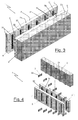
- the number 1 indicates a disposable casing for thermally insulated walls in reinforced concrete in its entirety.
- the casing 1 presents an longer longitudinal axis A, and comprises two main panels 2, which are made of polystyrene, presenting a standard thickness, and which are arranged facing and parallel to each other and to the axis A.
- standard thickness is herein taken to mean the thickness which is commonly adopted for this kind of panelling with, however, the difference that, in the casing 1 which is the subject of the present invention, the two panels 2 might not present the same thickness for reasons which shall be explained in the following description.
- the panels 2 are delimited towards the outside of the casing 1 by respective lateral surfaces 2e, while they are delimited towards the inside of the casing 1 by respective lateral surfaces 2i which define a compartment 6 which is suitable for being filled with cement.
- each panel 2 presents a preferably parallelepiped shape, and is further delimited by an upper surface 2s and by a lower surface 2f, which are parallel to each other and which are transverse to the relative surfaces 2i and 2e.
- the casing 1 comprises two or more casing spacers 3 which in turn each comprise two respective intermediate slats 31, and two anchoring portions 32, which are assembled, preferably but not necessarily, by means of co-moulding with the panels 2, and which are arranged at opposite ends of each pair of slats 31.
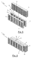
- the anchoring portions 32 face the interior of the compartment 6, and may be rigidly connected to the relative slat 31 in such a way as to form a single body together with the slat 31 itself as is illustrated in FIGURES 1 and 2 , or, as is alternatively illustrated in FIGURES 3 and 4 , may be provided with respective pairs of coupling tracks 33 for rapid coupling with the relative slat 31 as well as to permit the "in situ" assembly of the casing 1, or, as is alternatively illustrated in FIGURES 5 and 6 , may be provided with respective pairs of hinges 34 for relative rotation with the relative slats 31 and to permit the collapse of the casing 1 itself into a transport configuration.
- the casing 1 comprises a supplementary panel 5 which is arranged abutting an external lateral surface 2e of a main panel 2 and a connecting component 7 which is interposed between the supplementary panel 5 and the relative main panel 2 in order to render the supplementary panel 5 and the relative main panel 2 themselves integral in relation to each other.
- the main panel 2 presents a standard thickness as has already been specified above
- the supplementary panel 5 presents, instead, a thickness which may be adapted on the building site to any installation demands and as a means of increasing both the thermal insulation capacity of the casing 1, as well as permitting the production of various thermal insulation capacities.
- the casing 1 may also be provided with two supplementary panels 5 which are arranged abutting the outer surfaces 2e or the relative main panels 2 and such supplementary panel 5 may also have different thicknesses from each other in accordance with the levels of thermal insulation which are to be reached according to necessity.
- the supplementary panel 5 may also be made of the same material as the main panels 2, as it may also be made of other materials which present different thermal insulation capacities.
- the connecting component 7 comprises a number of shaped projections 71 which are integral with the supplementary panel 5 and which are arranged parallel to each other and transverse to the axis A, and, for each shaped projection 71, a respective housing 72 with undercuts which are obtained through the outer surface 2e of the relative main panel.
- the arrangement of the projections 71 and of the housings 72 may be inverted in relation to what has just been described.
- each shaped projection 71 is defined by a respective dovetailed moulding which extends for an entire height of the supplementary panel 5, while the relative housing 72 extends from a surface 2s to a surface 2f and presents a shape which is complementary to the relative projection 71 and is such as to permit the connection of the panel 15 to the panel 2 by means of reciprocal sliding without any successive consequent possibility whatsoever of detachment, or of any separation in a transverse direction of the surface 2e.
- the supplementary panels 6 which have been described above present the advantage of being able to calibrate the thermal insulation capacity of the casing 1 directly on site and in accordance with local weather and climate conditions without the need to vary the thickness of the main panels 2 with obvious positive consequences on the production costs of these products, as well as on the standardisation of the latter.
- the relative panel 2 will present a thickness which is greater than the other panel 2 in that it is able to contain the housings 72, while, whenever the casing 1 is provided with two supplementary panels 5, both the panels 2 can present the same thickness.
- FIGURES 3 and 4 like FIGURES 5 and 6 , illustrate different connection methods between the two panels 2 of the casing 1, which, in the shape of its basic embodiment, provides for the use of spacers 3 which are produced in a single piece, while in the alternative form of embodiment which is shown in FIGURES 3 and 4 it provides for the use of spacers which are detachable transverse to the axis A from the respective anchoring portions by means of the relative tracks 33 permitting the supply of the casing 1 in an unassembled configuration, and in the alternative form of embodiment which is shown in FIGURES 5 and 6 it provides for the use of spacers 3 in which, between the slats 31 and the anchoring portions 32, hinges 33' are arranged to permit the supply of the casing 1 in a collapsed condition with the panels 2 arranged one abutting the other.
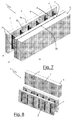
- FIGURES 7 and 8 illustrate a casing 1' which is substantially similar to the casing 1, from which the casing 1' differs due to the fact that the connecting component 7 is defined by a layer 7' of adhesive material which is interposed between the main panel 2 and the relative supplementary panel 6 in such a way as to stick the latter to the former in order to render them integral in relation to each other.
- the layer 7' may be used exclusively for the connection of a supplementary panel 5 to the relative secondary main panel 2, or, according to need, may also be used together with the projections 71 which have been described above.
Landscapes
- Engineering & Computer Science (AREA)
- Architecture (AREA)
- Physics & Mathematics (AREA)
- Electromagnetism (AREA)
- Civil Engineering (AREA)
- Structural Engineering (AREA)
- Building Environments (AREA)
Applications Claiming Priority (1)
| Application Number | Priority Date | Filing Date | Title |
|---|---|---|---|
| IT000214A ITTO20070214A1 (it) | 2007-03-26 | 2007-03-26 | Cassero a perdere per murature termicamente isolate in cemento armato. |
Publications (1)
| Publication Number | Publication Date |
|---|---|
| EP1975332A2 true EP1975332A2 (fr) | 2008-10-01 |
Family
ID=39541539
Family Applications (1)
| Application Number | Title | Priority Date | Filing Date |
|---|---|---|---|
| EP08005287A Withdrawn EP1975332A2 (fr) | 2007-03-26 | 2008-03-20 | Coffrage perdu pour murs en béton armé isolés thermiquement |
Country Status (4)
| Country | Link |
|---|---|
| US (1) | US20080236084A1 (fr) |
| EP (1) | EP1975332A2 (fr) |
| CA (1) | CA2627451A1 (fr) |
| IT (1) | ITTO20070214A1 (fr) |
Cited By (3)
| Publication number | Priority date | Publication date | Assignee | Title |
|---|---|---|---|---|
| EP2843146A1 (fr) * | 2013-08-29 | 2015-03-04 | Loimaan Kivi Oy | Élément de bloc pour mur |
| CN112459346A (zh) * | 2020-12-14 | 2021-03-09 | 赵红玲 | 一种半预制免支模保温混凝土墙体结构及施工工艺 |
| NO20220939A1 (no) * | 2022-08-31 | 2024-03-01 | Dingstad Bjoern Erling | Bygningselement |
Families Citing this family (9)
| Publication number | Priority date | Publication date | Assignee | Title |
|---|---|---|---|---|
| EP2118393A4 (fr) * | 2007-02-02 | 2015-11-04 | Matériaux De Construction Oldcastle Canada Inc | Mur avec parement décoratif |
| US9206599B2 (en) | 2007-02-02 | 2015-12-08 | Les Materiaux De Construction Oldcastle Canada, Inc. | Wall with decorative facing |
| US9670640B2 (en) * | 2010-09-28 | 2017-06-06 | Les Materiaux De Construction Oldcastle Canada, Inc. | Retaining wall |
| US9441342B2 (en) * | 2010-09-28 | 2016-09-13 | Les Materiaux De Construction Oldcastle Canada, In | Retaining wall |
| MX380348B (es) * | 2010-09-28 | 2025-03-12 | Les Materiaux De Construction Oldcastle Canada Inc | Muro de contencion. |
| PL2959065T3 (pl) | 2013-02-25 | 2024-04-08 | Les Matériaux De Construction Oldcastle Canada, Inc. | Zestaw ścianowy |
| US9453341B1 (en) * | 2015-08-18 | 2016-09-27 | Hengestone Holdings, Inc. | Wall system having core supporting blocks and decorative fascia blocks |
| SG11201901481UA (en) * | 2016-09-01 | 2019-03-28 | Rise Form Pty Ltd | Improvements in formwork |
| US11352787B2 (en) * | 2019-06-18 | 2022-06-07 | Victor Amend | Concrete form panel, and concrete formwork comprising same |
Family Cites Families (23)
| Publication number | Priority date | Publication date | Assignee | Title |
|---|---|---|---|---|
| GB1169723A (en) * | 1966-03-22 | 1969-11-05 | Roher Bohm Ltd | Form for Cementitious Material |
| FR2552472B2 (fr) * | 1983-02-08 | 1985-11-08 | Ott Renaud | Systeme constructif utilisant des coffrages perdus notamment isolants et armes |
| CH645152A5 (de) * | 1982-04-23 | 1984-09-14 | Aregger Bau Ag | Schalungselement fuer die mantelbetonbauweise. |
| US4478021A (en) * | 1982-09-30 | 1984-10-23 | Person Gary J | Construction material, a modular, pre-insulated and furred structural masonry building block |
| US4696138A (en) * | 1984-02-06 | 1987-09-29 | Bullock Christopher A | Insulation configurations and method of increasing insulation efficiency |
| US4574550A (en) * | 1984-05-21 | 1986-03-11 | Jack Maschhoff | Building wall and insulation assembly |
| US5351454A (en) * | 1990-01-22 | 1994-10-04 | Hoechst Aktiengesellschaft | Self-supporting facade component in sandwich construction |
| US5845449A (en) * | 1994-11-04 | 1998-12-08 | I.S.M., Inc. | Concrete forming system with brace ties |
| DE29601827U1 (de) * | 1996-02-03 | 1996-03-14 | Gebhart, Siegfried, 88317 Aichstetten | Stein, insbesondere Schalungs- oder Blockstein |
| US6151856A (en) * | 1996-04-04 | 2000-11-28 | Shimonohara; Takeshige | Panels for construction and a method of jointing the same |
| US5896714A (en) * | 1997-03-11 | 1999-04-27 | Cymbala; Patrick M. | Insulating concrete form system |
| US6148576A (en) * | 1998-08-19 | 2000-11-21 | Janopaul, Jr.; Peter | Energy conserving wall unit and method of forming same |
| CA2704828C (fr) * | 1999-03-30 | 2012-09-25 | Arxx Building Products Inc. | Element en pont pour parois de coffre de beton |
| US6318040B1 (en) * | 1999-10-25 | 2001-11-20 | James D. Moore, Jr. | Concrete form system and method |
| US6240692B1 (en) * | 2000-05-26 | 2001-06-05 | Louis L. Yost | Concrete form assembly |
| CN1210472C (zh) * | 2000-12-08 | 2005-07-13 | 矢内始 | 混凝土建筑物用的模板砌块及其制造装置和建造方法以及利用其建造的混凝土建筑物 |
| US6851239B1 (en) * | 2002-11-20 | 2005-02-08 | Hohmann & Barnard, Inc. | True-joint anchoring systems for cavity walls |
| US20040177579A1 (en) * | 2003-03-10 | 2004-09-16 | Innovative Construction Technologies, Inc. | Reinforced foam articles |
| WO2006021222A1 (fr) * | 2004-03-16 | 2006-03-02 | MÖBUS, Daniela | Element paroi |
| CZ20032141A3 (cs) * | 2003-08-06 | 2005-05-18 | Canstroy Cz, S. R. O. | Systém izolačního bednění pro betonovou stěnu a kloubově uložené rozpěrné spojovací žebro |
| HRP20040578B1 (hr) * | 2004-06-21 | 2012-11-30 | Pjer-Miše Veličković | Varijabilne spone za povezivanje oplate od izo-ploäśa visoke nosivosti, ispune i izo-ispune visoke nosivosti za postavljanje a/b ploäśe |
| US20060101756A1 (en) * | 2004-10-29 | 2006-05-18 | Mcclure Larry M | Insulated masonry block and method for producing same |
| US7827752B2 (en) * | 2006-01-11 | 2010-11-09 | Aps Holdings, Llc | Insulating concrete form having locking mechanism engaging tie with anchor |
-
2007
- 2007-03-26 IT IT000214A patent/ITTO20070214A1/it unknown
-
2008
- 2008-03-20 EP EP08005287A patent/EP1975332A2/fr not_active Withdrawn
- 2008-03-24 US US12/053,945 patent/US20080236084A1/en not_active Abandoned
- 2008-03-25 CA CA002627451A patent/CA2627451A1/fr not_active Abandoned
Cited By (3)
| Publication number | Priority date | Publication date | Assignee | Title |
|---|---|---|---|---|
| EP2843146A1 (fr) * | 2013-08-29 | 2015-03-04 | Loimaan Kivi Oy | Élément de bloc pour mur |
| CN112459346A (zh) * | 2020-12-14 | 2021-03-09 | 赵红玲 | 一种半预制免支模保温混凝土墙体结构及施工工艺 |
| NO20220939A1 (no) * | 2022-08-31 | 2024-03-01 | Dingstad Bjoern Erling | Bygningselement |
Also Published As
| Publication number | Publication date |
|---|---|
| CA2627451A1 (fr) | 2008-09-26 |
| US20080236084A1 (en) | 2008-10-02 |
| ITTO20070214A1 (it) | 2008-09-27 |
Similar Documents
| Publication | Publication Date | Title |
|---|---|---|
| EP1975332A2 (fr) | Coffrage perdu pour murs en béton armé isolés thermiquement | |
| CA2633995C (fr) | Composant structurel en bois pour la construction de murs de batiments | |
| DK2653625T3 (en) | Thermally insulating structural element | |
| US9175705B1 (en) | Concrete panel connector | |
| US9540800B2 (en) | Set of profile sections for the construction of walls, panels and angle sections in thermoplastic | |
| US20110209429A1 (en) | Customized modular panel | |
| US9194125B1 (en) | Construction component having embedded internal support structures to provide enhanced structural reinforcement and improved ease of construction therewith | |
| US20160340899A1 (en) | Adjustably Interconnectable Formwork | |
| RU2683446C2 (ru) | Стеновой блок для стеновой конструкции | |
| KR101861016B1 (ko) | 건축용 기능성 마감패널 | |
| US20130125490A1 (en) | Apparatus and method for construction of structures utilizing insulated concrete forms | |
| CA2574694C (fr) | Dispositif de raccordement double | |
| KR101663035B1 (ko) | 큐브형태의 블럭을 이용한 자가 조립형 주택 및 이의 시공방법 | |
| KR100730028B1 (ko) | 조립식 탱크용 단위 패널 | |
| KR101026077B1 (ko) | 큐브구조 건축물용 조립 부재 | |
| EP2096221A3 (fr) | Bloc de construction à isolation intégrée | |
| KR20160060392A (ko) | 벽체 시공용 블록 및 이를 이용한 건축용 벽체 | |
| EP3872273B1 (fr) | Isolateur sismique de coin pour l'adéquation sismique de bâtiments | |
| KR101925956B1 (ko) | 벽체 시공용 블록 및 중공형 판재 기둥을 이용한 코너 연결구조 | |
| PT93940A (pt) | Painel pre-fabricado | |
| RU2237787C1 (ru) | Строительный блок | |
| RU2588589C1 (ru) | Пустотелая стена | |
| KR20140059333A (ko) | 벽체 패널유닛과 이를 이용한 벽체 구조체 | |
| RU2587659C2 (ru) | Система модульной внутренней стены | |
| EP2546426A2 (fr) | Panneau préfabriqué pour construction de murs et mur fait de tel panneaux |
Legal Events
| Date | Code | Title | Description |
|---|---|---|---|
| PUAI | Public reference made under article 153(3) epc to a published international application that has entered the european phase |
Free format text: ORIGINAL CODE: 0009012 |
|
| AK | Designated contracting states |
Kind code of ref document: A2 Designated state(s): AT BE BG CH CY CZ DE DK EE ES FI FR GB GR HR HU IE IS IT LI LT LU LV MC MT NL NO PL PT RO SE SI SK TR |
|
| AX | Request for extension of the european patent |
Extension state: AL BA MK RS |
|
| STAA | Information on the status of an ep patent application or granted ep patent |
Free format text: STATUS: THE APPLICATION IS DEEMED TO BE WITHDRAWN |
|
| 18D | Application deemed to be withdrawn |
Effective date: 20111005 |