EP1975426B1 - Joint rotatif - Google Patents
Joint rotatif Download PDFInfo
- Publication number
- EP1975426B1 EP1975426B1 EP08012885.3A EP08012885A EP1975426B1 EP 1975426 B1 EP1975426 B1 EP 1975426B1 EP 08012885 A EP08012885 A EP 08012885A EP 1975426 B1 EP1975426 B1 EP 1975426B1
- Authority
- EP
- European Patent Office
- Prior art keywords
- running track
- revolving joint
- joint according
- rolling bodies
- torque motor
- Prior art date
- Legal status (The legal status is an assumption and is not a legal conclusion. Google has not performed a legal analysis and makes no representation as to the accuracy of the status listed.)
- Expired - Lifetime
Links
Images

Classifications
-
- F—MECHANICAL ENGINEERING; LIGHTING; HEATING; WEAPONS; BLASTING
- F16—ENGINEERING ELEMENTS AND UNITS; GENERAL MEASURES FOR PRODUCING AND MAINTAINING EFFECTIVE FUNCTIONING OF MACHINES OR INSTALLATIONS; THERMAL INSULATION IN GENERAL
- F16C—SHAFTS; FLEXIBLE SHAFTS; ELEMENTS OR CRANKSHAFT MECHANISMS; ROTARY BODIES OTHER THAN GEARING ELEMENTS; BEARINGS
- F16C19/00—Bearings with rolling contact, for exclusively rotary movement
- F16C19/02—Bearings with rolling contact, for exclusively rotary movement with bearing balls essentially of the same size in one or more circular rows
- F16C19/14—Bearings with rolling contact, for exclusively rotary movement with bearing balls essentially of the same size in one or more circular rows for both radial and axial load
- F16C19/16—Bearings with rolling contact, for exclusively rotary movement with bearing balls essentially of the same size in one or more circular rows for both radial and axial load with a single row of balls
- F16C19/163—Bearings with rolling contact, for exclusively rotary movement with bearing balls essentially of the same size in one or more circular rows for both radial and axial load with a single row of balls with angular contact
- F16C19/166—Four-point-contact ball bearings
-
- F—MECHANICAL ENGINEERING; LIGHTING; HEATING; WEAPONS; BLASTING
- F16—ENGINEERING ELEMENTS AND UNITS; GENERAL MEASURES FOR PRODUCING AND MAINTAINING EFFECTIVE FUNCTIONING OF MACHINES OR INSTALLATIONS; THERMAL INSULATION IN GENERAL
- F16C—SHAFTS; FLEXIBLE SHAFTS; ELEMENTS OR CRANKSHAFT MECHANISMS; ROTARY BODIES OTHER THAN GEARING ELEMENTS; BEARINGS
- F16C19/00—Bearings with rolling contact, for exclusively rotary movement
- F16C19/52—Bearings with rolling contact, for exclusively rotary movement with devices affected by abnormal or undesired conditions
- F16C19/527—Bearings with rolling contact, for exclusively rotary movement with devices affected by abnormal or undesired conditions related to vibration and noise
-
- F—MECHANICAL ENGINEERING; LIGHTING; HEATING; WEAPONS; BLASTING
- F16—ENGINEERING ELEMENTS AND UNITS; GENERAL MEASURES FOR PRODUCING AND MAINTAINING EFFECTIVE FUNCTIONING OF MACHINES OR INSTALLATIONS; THERMAL INSULATION IN GENERAL
- F16C—SHAFTS; FLEXIBLE SHAFTS; ELEMENTS OR CRANKSHAFT MECHANISMS; ROTARY BODIES OTHER THAN GEARING ELEMENTS; BEARINGS
- F16C27/00—Elastic or yielding bearings or bearing supports, for exclusively rotary movement
- F16C27/06—Elastic or yielding bearings or bearing supports, for exclusively rotary movement by means of parts of rubber or like materials
- F16C27/066—Ball or roller bearings
-
- F—MECHANICAL ENGINEERING; LIGHTING; HEATING; WEAPONS; BLASTING
- F16—ENGINEERING ELEMENTS AND UNITS; GENERAL MEASURES FOR PRODUCING AND MAINTAINING EFFECTIVE FUNCTIONING OF MACHINES OR INSTALLATIONS; THERMAL INSULATION IN GENERAL
- F16C—SHAFTS; FLEXIBLE SHAFTS; ELEMENTS OR CRANKSHAFT MECHANISMS; ROTARY BODIES OTHER THAN GEARING ELEMENTS; BEARINGS
- F16C2240/00—Specified values or numerical ranges of parameters; Relations between them
- F16C2240/40—Linear dimensions, e.g. length, radius, thickness, gap
- F16C2240/54—Surface roughness
-
- F—MECHANICAL ENGINEERING; LIGHTING; HEATING; WEAPONS; BLASTING
- F16—ENGINEERING ELEMENTS AND UNITS; GENERAL MEASURES FOR PRODUCING AND MAINTAINING EFFECTIVE FUNCTIONING OF MACHINES OR INSTALLATIONS; THERMAL INSULATION IN GENERAL
- F16C—SHAFTS; FLEXIBLE SHAFTS; ELEMENTS OR CRANKSHAFT MECHANISMS; ROTARY BODIES OTHER THAN GEARING ELEMENTS; BEARINGS
- F16C2240/00—Specified values or numerical ranges of parameters; Relations between them
- F16C2240/40—Linear dimensions, e.g. length, radius, thickness, gap
- F16C2240/70—Diameters; Radii
-
- F—MECHANICAL ENGINEERING; LIGHTING; HEATING; WEAPONS; BLASTING
- F16—ENGINEERING ELEMENTS AND UNITS; GENERAL MEASURES FOR PRODUCING AND MAINTAINING EFFECTIVE FUNCTIONING OF MACHINES OR INSTALLATIONS; THERMAL INSULATION IN GENERAL
- F16C—SHAFTS; FLEXIBLE SHAFTS; ELEMENTS OR CRANKSHAFT MECHANISMS; ROTARY BODIES OTHER THAN GEARING ELEMENTS; BEARINGS
- F16C2240/00—Specified values or numerical ranges of parameters; Relations between them
- F16C2240/40—Linear dimensions, e.g. length, radius, thickness, gap
- F16C2240/70—Diameters; Radii
- F16C2240/80—Pitch circle diameters [PCD]
-
- F—MECHANICAL ENGINEERING; LIGHTING; HEATING; WEAPONS; BLASTING
- F16—ENGINEERING ELEMENTS AND UNITS; GENERAL MEASURES FOR PRODUCING AND MAINTAINING EFFECTIVE FUNCTIONING OF MACHINES OR INSTALLATIONS; THERMAL INSULATION IN GENERAL
- F16C—SHAFTS; FLEXIBLE SHAFTS; ELEMENTS OR CRANKSHAFT MECHANISMS; ROTARY BODIES OTHER THAN GEARING ELEMENTS; BEARINGS
- F16C2300/00—Application independent of particular apparatuses
- F16C2300/10—Application independent of particular apparatuses related to size
- F16C2300/14—Large applications, e.g. bearings having an inner diameter exceeding 500 mm
-
- F—MECHANICAL ENGINEERING; LIGHTING; HEATING; WEAPONS; BLASTING
- F16—ENGINEERING ELEMENTS AND UNITS; GENERAL MEASURES FOR PRODUCING AND MAINTAINING EFFECTIVE FUNCTIONING OF MACHINES OR INSTALLATIONS; THERMAL INSULATION IN GENERAL
- F16C—SHAFTS; FLEXIBLE SHAFTS; ELEMENTS OR CRANKSHAFT MECHANISMS; ROTARY BODIES OTHER THAN GEARING ELEMENTS; BEARINGS
- F16C2316/00—Apparatus in health or amusement
- F16C2316/10—Apparatus in health or amusement in medical appliances, e.g. in diagnosis, dentistry, instruments, prostheses, medical imaging appliances
Definitions
- Rotary connection with at least one rolling bearing and with an electromotive drive unit wherein the rolling bearing is provided with at least one arranged around the axis of rotation of the rolling bearing rolling elements in contact with at least one drivable by the drive unit raceway.
- a rotary joint is in DE 10210071 A1 described.
- Integrated and low-noise rotary joint systems can be used in a variety of applications and are generally used for drive, connection and support and for position detection of the rotating masses and their connection to static components.
- roller bearing slewing rings are used in computer tomographs. Furthermore, you will find the rolling bearing slewing in similar radiographic equipment for the examination of luggage in the security area z. At airports. With the steady increase in the speeds of these applications with simultaneous demand for reduced noise, low starting torque, small installation space, low weight and high running accuracy known roller bearing slewing compounds are unsuitable and no longer meet the requirements of this application.
- the object is to provide a rotary joint, which meets the aforementioned requirements.
- a measurable running noise on the electric motor driven rotary joint which measured as airborne sound, sum sound pressure level with values of at most 70 dB (A), preferably 67 dB (A).
- the noise measurement is made in 1m horizontal distance from the bearing plane on the theoretically continued line of the rotation axis.
- the rolling bearing has at least an inner raceway and an outer raceway. Also conceivable are several of the raceways in the rolling bearing.
- the rolling elements are in contact, during operation of the rolling bearing in the rolling contact, with at least one inner race and an outer race, alternatively with axially aligned raceways.
- a trained according to invention silent connection system of rolling bearing and drive unit is compact and takes up little space. It safely absorbs high radial, axial and moment loads.
- the direct drive is preferably an integral part of the rotary connection system and therefore requires no additional space.
- the rotating rotary connection system causes in all speed ranges but especially at speeds from 100 rev / min (1 / min), preferably from 160 rev / min by integrating a particularly quiet executed rolling bearing, optionally combined with the structure-borne noise, a particularly low noise level.
- the rotary joint is inexpensive to manufacture due to the small number of components used and its compactness.
- the direct drive ensures that the drive forces of the direct drive without the interposition of other drive components (such as belts or gears, etc.), brake generator deflecting and tensioning rollers are transmitted to the rolling bearing slewing ring.
- the electromotive drive unit which is preferably integrated as a direct drive into the rotary connection, is designed as a torque motor in ring or segmental design, wherein a static component of the rotary connection is connected to at least one stator consisting of iron cores and electrical windings.
- a static component of the rotary connection is connected to at least one stator consisting of iron cores and electrical windings.
- One of the rotating components of the rotary joint is equipped with permanent magnets.
- a torque motor In contrast to the ring motor, a torque motor must be operated in a segmented manner in order to synchronize the magnetic forces of each individual segment, thus achieving the best possible efficiency and the lowest noise level.
- the required input signal of the frequency converter for controlling the segments is provided according to an embodiment of the invention by the integrated sensors for position detection. If very high torques are required (eg with a short start-up phase of the rotating components), efficient operation of the ring motor is also possible due to the controlled operation. Due to the controlled operation of the drive unit high torques at the same time lower power level of the frequency converter can be realized.
- the sensor system has at least one sensor and a signal generator.
- the sensor is used to detect signals from the signal generator (coding) or several of the aforementioned components of any design.
- the coding is formed by an e-lastomergürtel, with alternating polarized magnetized particles (alternately north and south pole) is offset.
- the sensor system can also have other electronic components, for example converters.
- the rolling bearings are single-row or multi-row.
- the rolling elements are balls or rollers that can be held in cages.
- the material of the rolling elements and the raceways is preferably steel or any other conceivable materials, such as the materials with a density that is less than 5 grams per cubic millimeter. Such materials are, for example, ceramic materials.
- the ratio of diameter pitch circle to the diameter of each of the rolling elements of a row is greater than 30: 1, preferably 40: 1, the pitch circle being the imaginary circle concentric with the axis of rotation and irrelevant possible changes in position of the rolling elements due to games in the rolling bearing which is parallel to the axis of rotation aligned center axes of the rolling elements
- the center axes are in roles the axes of rotation and symmetry and imaginary spheres, through the spherical center and parallel to the axis of rotation of the rotary joint extending axes.
- the thin-ring four-point ball bearing is the simplest and most robust bearing design. It is designed so that mean axial, radial and moment loads can be safely absorbed.
- the thin ring bearing with its low intrinsic and dimensional stability is supported by the installation in the surrounding parts.
- wire web bearings angular contact ball bearings and roller bearings are used.
- a conversion part is for example a housing, in which the rolling bearing, or at least one of the bearing rings or at least one of the raceways is integrated and / or a rotor or a shaft on the / the rolling bearing, or at least one of the bearing rings or at least one of the raceways is arranged.
- FIG. 1 shows a rotary joint 1 with at least one rolling bearing 2 and with an electric motor drive unit 3 in a partial section along the axis of rotation 2a and not shown to scale.
- the rolling bearing 2 has a row of rolling elements 4 arranged around the axis of rotation 2 a of the rolling bearing 2.
- the rolling elements 4 are in contact with a drivable by the drive unit raceway 5 on an inner ring 6 and in contact with a raceway 7 on an outer ring 8.
- the outer ring 8 is fixed in a rotationally fixed part in the form of a housing 9.
- a structure-borne sound insulation 10 in the form of a vulcanized on the outer ring 8 insulating layer 11 made of an elastomer.
- the insulating layer 11 is alternatively an insert.
- a rotary motor of the drive unit 3 has permanent magnets 12 which sit directly on a rotor 13 of the rotary joint 1.
- the rotor 13 of the rotary motor is rotatably coupled to the driven track 5 and separated by an orbiting around the axis of rotation 2a air gap 14 of non-illustrated electrical windings of a stator 15 of the rotary motor.
- the ratio of diameter D pitch circle to the diameter K of each of the rolling elements 4 of the series is greater than 30: 1, wherein the pitch circle is the imaginary circle, which is arranged concentrically to the axis of rotation 2a and the aligned parallel to the axis of rotation 2a and in perpendicular in the presentation plane abutting center axes 16 of the rolling elements 4 cuts.
- the rolling elements 4 and bearing rings 6 and 8 are optionally made of steel or ceramic, with combinations of rolling elements or components of the rolling bearing made of steel with components or rolling elements made of ceramic are conceivable.
- a sensor 18 of a sensor 17 and a coding 20 with the at least relative positions in the circumferential direction between the rotor 13 to the stator 15 can be detected.
- the sensor 17 is fixed to the stator 15, the coding 20 on the rotor 13.
- From the sensor goes from a connecting cable 21, which can also be optionally connected to the control unit 22 indicated by dashed lines.
- a connecting cable 19 leads to the drive unit 3, so that the control unit 22 can convert output signals of the sensor 18 into input signals for controlling the rotary motor.
Landscapes
- Engineering & Computer Science (AREA)
- General Engineering & Computer Science (AREA)
- Mechanical Engineering (AREA)
- Rolling Contact Bearings (AREA)
- Motor Or Generator Frames (AREA)
- Support Of The Bearing (AREA)
- Vibration Prevention Devices (AREA)
Claims (15)
- Joint rotatif (1) comprenant au moins un palier à roulement (2) et une unité d'entraînement à moteur électrique (3), le palier à roulement (2) présentant au moins une rangée de corps de roulement (4) disposés autour de l'axe de rotation (2a), et les corps de roulement (4) étant en contact avec au moins un chemin de roulement (5) pouvant être entraîné par l'unité d'entraînement (3), avec des aimants permanents (12) d'un moteur rotatif de l'unité d'entraînement (3) qui sont accouplés de manière solidaire en rotation au chemin de roulement entraîné (5) pour former un rotor (13) du moteur rotatif et qui sont en regard d'un stator (15) du moteur rotatif au niveau d'un entrefer (14) entourant l'axe de rotation (2a), au moins le stator (15) et les aimants permanents (12) étant séparés les uns des autres par l'entrefer (14), caractérisé par des rugosités de surface de la surface du premier chemin de roulement (5) entraîné par l'unité d'entraînement (3) et par des rugosités de surface de la surface d'au moins un deuxième chemin de roulement (7) avec des valeurs Ra < 0,25, la rangée de corps de roulement (4) étant en contact avec le deuxième chemin de roulement (7), et en ce que le rapport du diamètre du cercle partiel au diamètre de chaque corps de roulement individuel d'une rangée est supérieur à 30:1, le cercle partiel étant le cercle imaginaire qui est disposé concentriquement à l'axe de rotation (2a) et qui coupe les axes médians (16) des corps de roulement (4) orientés parallèlement à l'axe de rotation (2a).
- Joint rotatif selon la revendication 1, caractérisé par un rotor (13) du moteur rotatif au niveau duquel est fixée une bague de palier (6) avec le chemin de roulement (5) et au niveau duquel sont fixés les aimants permanents (12).
- Joint rotatif selon la revendication 1 ou 2, caractérisé par des écarts maximaux de 0,5 mm par rapport à la mesure nominale des dimensions radiales de l'entrefer (14) dans tous les états de fonctionnement du joint rotatif (1).
- Joint rotatif selon au moins l'une quelconque des revendications précédentes, caractérisé par les valeurs d'au moins 80 tr/min pour des vitesses de rotation du chemin de roulement (5) entraîné par moteur électrique par l'unité d'entraînement (3) et tournant autour de l'axe de rotation (2a).
- Joint rotatif selon au moins l'une quelconque des revendications précédentes, caractérisé par les caractéristiques suivantes :- au moins la surface du chemin de roulement (5) est décrite par un nombre quelconque de génératrices adjacentes parallèlement les unes aux autres ayant chacune des allures de forme ondulée dans la direction périphérique et par conséquent s'écartant de l'allure idéale imaginaire complètement linéaire circulaire autour de l'axe de rotation (2a),- les allures sont à chaque fois décrites par des ondes se suivant en alternance dans la direction périphérique et coupant à nouveau en l'occurrence l'allure idéale respective,- la valeur maximale de toutes les amplitudes d'ondulations entre le sommet d'une ondulation et le creux d'une ondulation d'un nombre quelconque de périodes d'une plage de mesure au niveau de chacune des génératrices correspond au maximum à un quotient de la constante 0,33 en mm/min et de la vitesse de rotation du chemin de roulement entraîné en t/min et- la plage de mesure est établie par la mesure nominale de la longueur d'arc le long du chemin de roulement entre les contacts respectifs avec le chemin de roulement (5) de deux corps de roulement successifs d'une rangée dans la direction périphérique.
- Joint rotatif selon la revendication 5, caractérisé par des génératrices avec les allures de forme ondulée d'au moins un deuxième chemin de roulement (7), le deuxième chemin de roulement (7) étant en contact avec les corps de roulement (4) de la rangée de corps de roulement (4).
- Joint rotatif selon au moins l'une quelconque des revendications précédentes, caractérisé par une isolation des bruits structurels (10) au moins entre un chemin de roulement (5) et l'environnement du chemin de roulement (5) et/ou au niveau d'interfaces entre des composants du joint rotatif et/ou au niveau d'interfaces entre le joint rotatif et l'environnement du joint rotatif.
- Joint rotatif selon la revendication 7, caractérisé par une couche d'isolation (11) en tant qu'isolation vis-à-vis des bruits structurels (10), la couche d'isolation (11) étant constituée d'au moins un matériau dont le module d'élasticité et/ou la densité est inférieur(e) au module d'élasticité et/ou à la densité du matériau des composants dans lequel est réalisé le chemin de roulement.
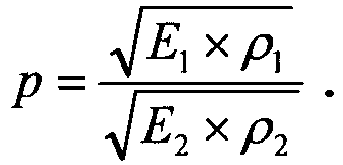
- Joint rotatif selon la revendication 7 ou 8, caractérisé par un rapport d'impédance (p) qui présente au moins la valeur 3, le rapport d'impédance (p) étant un quotient d'une racine carrée d'un produit du module d'élasticité (E1) et de la densité (ρ1) du matériau du chemin de roulement et de la racine carrée d'un produit du module d'élasticité (E2) et de la densité (ρ2) du matériau de la couche d'isolation, c'est-à-dire
- Joint rotatif selon au moins l'une quelconque des revendications 7 à 9, caractérisé par une couche d'isolation (11) constituée d'au moins un matériau élastomère.
- Joint rotatif selon au moins l'une quelconque des revendications précédentes, caractérisé par une bague de palier (8) au niveau de laquelle est réalisé le chemin de roulement (5).
- Joint rotatif selon au moins l'une quelconque des revendications précédentes, caractérisé en ce qu'au moins certains des corps de roulement (4) de la rangée sont en un matériau ayant une densité p < 5 g/cm3.
- Joint rotatif selon au moins l'une quelconque des revendications précédentes, caractérisé en ce qu'au moins certains des corps de roulement (4) de la rangée sont constitués d'un matériau isolant vis-à-vis du courant électrique, la résistance électrique spécifique du matériau étant supérieure à 1010 Ohm·mm2/m.
- Joint rotatif selon au moins l'une quelconque des revendications précédentes, caractérisé par un système de capteur (18) dans le joint rotatif (1), avec lequel au moins des positions relatives dans la direction périphérique entre un rotor (13) d'un moteur rotatif de l'unité d'entraînement (3) et le stator (15) du moteur rotatif peuvent être détectées, le rotor (13) étant accouplé de manière solidaire en rotation au chemin de roulement (5).
- Joint rotatif selon la revendication 14, caractérisé par une unité de régulation (22) accouplée au moteur rotatif et au système de capteur (18) pour convertir des signaux de sortie du système de capteur (18) en signaux d'entrée pour la régulation du moteur rotatif.
Applications Claiming Priority (2)
| Application Number | Priority Date | Filing Date | Title |
|---|---|---|---|
| US62754104P | 2004-11-12 | 2004-11-12 | |
| EP05810678A EP1809917A1 (fr) | 2004-11-12 | 2005-11-04 | Joint tournant |
Related Parent Applications (2)
| Application Number | Title | Priority Date | Filing Date |
|---|---|---|---|
| EP05810678A Division EP1809917A1 (fr) | 2004-11-12 | 2005-11-04 | Joint tournant |
| EP05810678.2 Division | 2005-11-04 |
Publications (3)
| Publication Number | Publication Date |
|---|---|
| EP1975426A2 EP1975426A2 (fr) | 2008-10-01 |
| EP1975426A3 EP1975426A3 (fr) | 2012-02-29 |
| EP1975426B1 true EP1975426B1 (fr) | 2017-09-06 |
Family
ID=35985245
Family Applications (3)
| Application Number | Title | Priority Date | Filing Date |
|---|---|---|---|
| EP08012885.3A Expired - Lifetime EP1975426B1 (fr) | 2004-11-12 | 2005-11-04 | Joint rotatif |
| EP08012884.6A Expired - Lifetime EP1975425B1 (fr) | 2004-11-12 | 2005-11-04 | Joint rotatif |
| EP05810678A Withdrawn EP1809917A1 (fr) | 2004-11-12 | 2005-11-04 | Joint tournant |
Family Applications After (2)
| Application Number | Title | Priority Date | Filing Date |
|---|---|---|---|
| EP08012884.6A Expired - Lifetime EP1975425B1 (fr) | 2004-11-12 | 2005-11-04 | Joint rotatif |
| EP05810678A Withdrawn EP1809917A1 (fr) | 2004-11-12 | 2005-11-04 | Joint tournant |
Country Status (6)
| Country | Link |
|---|---|
| US (1) | US8197145B2 (fr) |
| EP (3) | EP1975426B1 (fr) |
| JP (1) | JP4947557B2 (fr) |
| CN (3) | CN101865209B (fr) |
| RU (1) | RU2007115806A (fr) |
| WO (1) | WO2006050700A1 (fr) |
Families Citing this family (9)
| Publication number | Priority date | Publication date | Assignee | Title |
|---|---|---|---|---|
| EP2316342A1 (fr) * | 2009-09-18 | 2011-05-04 | Güdel Group AG | Système de support pour appareils à scanner |
| DE102011085884B4 (de) * | 2011-11-08 | 2021-10-21 | Zf Friedrichshafen Ag | Drehmomentübertragungseinrichtung mit elektrischer Isolierung |
| BR112014014728A2 (pt) * | 2011-12-20 | 2017-06-13 | Koninklijke Philips Nv | sistema de imagem; e método |
| JP2015094454A (ja) * | 2013-11-14 | 2015-05-18 | Ntn株式会社 | 回転センサ付き転がり軸受 |
| JP6618923B2 (ja) * | 2014-04-04 | 2019-12-11 | エルジー イノテック カンパニー リミテッド | モータ |
| CN105391246B (zh) * | 2015-12-04 | 2019-03-15 | 郑州宇通客车股份有限公司 | 一种电机及使用该电机的车辆 |
| US10655610B2 (en) | 2017-04-28 | 2020-05-19 | General Electric Company | Wire races for wind turbine bearings |
| EP3604839A1 (fr) | 2018-08-03 | 2020-02-05 | Ondal Medical Systems GmbH | Palier |
| DE102020201957A1 (de) * | 2020-02-17 | 2021-08-19 | Scanlab Gmbh | Galvanometerantrieb mit spielfreier Lagerung |
Family Cites Families (28)
| Publication number | Priority date | Publication date | Assignee | Title |
|---|---|---|---|---|
| DE2819366A1 (de) * | 1978-05-03 | 1979-11-15 | Voith Getriebe Kg | Lagerung fuer ein drehbares maschinenteil |
| DE3830386A1 (de) * | 1988-09-07 | 1990-03-15 | Kress Elektrik Gmbh & Co | Wellenlagerung fuer einen elektromotor und montageverfahren fuer diese |
| DE4221429C2 (de) * | 1991-07-01 | 1999-01-14 | Papst Motoren Gmbh & Co Kg | Plattenspeicherantrieb, insbesondere für Festplattenspeicher |
| US5456538A (en) * | 1993-08-04 | 1995-10-10 | Nsk Ltd. | Roller bearing |
| FR2708975B1 (fr) * | 1993-08-10 | 1995-11-03 | Gkn Cardantec | Palier intermédiaire pour des lignes d'arbres de transmission dans des véhicules automobiles. |
| JPH07208462A (ja) * | 1994-01-24 | 1995-08-11 | Ntn Corp | 絶縁転がり軸受 |
| DE4439690A1 (de) * | 1994-11-07 | 1996-05-09 | Philips Patentverwaltung | Induktionsmotor |
| US5782563A (en) * | 1995-03-10 | 1998-07-21 | Nsk Ltd. | Rolling bearing unit |
| JPH09291942A (ja) * | 1996-02-26 | 1997-11-11 | Nippon Seiko Kk | ラジアル転がり軸受 |
| DE19733261C2 (de) * | 1997-08-01 | 2001-07-19 | Dornier Gmbh Lindauer | Rotations-Kantendreher mit direkt elektromagnetischem Antrieb für Webmaschinen |
| CN2304783Y (zh) * | 1997-09-12 | 1999-01-20 | 国营二一○厂 | 微型同步电机转子柔性轴承 |
| DE19755563C1 (de) | 1997-12-13 | 1999-02-11 | Daimler Benz Ag | Mittellager für eine Welle |
| DE19834361A1 (de) * | 1998-07-30 | 2000-02-03 | Schaeffler Waelzlager Ohg | Bauteil, insbesondere Wälzlager- und Motorenbauteil |
| JP3385458B2 (ja) * | 1998-09-09 | 2003-03-10 | ミネベア株式会社 | スピンドルモータ |
| US6371653B2 (en) * | 1998-10-07 | 2002-04-16 | Minebea Co., Ltd. | Anti-friction bearing and a motor including such a bearing |
| EP1024295A1 (fr) * | 1999-01-27 | 2000-08-02 | Siemens Aktiengesellschaft | Entraínement pour moteur éléctrique |
| US6450689B1 (en) * | 1999-12-08 | 2002-09-17 | Tokyo Sunworker Co., Ltd. | Roller and method of producing the same |
| US6548929B2 (en) * | 2000-05-03 | 2003-04-15 | Horton, Inc. | Eddy current fan drive |
| DE10047592A1 (de) * | 2000-09-26 | 2002-04-25 | Siemens Ag | Lüftervorrichtung mit elektromagnetischer Kupplung |
| US6989618B2 (en) * | 2001-04-18 | 2006-01-24 | Nsk Ltd. | Rolling bearing with built-in motor |
| DE10125808A1 (de) * | 2001-05-26 | 2002-12-12 | Westfalia Separator Food Tec G | Zentrifugalseparator |
| DE10154705B4 (de) * | 2001-11-09 | 2005-07-07 | Carl Freudenberg Kg | Lager |
| DE10210071A1 (de) | 2002-03-08 | 2003-10-09 | Lat Suhl Ag | Drehmomentmotor in Segmentbauweise |
| JP2004141534A (ja) * | 2002-10-28 | 2004-05-20 | Hitachi Medical Corp | X線ct装置 |
| DE10393924B4 (de) * | 2002-12-16 | 2007-08-16 | Nsk Ltd. | Vierpunktkontakt-Kugellager |
| DE10326074B4 (de) * | 2003-06-10 | 2015-04-02 | Trw Automotive Electronics & Components Gmbh & Co. Kg | Elektromotorischer Antrieb, insbesondere für eine Pumpe für eine elektrohydraulische Fahrzeuglenkvorrichtung |
| DE102004047471A1 (de) * | 2004-09-30 | 2006-04-06 | Robert Bosch Gmbh | Verbindungseinrichtung |
| EP1736345A1 (fr) * | 2005-06-22 | 2006-12-27 | Zf Friedrichshafen Ag | Module d'entraînement à moteur électrique |
-
2005
- 2005-11-04 CN CN2010101135915A patent/CN101865209B/zh not_active Expired - Fee Related
- 2005-11-04 US US11/719,173 patent/US8197145B2/en not_active Expired - Fee Related
- 2005-11-04 RU RU2007115806/11A patent/RU2007115806A/ru not_active Application Discontinuation
- 2005-11-04 JP JP2007543689A patent/JP4947557B2/ja not_active Expired - Fee Related
- 2005-11-04 CN CN2010101136034A patent/CN101865207B/zh not_active Expired - Fee Related
- 2005-11-04 EP EP08012885.3A patent/EP1975426B1/fr not_active Expired - Lifetime
- 2005-11-04 EP EP08012884.6A patent/EP1975425B1/fr not_active Expired - Lifetime
- 2005-11-04 EP EP05810678A patent/EP1809917A1/fr not_active Withdrawn
- 2005-11-04 CN CN2005800385944A patent/CN101065588B/zh not_active Expired - Fee Related
- 2005-11-04 WO PCT/DE2005/001984 patent/WO2006050700A1/fr not_active Ceased
Non-Patent Citations (1)
| Title |
|---|
| None * |
Also Published As
| Publication number | Publication date |
|---|---|
| EP1809917A1 (fr) | 2007-07-25 |
| EP1975425A3 (fr) | 2012-02-29 |
| WO2006050700A1 (fr) | 2006-05-18 |
| JP4947557B2 (ja) | 2012-06-06 |
| US20090154865A1 (en) | 2009-06-18 |
| EP1975426A2 (fr) | 2008-10-01 |
| JP2008519955A (ja) | 2008-06-12 |
| CN101065588A (zh) | 2007-10-31 |
| CN101865207A (zh) | 2010-10-20 |
| CN101865209A (zh) | 2010-10-20 |
| US8197145B2 (en) | 2012-06-12 |
| EP1975426A3 (fr) | 2012-02-29 |
| EP1975425A2 (fr) | 2008-10-01 |
| EP1975425B1 (fr) | 2017-09-06 |
| CN101865209B (zh) | 2012-07-18 |
| CN101865207B (zh) | 2011-09-14 |
| RU2007115806A (ru) | 2008-10-27 |
| CN101065588B (zh) | 2010-09-01 |
Similar Documents
| Publication | Publication Date | Title |
|---|---|---|
| EP1975426B1 (fr) | Joint rotatif | |
| EP1478900B1 (fr) | Mecanisme de transmission et codeur de rotation equipe dudit mecanisme | |
| DE102017220662A1 (de) | Lageranordnung mit einem integrierten Generator | |
| EP2325654A1 (fr) | Palier à roulement avec capteur | |
| DE102019007667A1 (de) | Abtasteinheit für eine winkelmesseinrichtung | |
| WO2012152538A1 (fr) | Palier comprenant une unité génératrice d'énergie, en particulier un palier à rotule pour le support d'un rouleau | |
| DE10011820B4 (de) | Messeinrichtung für Wälzlager | |
| DE102004054974B4 (de) | Drehverbindung | |
| DE102016212925A1 (de) | Permanentmagnet für eine Sensoranordnung zur Bestimmung einer Winkelposition des Permanentmagneten | |
| DE102013227060A1 (de) | Drehrahmen für die Gantry eines Computertomographen, sowie Gantry und Computertomograph mit einem solchen Drehrahmen | |
| EP1593865B1 (fr) | Palier à roulement | |
| EP3683552A1 (fr) | Unité de balayage pour un dispositif de mesure d'angle | |
| DE102010020426A1 (de) | Elektrische Maschine, insbesondere für eine Windkraftanlage | |
| EP4334205A1 (fr) | Dispositif de propulsion pour propulser un véhicule aquatique | |
| EP1445061A2 (fr) | Plateau tournant avec plusieurs éléments moteurs | |
| DE102005056389A1 (de) | Lagerung | |
| EP1045507B1 (fr) | Moteur à rotor en forme de disque avec disque monté à rotation | |
| DE102007004647A1 (de) | Verfahren zur präzisen Erfassung der absoluten Winkelposition eines rotierbaren Bauteils | |
| DE102011076144A1 (de) | Elektromotor mit rotorwellenfest vorgespanntem Radialkugellager und Antriebseinheit eines Kraftfahrzeugs | |
| EP1696540B1 (fr) | Joint tournant | |
| JP4569363B2 (ja) | センサ付き転がり軸受装置 | |
| DE102010062480A1 (de) | Wälzlageranordnung mit einem Drehgeber | |
| WO2025196309A1 (fr) | Mécanisme d'engrenage à ondes de déformation | |
| WO2009121511A1 (fr) | Palier avec bague rotative mise à la terre | |
| DE102014018633A1 (de) | Elektrische Maschine |
Legal Events
| Date | Code | Title | Description |
|---|---|---|---|
| PUAI | Public reference made under article 153(3) epc to a published international application that has entered the european phase |
Free format text: ORIGINAL CODE: 0009012 |
|
| AC | Divisional application: reference to earlier application |
Ref document number: 1809917 Country of ref document: EP Kind code of ref document: P |
|
| AK | Designated contracting states |
Kind code of ref document: A2 Designated state(s): AT BE BG CH CY CZ DE DK EE ES FI FR GB GR HU IE IS IT LI LT LU LV MC NL PL PT RO SE SI SK TR |
|
| REG | Reference to a national code |
Ref country code: DE Ref legal event code: R079 Ref document number: 502005015707 Country of ref document: DE Free format text: PREVIOUS MAIN CLASS: F16C0019160000 Ipc: F16C0027060000 |
|
| PUAL | Search report despatched |
Free format text: ORIGINAL CODE: 0009013 |
|
| AK | Designated contracting states |
Kind code of ref document: A3 Designated state(s): AT BE BG CH CY CZ DE DK EE ES FI FR GB GR HU IE IS IT LI LT LU LV MC NL PL PT RO SE SI SK TR |
|
| RIC1 | Information provided on ipc code assigned before grant |
Ipc: F16C 41/00 20060101ALI20120126BHEP Ipc: F16C 27/06 20060101AFI20120126BHEP Ipc: F16C 19/06 20060101ALI20120126BHEP |
|
| RAP1 | Party data changed (applicant data changed or rights of an application transferred) |
Owner name: SCHAEFFLER TECHNOLOGIES AG & CO. KG |
|
| 17P | Request for examination filed |
Effective date: 20120829 |
|
| AKX | Designation fees paid |
Designated state(s): AT BE BG CH CY CZ DE DK EE ES FI FR GB GR HU IE IS IT LI LT LU LV MC NL PL PT RO SE SI SK TR |
|
| RAP1 | Party data changed (applicant data changed or rights of an application transferred) |
Owner name: SCHAEFFLER TECHNOLOGIES GMBH & CO. KG |
|
| RAP1 | Party data changed (applicant data changed or rights of an application transferred) |
Owner name: SCHAEFFLER TECHNOLOGIES AG & CO. KG |
|
| GRAP | Despatch of communication of intention to grant a patent |
Free format text: ORIGINAL CODE: EPIDOSNIGR1 |
|
| INTG | Intention to grant announced |
Effective date: 20170419 |
|
| GRAS | Grant fee paid |
Free format text: ORIGINAL CODE: EPIDOSNIGR3 |
|
| GRAA | (expected) grant |
Free format text: ORIGINAL CODE: 0009210 |
|
| AC | Divisional application: reference to earlier application |
Ref document number: 1809917 Country of ref document: EP Kind code of ref document: P |
|
| AK | Designated contracting states |
Kind code of ref document: B1 Designated state(s): AT BE BG CH CY CZ DE DK EE ES FI FR GB GR HU IE IS IT LI LT LU LV MC NL PL PT RO SE SI SK TR |
|
| REG | Reference to a national code |
Ref country code: GB Ref legal event code: FG4D Free format text: NOT ENGLISH |
|
| REG | Reference to a national code |
Ref country code: CH Ref legal event code: EP Ref country code: AT Ref legal event code: REF Ref document number: 926221 Country of ref document: AT Kind code of ref document: T Effective date: 20170915 |
|
| REG | Reference to a national code |
Ref country code: IE Ref legal event code: FG4D Free format text: LANGUAGE OF EP DOCUMENT: GERMAN |
|
| REG | Reference to a national code |
Ref country code: DE Ref legal event code: R096 Ref document number: 502005015707 Country of ref document: DE |
|
| REG | Reference to a national code |
Ref country code: FR Ref legal event code: PLFP Year of fee payment: 13 |
|
| REG | Reference to a national code |
Ref country code: NL Ref legal event code: MP Effective date: 20170906 |
|
| REG | Reference to a national code |
Ref country code: LT Ref legal event code: MG4D |
|
| PG25 | Lapsed in a contracting state [announced via postgrant information from national office to epo] |
Ref country code: SE Free format text: LAPSE BECAUSE OF FAILURE TO SUBMIT A TRANSLATION OF THE DESCRIPTION OR TO PAY THE FEE WITHIN THE PRESCRIBED TIME-LIMIT Effective date: 20170906 Ref country code: LT Free format text: LAPSE BECAUSE OF FAILURE TO SUBMIT A TRANSLATION OF THE DESCRIPTION OR TO PAY THE FEE WITHIN THE PRESCRIBED TIME-LIMIT Effective date: 20170906 Ref country code: FI Free format text: LAPSE BECAUSE OF FAILURE TO SUBMIT A TRANSLATION OF THE DESCRIPTION OR TO PAY THE FEE WITHIN THE PRESCRIBED TIME-LIMIT Effective date: 20170906 |
|
| PGFP | Annual fee paid to national office [announced via postgrant information from national office to epo] |
Ref country code: FR Payment date: 20171129 Year of fee payment: 13 |
|
| PG25 | Lapsed in a contracting state [announced via postgrant information from national office to epo] |
Ref country code: LV Free format text: LAPSE BECAUSE OF FAILURE TO SUBMIT A TRANSLATION OF THE DESCRIPTION OR TO PAY THE FEE WITHIN THE PRESCRIBED TIME-LIMIT Effective date: 20170906 Ref country code: GR Free format text: LAPSE BECAUSE OF FAILURE TO SUBMIT A TRANSLATION OF THE DESCRIPTION OR TO PAY THE FEE WITHIN THE PRESCRIBED TIME-LIMIT Effective date: 20171207 Ref country code: BG Free format text: LAPSE BECAUSE OF FAILURE TO SUBMIT A TRANSLATION OF THE DESCRIPTION OR TO PAY THE FEE WITHIN THE PRESCRIBED TIME-LIMIT Effective date: 20171206 Ref country code: ES Free format text: LAPSE BECAUSE OF FAILURE TO SUBMIT A TRANSLATION OF THE DESCRIPTION OR TO PAY THE FEE WITHIN THE PRESCRIBED TIME-LIMIT Effective date: 20170906 |
|
| PGFP | Annual fee paid to national office [announced via postgrant information from national office to epo] |
Ref country code: IT Payment date: 20171124 Year of fee payment: 13 Ref country code: GB Payment date: 20171130 Year of fee payment: 13 |
|
| PG25 | Lapsed in a contracting state [announced via postgrant information from national office to epo] |
Ref country code: NL Free format text: LAPSE BECAUSE OF FAILURE TO SUBMIT A TRANSLATION OF THE DESCRIPTION OR TO PAY THE FEE WITHIN THE PRESCRIBED TIME-LIMIT Effective date: 20170906 |
|
| PG25 | Lapsed in a contracting state [announced via postgrant information from national office to epo] |
Ref country code: CZ Free format text: LAPSE BECAUSE OF FAILURE TO SUBMIT A TRANSLATION OF THE DESCRIPTION OR TO PAY THE FEE WITHIN THE PRESCRIBED TIME-LIMIT Effective date: 20170906 Ref country code: RO Free format text: LAPSE BECAUSE OF FAILURE TO SUBMIT A TRANSLATION OF THE DESCRIPTION OR TO PAY THE FEE WITHIN THE PRESCRIBED TIME-LIMIT Effective date: 20170906 Ref country code: PL Free format text: LAPSE BECAUSE OF FAILURE TO SUBMIT A TRANSLATION OF THE DESCRIPTION OR TO PAY THE FEE WITHIN THE PRESCRIBED TIME-LIMIT Effective date: 20170906 |
|
| PGFP | Annual fee paid to national office [announced via postgrant information from national office to epo] |
Ref country code: DE Payment date: 20180131 Year of fee payment: 13 |
|
| PG25 | Lapsed in a contracting state [announced via postgrant information from national office to epo] |
Ref country code: SK Free format text: LAPSE BECAUSE OF FAILURE TO SUBMIT A TRANSLATION OF THE DESCRIPTION OR TO PAY THE FEE WITHIN THE PRESCRIBED TIME-LIMIT Effective date: 20170906 Ref country code: IS Free format text: LAPSE BECAUSE OF FAILURE TO SUBMIT A TRANSLATION OF THE DESCRIPTION OR TO PAY THE FEE WITHIN THE PRESCRIBED TIME-LIMIT Effective date: 20180106 Ref country code: EE Free format text: LAPSE BECAUSE OF FAILURE TO SUBMIT A TRANSLATION OF THE DESCRIPTION OR TO PAY THE FEE WITHIN THE PRESCRIBED TIME-LIMIT Effective date: 20170906 |
|
| REG | Reference to a national code |
Ref country code: DE Ref legal event code: R097 Ref document number: 502005015707 Country of ref document: DE |
|
| PG25 | Lapsed in a contracting state [announced via postgrant information from national office to epo] |
Ref country code: MC Free format text: LAPSE BECAUSE OF FAILURE TO SUBMIT A TRANSLATION OF THE DESCRIPTION OR TO PAY THE FEE WITHIN THE PRESCRIBED TIME-LIMIT Effective date: 20170906 |
|
| PLBE | No opposition filed within time limit |
Free format text: ORIGINAL CODE: 0009261 |
|
| STAA | Information on the status of an ep patent application or granted ep patent |
Free format text: STATUS: NO OPPOSITION FILED WITHIN TIME LIMIT |
|
| PG25 | Lapsed in a contracting state [announced via postgrant information from national office to epo] |
Ref country code: LI Free format text: LAPSE BECAUSE OF NON-PAYMENT OF DUE FEES Effective date: 20171130 Ref country code: CH Free format text: LAPSE BECAUSE OF NON-PAYMENT OF DUE FEES Effective date: 20171130 Ref country code: DK Free format text: LAPSE BECAUSE OF FAILURE TO SUBMIT A TRANSLATION OF THE DESCRIPTION OR TO PAY THE FEE WITHIN THE PRESCRIBED TIME-LIMIT Effective date: 20170906 |
|
| 26N | No opposition filed |
Effective date: 20180607 |
|
| PG25 | Lapsed in a contracting state [announced via postgrant information from national office to epo] |
Ref country code: SI Free format text: LAPSE BECAUSE OF FAILURE TO SUBMIT A TRANSLATION OF THE DESCRIPTION OR TO PAY THE FEE WITHIN THE PRESCRIBED TIME-LIMIT Effective date: 20170906 Ref country code: LU Free format text: LAPSE BECAUSE OF NON-PAYMENT OF DUE FEES Effective date: 20171104 |
|
| REG | Reference to a national code |
Ref country code: BE Ref legal event code: MM Effective date: 20171130 |
|
| REG | Reference to a national code |
Ref country code: IE Ref legal event code: MM4A |
|
| PG25 | Lapsed in a contracting state [announced via postgrant information from national office to epo] |
Ref country code: IE Free format text: LAPSE BECAUSE OF NON-PAYMENT OF DUE FEES Effective date: 20171104 |
|
| PG25 | Lapsed in a contracting state [announced via postgrant information from national office to epo] |
Ref country code: BE Free format text: LAPSE BECAUSE OF NON-PAYMENT OF DUE FEES Effective date: 20171130 |
|
| REG | Reference to a national code |
Ref country code: AT Ref legal event code: MM01 Ref document number: 926221 Country of ref document: AT Kind code of ref document: T Effective date: 20171104 |
|
| PG25 | Lapsed in a contracting state [announced via postgrant information from national office to epo] |
Ref country code: AT Free format text: LAPSE BECAUSE OF NON-PAYMENT OF DUE FEES Effective date: 20171104 |
|
| REG | Reference to a national code |
Ref country code: DE Ref legal event code: R119 Ref document number: 502005015707 Country of ref document: DE |
|
| PG25 | Lapsed in a contracting state [announced via postgrant information from national office to epo] |
Ref country code: HU Free format text: LAPSE BECAUSE OF FAILURE TO SUBMIT A TRANSLATION OF THE DESCRIPTION OR TO PAY THE FEE WITHIN THE PRESCRIBED TIME-LIMIT; INVALID AB INITIO Effective date: 20051104 |
|
| GBPC | Gb: european patent ceased through non-payment of renewal fee |
Effective date: 20181104 |
|
| PG25 | Lapsed in a contracting state [announced via postgrant information from national office to epo] |
Ref country code: FR Free format text: LAPSE BECAUSE OF NON-PAYMENT OF DUE FEES Effective date: 20181130 Ref country code: DE Free format text: LAPSE BECAUSE OF NON-PAYMENT OF DUE FEES Effective date: 20190601 Ref country code: CY Free format text: LAPSE BECAUSE OF NON-PAYMENT OF DUE FEES Effective date: 20170906 Ref country code: IT Free format text: LAPSE BECAUSE OF NON-PAYMENT OF DUE FEES Effective date: 20181104 |
|
| PG25 | Lapsed in a contracting state [announced via postgrant information from national office to epo] |
Ref country code: GB Free format text: LAPSE BECAUSE OF NON-PAYMENT OF DUE FEES Effective date: 20181104 |
|
| PG25 | Lapsed in a contracting state [announced via postgrant information from national office to epo] |
Ref country code: TR Free format text: LAPSE BECAUSE OF FAILURE TO SUBMIT A TRANSLATION OF THE DESCRIPTION OR TO PAY THE FEE WITHIN THE PRESCRIBED TIME-LIMIT Effective date: 20170906 |
|
| PG25 | Lapsed in a contracting state [announced via postgrant information from national office to epo] |
Ref country code: PT Free format text: LAPSE BECAUSE OF FAILURE TO SUBMIT A TRANSLATION OF THE DESCRIPTION OR TO PAY THE FEE WITHIN THE PRESCRIBED TIME-LIMIT Effective date: 20170906 |
|
| P01 | Opt-out of the competence of the unified patent court (upc) registered |
Effective date: 20230524 |