EP1976331B1 - A separate support structure for a loudspeaker diaphragm - Google Patents
A separate support structure for a loudspeaker diaphragm Download PDFInfo
- Publication number
- EP1976331B1 EP1976331B1 EP06805232.3A EP06805232A EP1976331B1 EP 1976331 B1 EP1976331 B1 EP 1976331B1 EP 06805232 A EP06805232 A EP 06805232A EP 1976331 B1 EP1976331 B1 EP 1976331B1
- Authority
- EP
- European Patent Office
- Prior art keywords
- diaphragm
- curved
- loudspeaker
- support structure
- elastic body
- Prior art date
- Legal status (The legal status is an assumption and is not a legal conclusion. Google has not performed a legal analysis and makes no representation as to the accuracy of the status listed.)
- Not-in-force
Links
Images


Classifications
-
- H—ELECTRICITY
- H04—ELECTRIC COMMUNICATION TECHNIQUE
- H04R—LOUDSPEAKERS, MICROPHONES, GRAMOPHONE PICK-UPS OR LIKE ACOUSTIC ELECTROMECHANICAL TRANSDUCERS; ELECTRIC HEARING AIDS; PUBLIC ADDRESS SYSTEMS
- H04R7/00—Diaphragms for electromechanical transducers; Cones
- H04R7/16—Mounting or tensioning of diaphragms or cones
- H04R7/18—Mounting or tensioning of diaphragms or cones at the periphery
- H04R7/20—Securing diaphragm or cone resiliently to support by flexible material, springs, cords, or strands
-
- H—ELECTRICITY
- H04—ELECTRIC COMMUNICATION TECHNIQUE
- H04R—LOUDSPEAKERS, MICROPHONES, GRAMOPHONE PICK-UPS OR LIKE ACOUSTIC ELECTROMECHANICAL TRANSDUCERS; ELECTRIC HEARING AIDS; PUBLIC ADDRESS SYSTEMS
- H04R2307/00—Details of diaphragms or cones for electromechanical transducers, their suspension or their manufacture covered by H04R7/00 or H04R31/003, not provided for in any of its subgroups
- H04R2307/204—Material aspects of the outer suspension of loudspeaker diaphragms
-
- H—ELECTRICITY
- H04—ELECTRIC COMMUNICATION TECHNIQUE
- H04R—LOUDSPEAKERS, MICROPHONES, GRAMOPHONE PICK-UPS OR LIKE ACOUSTIC ELECTROMECHANICAL TRANSDUCERS; ELECTRIC HEARING AIDS; PUBLIC ADDRESS SYSTEMS
- H04R2307/00—Details of diaphragms or cones for electromechanical transducers, their suspension or their manufacture covered by H04R7/00 or H04R31/003, not provided for in any of its subgroups
- H04R2307/207—Shape aspects of the outer suspension of loudspeaker diaphragms
Definitions
- the invention relates to the field of electroacoustical technology, more specially to a support structure for positioning of a diaphragm in a loudspeaker and keeping vibration of the diaphragm.
- the present invention relates to a separate kind of support structure for the diaphragm.
- Diaphragms used in most of the cone and dome loudspeaker in the present market are supported by means of a fold-ring (some including a centering tab), the fold-ring supports the diaphragm so that the diaphragm vibrates under the action of a electroacoustical driving force to output the sound, and the fold-ring and the diaphragm form an integral structure.
- Some fold-rings and diaphragms are made of same material, both being an integral structure; some fold-rings and diaphragms are made of different materials, both also being an integral structure by bonder means.
- an aluminum ribbon diaphragm with thickness in the range of about 0.006-0.02mm is generally used, which is constructed as corrugation to support and keep the vibration of the diaphragm.
- this loudspeaker is an excellent high-pitch unit
- the corrugated aluminum ribbon diaphragm is susceptible to slack when it is operated by an electromagnetic force in long term and other strong external force.
- the diaphragm may become elongated and offset the center area of the magnetic clearance so as to generate distortion at work, the problem concerning the reliability and service life is hard to be resolved over a long time of period.
- the diaphragm is a compound plastic-aluminium-Toll diaphragm, which is made of the film such as polyester and polyimide as the basic material by means of flexible circuit board technology.
- the planar-fllm diaphragm vibrates with the help of the elasticity generated by the plastic film between the retain ring around the plantar-film diaphragm and the flexible circuit board.
- the elastic retain ring of the planar-film diaphragm must have a predetermined width, which results in increasing the total area of the diaphragm of the planar-film loudspeaker.
- the above mentioned support structure of the three diaphragm has a common character that the support structure and the diaphragm are formed as an integral piece.
- This kind structure has a certain limitation in technology
- CH 140 769 discloses a loudspeaker wherein the diaphragm, that is strengthened at its border by a groove, is supported by means of cotton wool, so that the diaphragm is neither completely free nor completely fixedly fastened.
- EP 0119 897 discloses means for fastening a piezoelectric diaphragm, e.g. in accelerometers.
- the diaphragm is fixed in such a way that it cannot move with respect to the fastening means when large temperature variations arise.
- the object of the invention is to overcome the drawbacks above mentioned in the prior art, and to improve the performance of loudspeaker.
- the invention is defined by the appendent claims.
- the loudspeaker diaphragm according to the invention is a separate kind of support structure, this support structure is used for positioning the loudspeaker diaphragm and keeping the vibration of diaphragm, wherein the support structure comprises: a first elastic body which has a first engaged face having a curved-surface shape; and a second elastic body which has a second engaged face, a curved-surface shape of the second engaged face complementarily matches the curved-surface shape of the first engaged face; the first engaged face of the first elastic body and the second engaged face of the second elastic body engage each other to clamp a supported portion of the loudspeaker diaphragm in opposite relation from two sides of the supported portion.
- the elastic bodies clamp the supported portion of the diaphragm by means of the engaged faces to keep supporting, there is no other connecting means such as an adhesive or the like between the elastic body and the diaphragm, hence a separate support structure is formed between the supported portion of the diaphragm and the curved-surface elastic body.
- the curved-surface elastic bodies support and locate the diaphragm in a center work area for diaphragm with the supported portion, in work state the diaphragm keeps vibrating at the corresponding amplitude with the audio signal.
- the loudspeaker diaphragm may be flexible or rigid.
- the separate support structure according to the invention eliminates the fold-ring to reduce the vibrating mass, which is particularly important for playing high frequency signal. Furthermore when the support structure of the present invention is applied to the ribbon loudspeaker and the planar-film loudspeaker, it may overcome the deficiency of the insufficient elastic deformation of the diaphragm material itself.
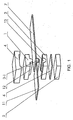
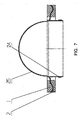
- Fig 1 there is shown a separate support structure for the loudspeaker diaphragm according to the invention, and this kind of support structure is used for retaining the positioning of the diaphragm and keeping the vibration of the loudspeaker diaphragm.
- the support structure includes a first curved-surface elastic body 1, a second curved-surface elastic body 2 and a supported portion 3-1 of the loudspeaker diaphragm.
- the first curved-surface elastic body 1 has a first engaged face 12 with a convex curved-surface shape
- the second curved-surface elastic body 2 has a second engaged face 13 with a concave curved-surface shape which is complementary to the curved-surface shape of the first curved-surface elastic body.
- the first engaged face 12 of the first curved-surface elastic body and the second engaged face 13 of the second curved-surface elastic body engage oppositely from both sides of the supported portion 3-1 of the loudspeaker diaphragm 7 and clamp the supported portion 3-1. It should be noted that there is no any connection means, such as an adhesive, between the first engaged face and the second engaged face, which is particularly benefit to the loudspeaker performance.
- the diaphragm for the loudspeaker is a flexible diaphragm 7.
- the supported portion 3-1 of the diaphragm is sandwiched between both engaged faces of the two curved-surface elastic bodies 1 and 2, for example, the flexible diaphragm 7 may be a ribbon diaphragm for the ribbon loudspeaker or a planar-film diaphragm for the planar-film loudspeaker.
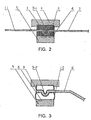
- a first fixation member for connecting to the curved-surface elastic body is denoted by reference numeral 4 in Fig. 2 , the first curved elastic body 1 is fixed in the first fixation member 4 by means of insertion.
- a second fixation member for connecting to the curved-surface elastic body is denoted by the reference numeral 5, as shown in the figure, the second curved-surface elastic body 2 is fixed in the second fixation member 5 by means of an adhesive layer 6.
- the connection means between the fixation members and the elastic bodies is not limited, and the connection means may be selected according to the operation environment and manufacture technology.
- the first and second curved-surface elastic bodies 1, 2 may be made of macromolecular resilient material, such as rubber, polyamino-rubber etc.
- the elastic bodies may preferably be made from thermal-resistant resilient material of macromolecule, such as fluo-rubber, silicon rubber etc, since the current flows through the conductive circuit in the diaphragm and the temperature may arise up to 100°C or above under a maximum power.
- the support structure shown in Fig. 2 is the combination of the curved-surface elastic body and the supported portion in the ribbon loudspeaker and the planar-film loudspeaker which comprise the flexible diaphragm.
- the flexible diaphragm has a fixed section or a fixed area where the diaphragm is fixedly connected to a loudspeaker body so as to fix the diaphragm; the separate support structure formed by the curved-surface elastic bodies serves to support and tension the flexible diaphragm so that the diaphragm is positioned at a center working region.
- both the engaged faces of the two curved-surface elastic bodies open or close so that the diaphragm can stretch or withdraw; the separate support structure supports and keeps the diaphragm vibrating within a predetermined amplitude, while ensures that the vibration of the diaphragm does not exceed an elasticity limit.
- the position of the curved-surface elastic bodies 1, 2 is generally provided in the inside of the fixed section of ribbon diaphragm, and the elastic body may be provided on either end or both ends of the ribbon diaphragm.
- the extra-long ribbon loudspeaker diaphragm and the support structure of the curved-surface elastic body shown in fig. 8 if the length of the ribbon diaphragm is longer than 300 mm in the extra-long ribbon loudspeaker as shown in the figure, one pair or more pairs of curved-surface elastic bodies may be arranged at the middle of the diaphragm in order to further support and stabilize the flexible diaphragm.
- the position of the separate support structure including curved-surface elastic bodies 1 and 2 is generally between a flexible conductive circuit 27 and a retaining ring of the diaphragm.
- the minimum curvature radius of the first curved-surface elastic body I and the second curved-surface elastic body 2 is larger than or equal to the minimum allowable flex radius of the flexible diaphragm 7.
- the difference between a length of a curved-surface line of a section plane of the first and second elastic bodies and a length of a straight line of the section plane of the first and second elastic bodies is larger than or equal to the difference between a line length of the diaphragm at its maximum amplitude and a line length of the diaphragm at minimum amplitude.
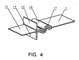
- Fig. 3 shows the support structure of the loudspeaker diaphragm according to the second embodiment of the present invention.
- the structure shown in Fig. 3 is also a separate support structure for the loudspeaker diaphragm.
- the loudspeaker diaphragm in Fig. 3 is a rigid diaphragm 8, which has a rigid supported portion 3-2.
- the first curved-surface elastic body 9 and the second curved-surface elastic body 10 are both hollow elastic pieces, which are made of resilient material of macromolecule.
- the supported portion 3-2 of the rigid diaphragm 8 is sandwiched between the first engaged face of the first curved-surface elastic body 9 and the second engaged face of the second curved-surface elastic body 10 so that it is able to support and retain the loudspeaker diaphragm.
- the first hollow curved-surface elastic body 9 has a convex curved-surface shape and the second hollow curved-surface elastic body 10 has a concave curved-surface shape
- the both curved-surface faces of the elastic bodies 9 and 10 engage and match each other
- the supported portion 3-2 of the rigid diaphragm is sandwiched between the two complementary curved surfaces
- the supported portion 3-2 of the rigid diaphragm has a suitable shape that matches with the curved surfaces of the curved-surface elastic bodies 9, 10.
- the hollow curved-surface elastic bodies may be configured in a drum structure.
- the supported portion 3-2 of the rigid diaphragm and the first and second elastic bodies 9, 10 form as a separate structure, that is, there is no any connection means, such as an adhesive, between them.
- the first curved-surface elastic body 9 is fixed in the first fixation member 4 by means of insertion, while the second elastic body 10 is fixed in the second fixation member 5 by means of an adhesive.
- the connection means between the fixation member and the elastic bodies is not limited, and the connection means may be selected according to the operation environment and manufacture technology.
- the separate support structure shown in Fig. 3 is the combination of rigid supported portion 3-2 and the curved-surface elastic bodies 9, 10, this kind of support structure can subject to vibration and maintain its curved shape.
- the support structure of curved-surface elastic body allows the rigid diaphragm to vibrate under a driving force in the direction of the vertical axis (perpendicular to a plane of the diaphragm), and the support structure with the curved-surface elastic bodies can further stabilize the radial position of the rigid diaphragm.
- the minimum resilient displacement of the elastic body is larger than or equal to the maximum vibration amplitude of the loudspeaker diaphragm.
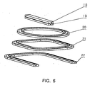
- Figure 4 shows a support structure of metallic thin plate for a diaphragm according to the third embodiment of the present invention.
- the support structure includes a first metallic curved-surface elastic body 16 having a first engaged face and a second metallic curved-surface elastic body 17 having a second engaged face, the engaged faces of the two metallic curved-surface elastic bodies 16 and 17 have S-shape curved matching surfaces, a diaphragm is sandwiched between the two engaged faces which are complementarily matched together.
- the separate support structure is formed of the supported portion and the first and second elastic bodies 16, 17, that is, there is no connection means, such as an adhesive, between them.
- the first and second metallic curved-surface elastic bodies have fixation sections 14 and 15 for the elastic bodies, respectively, so that they may be connected to the loudspeaker body by means of welding, a fastener, or an insertion slot.
- the flexible diaphragm 7 is sandwiched between the metallic curved-surface elastic bodies.
- the metallic curved-surface elastic bodies can support and maintain the positioning of the rigid diaphragm and keep its vibration as well.
- the metallic curved-surface elastic body may be made of material such as phosphor bronze and beryllium copper, etc.
- the curved-surface shape of the elastic body in the support structure may be various, for example in the shapes of waveform, sinusoidal waveform, S-form, V- form, U- form, C- form, M-form, W-form and so on.
- the separate support structure according to the invention may be not only used in the loudspeaker having the flexible diaphragm, such as the ribbon loudspeaker, planar-film loudspeaker as well as the dome-section high-pitch loudspeaker; but also may be used in the loudspeaker having the rigid diaphragm, such as the cone loudspeaker as shown in Fig. 6 and the dome high-pitch loudspeaker as shown in Fig. 7 .
- a cone diaphragm 23 in the cone loudspeaker is sandwiched and fixed between the first curved-surface elastic body 1 and the second curved-surface elastic body 2;
- a dome diaphragm 25 in the dome high-pitch loudspeaker is sandwiched and fixed between the first curved-surface elastic body 1 and the second curved-surface elastic body 2.
- the entire configuration of the elastic body may have many embodiments according to the type of the loudspeaker and the diaphragm structure.
- Fig. 5 shows some configurations, wherein reference numerals 18 and 19 show a bar-shaped curved-surface elastic body, reference numeral 20 shows a circular curved-surface elastic body, reference numeral 21 shows a square curved-surface elastic body with rounded corner, and reference numeral 22 shows a U-shaped curved-surface elastic body.
- the elliptical shape may also be adopted as the entire shape.
- the hollow curved-surface elastic body can be used in combination with the flexible diaphragm, or the solid curved-surface elastic body can be used in combination with the rigid diaphragm.
- the scope for protection of the invention is determined by the attached claims.
Landscapes
- Engineering & Computer Science (AREA)
- Multimedia (AREA)
- Physics & Mathematics (AREA)
- Acoustics & Sound (AREA)
- Signal Processing (AREA)
- Diaphragms For Electromechanical Transducers (AREA)
Applications Claiming Priority (2)
| Application Number | Priority Date | Filing Date | Title |
|---|---|---|---|
| CN2005101124943A CN1992996B (zh) | 2005-12-30 | 2005-12-30 | 扬声器振膜的分体式支承结构 |
| PCT/CN2006/003047 WO2007076677A1 (en) | 2005-12-30 | 2006-11-13 | A separate support structure for loudspeaker diaphragm |
Publications (3)
| Publication Number | Publication Date |
|---|---|
| EP1976331A1 EP1976331A1 (en) | 2008-10-01 |
| EP1976331A4 EP1976331A4 (en) | 2010-03-03 |
| EP1976331B1 true EP1976331B1 (en) | 2013-12-11 |
Family
ID=38214842
Family Applications (1)
| Application Number | Title | Priority Date | Filing Date |
|---|---|---|---|
| EP06805232.3A Not-in-force EP1976331B1 (en) | 2005-12-30 | 2006-11-13 | A separate support structure for a loudspeaker diaphragm |
Country Status (5)
| Country | Link |
|---|---|
| US (1) | US8094863B2 (da) |
| EP (1) | EP1976331B1 (da) |
| CN (1) | CN1992996B (da) |
| DK (1) | DK1976331T3 (da) |
| WO (1) | WO2007076677A1 (da) |
Families Citing this family (22)
| Publication number | Priority date | Publication date | Assignee | Title |
|---|---|---|---|---|
| CN1992996B (zh) * | 2005-12-30 | 2012-02-29 | 丁轶 | 扬声器振膜的分体式支承结构 |
| KR100902895B1 (ko) * | 2006-06-29 | 2009-06-15 | 엘지전자 주식회사 | 스피커 |
| FR2955444B1 (fr) | 2010-01-15 | 2012-08-03 | Phl Audio | Systeme de haut-parleur coaxial a chambre de compression |
| FR2955446B1 (fr) * | 2010-01-15 | 2015-06-05 | Phl Audio | Transducteur electrodynamique a dome et suspension flottante |
| FR2955445B1 (fr) | 2010-01-15 | 2013-06-07 | Phl Audio | Transducteur electrodynamique a dome et suspension interne |
| CN101959103B (zh) * | 2010-04-19 | 2016-06-08 | 瑞声声学科技(深圳)有限公司 | 振膜和包括该振膜的麦克风 |
| CN102572656B (zh) * | 2010-12-30 | 2016-06-22 | Ask工业S.P.A. | 带式扬声器 |
| ITAN20110030A1 (it) * | 2011-03-03 | 2012-09-04 | Ask Ind Societa Per Azioni | Trasduttore a nastro provvisto di sistema di tensionamento dinamico. |
| CN102761810B (zh) * | 2011-04-26 | 2015-04-08 | 歌尔声学股份有限公司 | 一种扬声器 |
| JP6253101B2 (ja) * | 2014-05-20 | 2017-12-27 | 株式会社オーディオテクニカ | 動電型電気音響変換器、及びその振動板、並びに動電型電気音響変換器の製造方法 |
| CN105246006A (zh) * | 2014-07-07 | 2016-01-13 | 张百良 | 具有各向异性顺性的扬声器和被动辐射器的悬边 |
| CN204578765U (zh) * | 2015-03-30 | 2015-08-19 | 歌尔声学股份有限公司 | 一种振膜和扬声器单体 |
| US9668057B1 (en) * | 2016-04-04 | 2017-05-30 | Richard Allen Jayne | Ribbon transducer |
| CN106851492A (zh) * | 2017-02-23 | 2017-06-13 | 安庆市信华电子机械有限公司 | 一种振膜固定组件 |
| CN107645698B (zh) * | 2017-10-10 | 2020-11-24 | 歌尔股份有限公司 | 用于发声装置的振膜的膜材和振膜 |
| EP3701727A1 (en) * | 2017-10-23 | 2020-09-02 | Hugh Brogan | An improved speaker |
| CN110324761A (zh) * | 2018-03-30 | 2019-10-11 | 昆山康龙电子科技有限公司 | 二物件之间的弹性构造 |
| CN110324762A (zh) * | 2018-03-30 | 2019-10-11 | 昆山康龙电子科技有限公司 | 用于制造两个对象之间的弹性结构的方法 |
| CN109391888A (zh) * | 2018-12-12 | 2019-02-26 | 陈伟东 | 扬声器结构、带式扬声器及音响设备 |
| CN110784806B (zh) * | 2019-10-31 | 2021-11-16 | 歌尔股份有限公司 | 一种用于微型发声装置的振膜及微型发声装置 |
| CN112243189A (zh) * | 2020-11-16 | 2021-01-19 | 无锡杰夫电声股份有限公司 | 一种超高频率扬声器 |
| CN114989615B (zh) * | 2022-05-25 | 2023-12-22 | 歌尔股份有限公司 | 发声装置的振膜及其制备方法、发声装置 |
Family Cites Families (33)
| Publication number | Priority date | Publication date | Assignee | Title |
|---|---|---|---|---|
| US1857794A (en) * | 1929-08-03 | 1932-05-10 | Bell Telephone Labor Inc | Wave energy translating diaphragm and method of mounting it |
| CH140769A (de) * | 1929-08-14 | 1930-06-30 | Horny Radiohaus | Lautsprecher. |
| JPS5379525A (en) * | 1976-12-23 | 1978-07-14 | Sony Corp | Compound diaphtagm for speakers |
| FR2542553A1 (fr) * | 1983-03-07 | 1984-09-14 | Thomson Csf | Dispositif d'encastrement d'un diaphragme piezo-electrique, son procede de realisation et transducteur electromecanique utilisant un tel dispositif |
| US4703658A (en) * | 1986-06-18 | 1987-11-03 | Motorola, Inc. | Pressure sensor assembly |
| JPH0715793A (ja) * | 1993-06-28 | 1995-01-17 | Sony Corp | スピーカ用振動板及びその成形方法 |
| JP3192100B2 (ja) * | 1996-11-08 | 2001-07-23 | 株式会社オーディオテクニカ | マイクロホン |
| JPH11275690A (ja) * | 1998-03-26 | 1999-10-08 | Sony Corp | スピーカ |
| EP1206897A2 (en) | 1999-07-23 | 2002-05-22 | Digital Sonics, Llc | Flat panel speaker |
| US20020126867A1 (en) * | 2001-03-07 | 2002-09-12 | Eliezer Aizik | Flexible ribbon speaker |
| US6577742B1 (en) * | 2001-05-24 | 2003-06-10 | Paul F. Bruney | Membrane support system |
| JP2003153378A (ja) * | 2001-11-15 | 2003-05-23 | Sony Corp | スピーカ装置 |
| JP3916997B2 (ja) * | 2002-04-30 | 2007-05-23 | スター精密株式会社 | 電気音響変換器 |
| ATE329474T1 (de) * | 2002-08-16 | 2006-06-15 | Koninkl Philips Electronics Nv | Lautsprecher mit umgekehrtem konus |
| US6967431B2 (en) * | 2002-12-13 | 2005-11-22 | Palo Alto Research Center Inc. | Piezoelectric transducers and methods of manufacture |
| US6987348B2 (en) * | 2002-12-13 | 2006-01-17 | Palo Alto Research Center Inc. | Piezoelectric transducers |
| JP3979334B2 (ja) * | 2003-04-21 | 2007-09-19 | 株式会社村田製作所 | 圧電型電気音響変換器 |
| JP2005167315A (ja) * | 2003-11-28 | 2005-06-23 | Pioneer Electronic Corp | スピーカユニット |
| KR100533716B1 (ko) * | 2003-12-05 | 2005-12-05 | 신정열 | 수평진동 보이스코일을 구비하는 판형 스피커 |
| JP4475993B2 (ja) * | 2004-03-22 | 2010-06-09 | 並木精密宝石株式会社 | 多機能型振動アクチュエータ及び携帯端末機器 |
| KR100547357B1 (ko) * | 2004-03-30 | 2006-01-26 | 삼성전기주식회사 | 휴대단말기용 스피커 및 그 제조방법 |
| CN2733798Y (zh) * | 2004-06-09 | 2005-10-12 | 丁轶 | 带式扬声器 |
| JP4626462B2 (ja) * | 2005-09-21 | 2011-02-09 | パナソニック株式会社 | スピーカ |
| JP4735405B2 (ja) * | 2005-09-21 | 2011-07-27 | パナソニック株式会社 | スピーカ用ダンパーとそれを用いたスピーカ |
| EP1768447A3 (en) * | 2005-09-21 | 2010-06-02 | Sonion Horsens A/S | Insert molded surround with mechanical support |
| JP2007110209A (ja) * | 2005-10-11 | 2007-04-26 | Matsushita Electric Ind Co Ltd | スピーカ |
| CN1992996B (zh) * | 2005-12-30 | 2012-02-29 | 丁轶 | 扬声器振膜的分体式支承结构 |
| JP4735299B2 (ja) * | 2006-02-06 | 2011-07-27 | パナソニック株式会社 | スピーカ |
| US8672648B2 (en) * | 2006-05-23 | 2014-03-18 | Nuventix, Inc. | Methods for reducing the non-linear behavior of actuators used for synthetic jets |
| WO2009044506A1 (ja) * | 2007-10-05 | 2009-04-09 | Panasonic Corporation | 微細化天然繊維、及び、微細化天然繊維を塗布したスピーカ用振動板 |
| WO2009118895A1 (ja) * | 2008-03-28 | 2009-10-01 | パイオニア株式会社 | 音響変換器用振動板、および音響変換器 |
| US8428297B2 (en) * | 2009-02-27 | 2013-04-23 | Technology Properties Limited | Acoustic transducer |
| JP5493583B2 (ja) * | 2009-08-18 | 2014-05-14 | ヤマハ株式会社 | スピーカ用エッジ |
-
2005
- 2005-12-30 CN CN2005101124943A patent/CN1992996B/zh not_active Expired - Fee Related
-
2006
- 2006-11-13 WO PCT/CN2006/003047 patent/WO2007076677A1/zh not_active Ceased
- 2006-11-13 US US12/159,347 patent/US8094863B2/en active Active
- 2006-11-13 EP EP06805232.3A patent/EP1976331B1/en not_active Not-in-force
- 2006-11-13 DK DK06805232.3T patent/DK1976331T3/da active
Also Published As
| Publication number | Publication date |
|---|---|
| CN1992996A (zh) | 2007-07-04 |
| US20090010480A1 (en) | 2009-01-08 |
| WO2007076677A1 (en) | 2007-07-12 |
| EP1976331A4 (en) | 2010-03-03 |
| CN1992996B (zh) | 2012-02-29 |
| EP1976331A1 (en) | 2008-10-01 |
| US8094863B2 (en) | 2012-01-10 |
| DK1976331T3 (da) | 2014-01-20 |
Similar Documents
| Publication | Publication Date | Title |
|---|---|---|
| EP1976331B1 (en) | A separate support structure for a loudspeaker diaphragm | |
| US8259987B2 (en) | Diaphragm, diaphragm assembly and electroacoustic transducer | |
| US20050111688A1 (en) | Electroacoustic transducer with a diaphragm and method for fixing a diaphragm in such transducer | |
| EP1032244A2 (en) | Electroacoustic transducer | |
| CN215912218U (zh) | 微型扬声器和用于微型扬声器的弹波 | |
| US8027503B2 (en) | Diaphragm for speaker device, speaker device and mobile phone | |
| US11546695B2 (en) | Speaker | |
| CN109246552B (zh) | 振膜、振膜组件以及扬声器 | |
| JP3961902B2 (ja) | 電気音響変換装置 | |
| US11765514B2 (en) | Speaker | |
| JP2002176692A (ja) | スピーカ | |
| JP4894520B2 (ja) | 振動板,振動体及び電気音響変換器 | |
| JP7628406B2 (ja) | 電気機械変換器 | |
| EP2323423B1 (en) | Ribbon transducer | |
| JP2000244997A (ja) | スピーカ | |
| CN221688827U (zh) | 一种振膜及发声设备 | |
| JP2000165988A (ja) | スピーカ | |
| JP2008172479A (ja) | 電気音響変換器 | |
| JPH1175291A (ja) | 電気音響変換器 | |
| CN213906927U (zh) | 扬声器 | |
| EP2495994B1 (en) | Ribbon transducer provided with dynamic tensioning system. | |
| JPH078072B2 (ja) | 振動ユニットの磁気回路部材支持構造 | |
| JPH1175292A (ja) | 電気音響変換器 | |
| JP2008172478A (ja) | 電気音響変換器 | |
| JPS60220397A (ja) | 電磁型電気音響変換器 |
Legal Events
| Date | Code | Title | Description |
|---|---|---|---|
| PUAI | Public reference made under article 153(3) epc to a published international application that has entered the european phase |
Free format text: ORIGINAL CODE: 0009012 |
|
| 17P | Request for examination filed |
Effective date: 20080730 |
|
| AK | Designated contracting states |
Kind code of ref document: A1 Designated state(s): AT BE BG CH CY CZ DE DK EE ES FI FR GB GR HU IE IS IT LI LT LU LV MC NL PL PT RO SE SI SK TR |
|
| A4 | Supplementary search report drawn up and despatched |
Effective date: 20100129 |
|
| RIC1 | Information provided on ipc code assigned before grant |
Ipc: H04R 7/16 20060101AFI20100125BHEP Ipc: H04R 7/18 20060101ALI20100125BHEP Ipc: H04R 7/22 20060101ALI20100125BHEP Ipc: H04R 7/24 20060101ALI20100125BHEP |
|
| 17Q | First examination report despatched |
Effective date: 20100302 |
|
| DAX | Request for extension of the european patent (deleted) | ||
| RIC1 | Information provided on ipc code assigned before grant |
Ipc: H04R 7/18 20060101ALI20130619BHEP Ipc: H04R 7/24 20060101ALI20130619BHEP Ipc: H04R 7/22 20060101ALI20130619BHEP Ipc: H04R 7/16 20060101AFI20130619BHEP |
|
| GRAP | Despatch of communication of intention to grant a patent |
Free format text: ORIGINAL CODE: EPIDOSNIGR1 |
|
| RIC1 | Information provided on ipc code assigned before grant |
Ipc: H04R 7/20 20060101AFI20130628BHEP |
|
| INTG | Intention to grant announced |
Effective date: 20130726 |
|
| GRAS | Grant fee paid |
Free format text: ORIGINAL CODE: EPIDOSNIGR3 |
|
| GRAA | (expected) grant |
Free format text: ORIGINAL CODE: 0009210 |
|
| AK | Designated contracting states |
Kind code of ref document: B1 Designated state(s): AT BE BG CH CY CZ DE DK EE ES FI FR GB GR HU IE IS IT LI LT LU LV MC NL PL PT RO SE SI SK TR |
|
| REG | Reference to a national code |
Ref country code: GB Ref legal event code: FG4D |
|
| REG | Reference to a national code |
Ref country code: CH Ref legal event code: EP |
|
| REG | Reference to a national code |
Ref country code: AT Ref legal event code: REF Ref document number: 645107 Country of ref document: AT Kind code of ref document: T Effective date: 20140115 |
|
| REG | Reference to a national code |
Ref country code: DK Ref legal event code: T3 Effective date: 20140116 |
|
| REG | Reference to a national code |
Ref country code: IE Ref legal event code: FG4D |
|
| REG | Reference to a national code |
Ref country code: SE Ref legal event code: TRGR |
|
| REG | Reference to a national code |
Ref country code: DE Ref legal event code: R096 Ref document number: 602006039614 Country of ref document: DE Effective date: 20140206 |
|
| REG | Reference to a national code |
Ref country code: NL Ref legal event code: VDEP Effective date: 20131211 |
|
| REG | Reference to a national code |
Ref country code: AT Ref legal event code: MK05 Ref document number: 645107 Country of ref document: AT Kind code of ref document: T Effective date: 20131211 |
|
| PG25 | Lapsed in a contracting state [announced via postgrant information from national office to epo] |
Ref country code: FI Free format text: LAPSE BECAUSE OF FAILURE TO SUBMIT A TRANSLATION OF THE DESCRIPTION OR TO PAY THE FEE WITHIN THE PRESCRIBED TIME-LIMIT Effective date: 20131211 Ref country code: NL Free format text: LAPSE BECAUSE OF FAILURE TO SUBMIT A TRANSLATION OF THE DESCRIPTION OR TO PAY THE FEE WITHIN THE PRESCRIBED TIME-LIMIT Effective date: 20131211 Ref country code: LT Free format text: LAPSE BECAUSE OF FAILURE TO SUBMIT A TRANSLATION OF THE DESCRIPTION OR TO PAY THE FEE WITHIN THE PRESCRIBED TIME-LIMIT Effective date: 20131211 |
|
| REG | Reference to a national code |
Ref country code: LT Ref legal event code: MG4D |
|
| PG25 | Lapsed in a contracting state [announced via postgrant information from national office to epo] |
Ref country code: CY Free format text: LAPSE BECAUSE OF FAILURE TO SUBMIT A TRANSLATION OF THE DESCRIPTION OR TO PAY THE FEE WITHIN THE PRESCRIBED TIME-LIMIT Effective date: 20131211 Ref country code: AT Free format text: LAPSE BECAUSE OF FAILURE TO SUBMIT A TRANSLATION OF THE DESCRIPTION OR TO PAY THE FEE WITHIN THE PRESCRIBED TIME-LIMIT Effective date: 20131211 Ref country code: LV Free format text: LAPSE BECAUSE OF FAILURE TO SUBMIT A TRANSLATION OF THE DESCRIPTION OR TO PAY THE FEE WITHIN THE PRESCRIBED TIME-LIMIT Effective date: 20131211 |
|
| PG25 | Lapsed in a contracting state [announced via postgrant information from national office to epo] |
Ref country code: BE Free format text: LAPSE BECAUSE OF FAILURE TO SUBMIT A TRANSLATION OF THE DESCRIPTION OR TO PAY THE FEE WITHIN THE PRESCRIBED TIME-LIMIT Effective date: 20131211 Ref country code: EE Free format text: LAPSE BECAUSE OF FAILURE TO SUBMIT A TRANSLATION OF THE DESCRIPTION OR TO PAY THE FEE WITHIN THE PRESCRIBED TIME-LIMIT Effective date: 20131211 Ref country code: IS Free format text: LAPSE BECAUSE OF FAILURE TO SUBMIT A TRANSLATION OF THE DESCRIPTION OR TO PAY THE FEE WITHIN THE PRESCRIBED TIME-LIMIT Effective date: 20140411 |
|
| PG25 | Lapsed in a contracting state [announced via postgrant information from national office to epo] |
Ref country code: SK Free format text: LAPSE BECAUSE OF FAILURE TO SUBMIT A TRANSLATION OF THE DESCRIPTION OR TO PAY THE FEE WITHIN THE PRESCRIBED TIME-LIMIT Effective date: 20131211 Ref country code: CZ Free format text: LAPSE BECAUSE OF FAILURE TO SUBMIT A TRANSLATION OF THE DESCRIPTION OR TO PAY THE FEE WITHIN THE PRESCRIBED TIME-LIMIT Effective date: 20131211 Ref country code: PL Free format text: LAPSE BECAUSE OF FAILURE TO SUBMIT A TRANSLATION OF THE DESCRIPTION OR TO PAY THE FEE WITHIN THE PRESCRIBED TIME-LIMIT Effective date: 20131211 Ref country code: RO Free format text: LAPSE BECAUSE OF FAILURE TO SUBMIT A TRANSLATION OF THE DESCRIPTION OR TO PAY THE FEE WITHIN THE PRESCRIBED TIME-LIMIT Effective date: 20131211 Ref country code: ES Free format text: LAPSE BECAUSE OF FAILURE TO SUBMIT A TRANSLATION OF THE DESCRIPTION OR TO PAY THE FEE WITHIN THE PRESCRIBED TIME-LIMIT Effective date: 20131211 Ref country code: PT Free format text: LAPSE BECAUSE OF FAILURE TO SUBMIT A TRANSLATION OF THE DESCRIPTION OR TO PAY THE FEE WITHIN THE PRESCRIBED TIME-LIMIT Effective date: 20140411 |
|
| REG | Reference to a national code |
Ref country code: DE Ref legal event code: R097 Ref document number: 602006039614 Country of ref document: DE |
|
| PLBE | No opposition filed within time limit |
Free format text: ORIGINAL CODE: 0009261 |
|
| STAA | Information on the status of an ep patent application or granted ep patent |
Free format text: STATUS: NO OPPOSITION FILED WITHIN TIME LIMIT |
|
| 26N | No opposition filed |
Effective date: 20140912 |
|
| REG | Reference to a national code |
Ref country code: DE Ref legal event code: R097 Ref document number: 602006039614 Country of ref document: DE Effective date: 20140912 |
|
| PG25 | Lapsed in a contracting state [announced via postgrant information from national office to epo] |
Ref country code: SI Free format text: LAPSE BECAUSE OF FAILURE TO SUBMIT A TRANSLATION OF THE DESCRIPTION OR TO PAY THE FEE WITHIN THE PRESCRIBED TIME-LIMIT Effective date: 20131211 |
|
| PG25 | Lapsed in a contracting state [announced via postgrant information from national office to epo] |
Ref country code: LU Free format text: LAPSE BECAUSE OF FAILURE TO SUBMIT A TRANSLATION OF THE DESCRIPTION OR TO PAY THE FEE WITHIN THE PRESCRIBED TIME-LIMIT Effective date: 20141113 Ref country code: MC Free format text: LAPSE BECAUSE OF FAILURE TO SUBMIT A TRANSLATION OF THE DESCRIPTION OR TO PAY THE FEE WITHIN THE PRESCRIBED TIME-LIMIT Effective date: 20131211 |
|
| REG | Reference to a national code |
Ref country code: CH Ref legal event code: PL |
|
| PG25 | Lapsed in a contracting state [announced via postgrant information from national office to epo] |
Ref country code: CH Free format text: LAPSE BECAUSE OF NON-PAYMENT OF DUE FEES Effective date: 20141130 Ref country code: LI Free format text: LAPSE BECAUSE OF NON-PAYMENT OF DUE FEES Effective date: 20141130 |
|
| REG | Reference to a national code |
Ref country code: IE Ref legal event code: MM4A |
|
| PG25 | Lapsed in a contracting state [announced via postgrant information from national office to epo] |
Ref country code: IE Free format text: LAPSE BECAUSE OF NON-PAYMENT OF DUE FEES Effective date: 20141113 |
|
| REG | Reference to a national code |
Ref country code: FR Ref legal event code: PLFP Year of fee payment: 10 |
|
| PG25 | Lapsed in a contracting state [announced via postgrant information from national office to epo] |
Ref country code: BG Free format text: LAPSE BECAUSE OF FAILURE TO SUBMIT A TRANSLATION OF THE DESCRIPTION OR TO PAY THE FEE WITHIN THE PRESCRIBED TIME-LIMIT Effective date: 20131211 |
|
| PG25 | Lapsed in a contracting state [announced via postgrant information from national office to epo] |
Ref country code: GR Free format text: LAPSE BECAUSE OF FAILURE TO SUBMIT A TRANSLATION OF THE DESCRIPTION OR TO PAY THE FEE WITHIN THE PRESCRIBED TIME-LIMIT Effective date: 20140312 |
|
| PG25 | Lapsed in a contracting state [announced via postgrant information from national office to epo] |
Ref country code: HU Free format text: LAPSE BECAUSE OF FAILURE TO SUBMIT A TRANSLATION OF THE DESCRIPTION OR TO PAY THE FEE WITHIN THE PRESCRIBED TIME-LIMIT; INVALID AB INITIO Effective date: 20061113 Ref country code: TR Free format text: LAPSE BECAUSE OF FAILURE TO SUBMIT A TRANSLATION OF THE DESCRIPTION OR TO PAY THE FEE WITHIN THE PRESCRIBED TIME-LIMIT Effective date: 20131211 |
|
| REG | Reference to a national code |
Ref country code: FR Ref legal event code: PLFP Year of fee payment: 11 |
|
| REG | Reference to a national code |
Ref country code: FR Ref legal event code: PLFP Year of fee payment: 12 |
|
| REG | Reference to a national code |
Ref country code: FR Ref legal event code: PLFP Year of fee payment: 13 |
|
| PGFP | Annual fee paid to national office [announced via postgrant information from national office to epo] |
Ref country code: IT Payment date: 20221111 Year of fee payment: 17 |
|
| PGFP | Annual fee paid to national office [announced via postgrant information from national office to epo] |
Ref country code: GB Payment date: 20231124 Year of fee payment: 18 |
|
| PGFP | Annual fee paid to national office [announced via postgrant information from national office to epo] |
Ref country code: SE Payment date: 20231115 Year of fee payment: 18 Ref country code: FR Payment date: 20231128 Year of fee payment: 18 Ref country code: DK Payment date: 20231130 Year of fee payment: 18 Ref country code: DE Payment date: 20231128 Year of fee payment: 18 |
|
| PG25 | Lapsed in a contracting state [announced via postgrant information from national office to epo] |
Ref country code: IT Free format text: LAPSE BECAUSE OF NON-PAYMENT OF DUE FEES Effective date: 20231113 |
|
| PG25 | Lapsed in a contracting state [announced via postgrant information from national office to epo] |
Ref country code: IT Free format text: LAPSE BECAUSE OF NON-PAYMENT OF DUE FEES Effective date: 20231113 |
|
| REG | Reference to a national code |
Ref country code: DE Ref legal event code: R119 Ref document number: 602006039614 Country of ref document: DE |
|
| REG | Reference to a national code |
Ref country code: DK Ref legal event code: EBP Effective date: 20241130 |
|
| REG | Reference to a national code |
Ref country code: SE Ref legal event code: EUG |
|
| GBPC | Gb: european patent ceased through non-payment of renewal fee |
Effective date: 20241113 |
|
| PG25 | Lapsed in a contracting state [announced via postgrant information from national office to epo] |
Ref country code: DE Free format text: LAPSE BECAUSE OF NON-PAYMENT OF DUE FEES Effective date: 20250603 Ref country code: DK Free format text: LAPSE BECAUSE OF NON-PAYMENT OF DUE FEES Effective date: 20241130 |
|
| PG25 | Lapsed in a contracting state [announced via postgrant information from national office to epo] |
Ref country code: SE Free format text: LAPSE BECAUSE OF NON-PAYMENT OF DUE FEES Effective date: 20241114 |
|
| PG25 | Lapsed in a contracting state [announced via postgrant information from national office to epo] |
Ref country code: GB Free format text: LAPSE BECAUSE OF NON-PAYMENT OF DUE FEES Effective date: 20241113 |
|
| PG25 | Lapsed in a contracting state [announced via postgrant information from national office to epo] |
Ref country code: FR Free format text: LAPSE BECAUSE OF NON-PAYMENT OF DUE FEES Effective date: 20241130 |