EP1977105B1 - Dispositif de transport de carburant - Google Patents
Dispositif de transport de carburant Download PDFInfo
- Publication number
- EP1977105B1 EP1977105B1 EP06841404.4A EP06841404A EP1977105B1 EP 1977105 B1 EP1977105 B1 EP 1977105B1 EP 06841404 A EP06841404 A EP 06841404A EP 1977105 B1 EP1977105 B1 EP 1977105B1
- Authority
- EP
- European Patent Office
- Prior art keywords
- fuel
- pressure sensor
- delivery device
- fuel delivery
- internal combustion
- Prior art date
- Legal status (The legal status is an assumption and is not a legal conclusion. Google has not performed a legal analysis and makes no representation as to the accuracy of the status listed.)
- Active
Links
Images

Classifications
-
- F—MECHANICAL ENGINEERING; LIGHTING; HEATING; WEAPONS; BLASTING
- F02—COMBUSTION ENGINES; HOT-GAS OR COMBUSTION-PRODUCT ENGINE PLANTS
- F02M—SUPPLYING COMBUSTION ENGINES IN GENERAL WITH COMBUSTIBLE MIXTURES OR CONSTITUENTS THEREOF
- F02M37/00—Apparatus or systems for feeding liquid fuel from storage containers to carburettors or fuel-injection apparatus; Arrangements for purifying liquid fuel specially adapted for, or arranged on, internal-combustion engines
- F02M37/04—Feeding by means of driven pumps
- F02M37/08—Feeding by means of driven pumps electrically driven
-
- F—MECHANICAL ENGINEERING; LIGHTING; HEATING; WEAPONS; BLASTING
- F02—COMBUSTION ENGINES; HOT-GAS OR COMBUSTION-PRODUCT ENGINE PLANTS
- F02D—CONTROLLING COMBUSTION ENGINES
- F02D2200/00—Input parameters for engine control
- F02D2200/02—Input parameters for engine control the parameters being related to the engine
- F02D2200/06—Fuel or fuel supply system parameters
- F02D2200/0602—Fuel pressure
-
- F—MECHANICAL ENGINEERING; LIGHTING; HEATING; WEAPONS; BLASTING
- F02—COMBUSTION ENGINES; HOT-GAS OR COMBUSTION-PRODUCT ENGINE PLANTS
- F02D—CONTROLLING COMBUSTION ENGINES
- F02D41/00—Electrical control of supply of combustible mixture or its constituents
- F02D41/30—Controlling fuel injection
- F02D41/3082—Control of electrical fuel pumps
-
- F—MECHANICAL ENGINEERING; LIGHTING; HEATING; WEAPONS; BLASTING
- F02—COMBUSTION ENGINES; HOT-GAS OR COMBUSTION-PRODUCT ENGINE PLANTS
- F02M—SUPPLYING COMBUSTION ENGINES IN GENERAL WITH COMBUSTIBLE MIXTURES OR CONSTITUENTS THEREOF
- F02M37/00—Apparatus or systems for feeding liquid fuel from storage containers to carburettors or fuel-injection apparatus; Arrangements for purifying liquid fuel specially adapted for, or arranged on, internal-combustion engines
- F02M37/04—Feeding by means of driven pumps
- F02M37/08—Feeding by means of driven pumps electrically driven
- F02M2037/085—Electric circuits therefor
- F02M2037/087—Controlling fuel pressure valve
Definitions
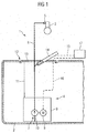
- the pressure sensor is arranged away from the internal combustion engine. Therefore, vibrations of the internal combustion engine are not transmitted to the pressure sensor. Furthermore, high temperatures generated by the internal combustion engine are not transmitted to the pressure sensor thanks to the invention.
- the pressure sensor is therefore charged only with the maximum temperature of 60 ° of the fuel in the flow line. This makes it possible to use a particularly cost-effective pressure sensor.
- the fuel delivery device according to the invention is thus particularly cost-effective.
- a faulty measurement of the pressure sensor by a caused by the fine filter and / or a check valve pressure loss can be easily avoided according to another advantageous embodiment of the invention, when the pressure sensor is located immediately in front of a leading away from the flange connection of the flow line.
Landscapes
- Engineering & Computer Science (AREA)
- Chemical & Material Sciences (AREA)
- Combustion & Propulsion (AREA)
- Mechanical Engineering (AREA)
- General Engineering & Computer Science (AREA)
- Fuel-Injection Apparatus (AREA)
- Cooling, Air Intake And Gas Exhaust, And Fuel Tank Arrangements In Propulsion Units (AREA)
Claims (8)
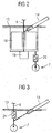
- Dispositif de transport de carburant destiné à alimenter un moteur à combustion interne d'un véhicule automobile en carburant depuis un réservoir de carburant (2), comprenant une pompe à carburant (7) à entraînement électromotorisé disposée dans le réservoir de carburant (2), comprenant une conduite de départ (6) raccordée à la pompe à carburant (7) et destinée à mener au moteur à combustion interne, et comprenant un capteur de pression (14) destiné à déterminer la pression du carburant acheminé au moteur à combustion interne, le capteur de pression (14) étant raccordé à une portion de la conduite de départ (6) qui est éloignée du moteur à combustion interne, caractérisé en ce que le capteur de pression (14) est disposé dans une bride (13) de la pompe à carburant (7) qui ferme une ouverture de montage (12) du réservoir à carburant (2).
- Dispositif de transport de carburant selon la revendication 1, caractérisé en ce que le capteur de pression (14) est raccordé à une portion de la conduite de départ (6) menée à l'intérieur du réservoir à carburant (2).
- Dispositif de transport de carburant selon la revendication 1 ou 2, caractérisé en ce que le capteur de pression (14) est configuré sous la forme d'une unité structurale avec la pompe à carburant (7).
- Dispositif de transport de carburant selon la revendication 1 ou 2, caractérisé en ce qu'un filtre fin (18), le capteur de pression (14), un régulateur de pression (19) et un clapet anti-retour (20, 21) sont réalisés sous la forme d'une unité structurale.
- Dispositif de transport de carburant selon au moins l'une des revendications précédentes, caractérisé en ce que des contacts de raccordement (22) destinés à relier le capteur de pression (14) à une électronique de commande (17) pour une commande en fonction du besoin de la pompe à carburant (7) sont disposés dans une bride (13) qui ferme une ouverture de montage (12) du réservoir à carburant (2).
- Dispositif de transport de carburant selon au moins l'une des revendications précédentes, caractérisé en ce que le capteur de pression (14), vu dans le sens de l'écoulement, est disposé entre la pompe à carburant (7) et le filtre fin (18).
- Dispositif de transport de carburant selon au moins l'une des revendications précédentes, caractérisé en ce que le capteur de pression (14) est disposé directement avant un raccord de la conduite de départ (6) qui s'éloigne de la bride (13).
- Dispositif de transport de carburant selon au moins l'une des revendications précédentes, caractérisé en ce que le capteur de pression (14), vu dans le sens de l'écoulement, est disposé avant le clapet anti-retour (20, 21).
Applications Claiming Priority (2)
| Application Number | Priority Date | Filing Date | Title |
|---|---|---|---|
| DE102006001878A DE102006001878A1 (de) | 2006-01-13 | 2006-01-13 | Kraftstofffördereinrichtung |
| PCT/EP2006/069809 WO2007082616A1 (fr) | 2006-01-13 | 2006-12-18 | Dispositif de transport de carburant |
Publications (2)
| Publication Number | Publication Date |
|---|---|
| EP1977105A1 EP1977105A1 (fr) | 2008-10-08 |
| EP1977105B1 true EP1977105B1 (fr) | 2016-07-06 |
Family
ID=37895975
Family Applications (1)
| Application Number | Title | Priority Date | Filing Date |
|---|---|---|---|
| EP06841404.4A Active EP1977105B1 (fr) | 2006-01-13 | 2006-12-18 | Dispositif de transport de carburant |
Country Status (4)
| Country | Link |
|---|---|
| US (1) | US8065989B2 (fr) |
| EP (1) | EP1977105B1 (fr) |
| DE (1) | DE102006001878A1 (fr) |
| WO (1) | WO2007082616A1 (fr) |
Families Citing this family (2)
| Publication number | Priority date | Publication date | Assignee | Title |
|---|---|---|---|---|
| WO2009067449A1 (fr) * | 2007-11-19 | 2009-05-28 | Robert Bosch Gmbh | Capteur de pression de vapeur et liquide de combustible |
| DE102008044904A1 (de) * | 2008-08-29 | 2010-03-04 | Continental Automotive Gmbh | Kraftstoffversorgungsanlage für ein Kraftfahrzeug |
Family Cites Families (31)
| Publication number | Priority date | Publication date | Assignee | Title |
|---|---|---|---|---|
| US4920942A (en) * | 1987-04-24 | 1990-05-01 | Diesel Kiki Co., Ltd. | Method and apparatus for supplying fuel to internal combustion engines |
| US4926829A (en) * | 1988-11-28 | 1990-05-22 | Walbro Corporation | Pressure-responsive fuel delivery system |
| US4928657A (en) * | 1989-03-02 | 1990-05-29 | Walbro Corporation | In-tank fuel reservoir with fuel level sensor |
| US5044344A (en) * | 1989-10-16 | 1991-09-03 | Walbro Corporation | Pressure-responsive fuel delivery system |
| US5120201A (en) * | 1990-12-17 | 1992-06-09 | Walbro Corporation | Brushless DC fuel pump responsive to pressure sensor |
| US5411002A (en) * | 1991-02-28 | 1995-05-02 | Walter Potoroka, Sr. | Internal combustion engine fuel injection apparatus and system |
| US5261379A (en) * | 1991-10-07 | 1993-11-16 | Ford Motor Company | Evaporative purge monitoring strategy and system |
| US5148792A (en) * | 1992-01-03 | 1992-09-22 | Walbro Corporation | Pressure-responsive fuel delivery system |
| US5267470A (en) * | 1992-04-30 | 1993-12-07 | Siemens Automotive Limited | Pressure sensor mounting for canister purge system |
| FR2695964B1 (fr) * | 1992-09-24 | 1995-07-21 | Walbro Corp | Circuit de distribution de carburant pour moteur a combustion interne. |
| US5351548A (en) * | 1992-12-02 | 1994-10-04 | Walbro Corporation | Capacitive pressure sensor |
| US5361742A (en) * | 1993-02-08 | 1994-11-08 | Walbro Corporation | Fuel pump manifold |
| US5398655A (en) * | 1994-01-14 | 1995-03-21 | Walbro Corporation | Manifold referenced returnless fuel system |
| US5613844A (en) * | 1994-11-15 | 1997-03-25 | Walbro Corporation | Submersible electronic drive module |
| JP3205216B2 (ja) * | 1995-03-30 | 2001-09-04 | 三菱電機株式会社 | 圧力センサ |
| US5961293A (en) * | 1995-05-19 | 1999-10-05 | Uis, Inc | In-take fuel pump assembly with unitary control unit for internal combustion engines |
| JPH08338335A (ja) * | 1995-06-09 | 1996-12-24 | Nippondenso Co Ltd | 内燃機関の燃料供給装置 |
| JP3804814B2 (ja) * | 1996-09-09 | 2006-08-02 | 株式会社デンソー | 内燃機関の燃料供給装置 |
| US6131445A (en) * | 1997-10-10 | 2000-10-17 | Ford Motor Company | Fuel tank sensor assembly |
| DE60016990T2 (de) * | 1999-02-26 | 2005-12-29 | Walbro Corp., Cass City | Fahrzeugbrennstoffsystem |
| IT1308091B1 (it) * | 1999-06-10 | 2001-11-29 | Bitron Spa | Sistema di alimentazione di carburante a pressione controllata perun motore a combustione interna, particolarmente per motoveicoli |
| DE10006622A1 (de) * | 2000-02-15 | 2001-08-16 | Bosch Gmbh Robert | Kraftstoffversorgungseinrichtung für eine Brennkraftmaschine eines Kraftfahrzeugs |
| US6877488B2 (en) * | 2002-05-29 | 2005-04-12 | Nartron Corporation | Vehicle fuel management system |
| JP2004124817A (ja) * | 2002-10-02 | 2004-04-22 | Mitsubishi Electric Corp | 燃料ポンプモジュールおよび車両用の燃料タンク内圧センサ |
| JP2004218571A (ja) * | 2003-01-16 | 2004-08-05 | Aisan Ind Co Ltd | エンジンの燃料供給装置 |
| DE10355804A1 (de) | 2003-11-28 | 2005-06-30 | Robert Bosch Gmbh | Vorrichtung zum Fördern von Kraftstoff aus einem Vorratsbehälter zu einer Brennkraftmaschine und Verfahren zur Druckerfassung |
| JP2005201068A (ja) * | 2004-01-13 | 2005-07-28 | Denso Corp | 燃料判別装置 |
| JP4261412B2 (ja) * | 2004-04-16 | 2009-04-30 | 株式会社日立製作所 | 内燃機関の燃料供給装置 |
| JP2007231907A (ja) * | 2006-03-03 | 2007-09-13 | Denso Corp | 燃料供給装置 |
| JP4415277B2 (ja) * | 2006-04-20 | 2010-02-17 | 株式会社デンソー | 燃料供給装置 |
| WO2009067449A1 (fr) * | 2007-11-19 | 2009-05-28 | Robert Bosch Gmbh | Capteur de pression de vapeur et liquide de combustible |
-
2006
- 2006-01-13 DE DE102006001878A patent/DE102006001878A1/de not_active Ceased
- 2006-12-18 EP EP06841404.4A patent/EP1977105B1/fr active Active
- 2006-12-18 WO PCT/EP2006/069809 patent/WO2007082616A1/fr not_active Ceased
- 2006-12-18 US US12/160,653 patent/US8065989B2/en not_active Expired - Fee Related
Also Published As
| Publication number | Publication date |
|---|---|
| DE102006001878A1 (de) | 2007-07-19 |
| WO2007082616A1 (fr) | 2007-07-26 |
| EP1977105A1 (fr) | 2008-10-08 |
| US20100154751A1 (en) | 2010-06-24 |
| US8065989B2 (en) | 2011-11-29 |
Similar Documents
| Publication | Publication Date | Title |
|---|---|---|
| EP0357882B1 (fr) | Dispositif pour alimenter le tuyau d'admission d'un moteur à combustion interne en quantités dosées de composants volatils de carburants | |
| DE102014219926A1 (de) | Elektronische drossel | |
| EP1435458A1 (fr) | Unité de pompe de dosage | |
| WO2005024196B1 (fr) | Dispositif de traitement postérieur de gaz d'échappement pour des moteurs diesel de véhicules à moteur, en particulier d'automobiles | |
| DE102008060033A1 (de) | Temperaturfühler für Turbolader | |
| DE102011118711A1 (de) | Messvorrichtung | |
| DE112015002023T5 (de) | Sensorplatte für ein Einzeleinheit-Nachbehandlungssystem | |
| DE102014102596A1 (de) | Blowby-Einrichtung | |
| DE202016004870U1 (de) | Sensoranordnung zum Einbau in einen Fluidtank eines Abgasnachbehandlungssystems | |
| DE19837954C1 (de) | Fördereinheit | |
| EP1977105B1 (fr) | Dispositif de transport de carburant | |
| DE112017002822T5 (de) | Integrierte Vorrichtung, Abgasnachbehandlungssystem und Steuerungsverfahren | |
| DE102012221697B4 (de) | Motorsteuereinheit | |
| EP2159407B1 (fr) | Installation d'alimentation en carburant pour un véhicule automobile | |
| EP1481156B1 (fr) | Unite d'acheminement de carburant | |
| WO2019002157A1 (fr) | Système de réservoir pour un additif | |
| DE112019002312T5 (de) | Vorrichtung zur detektion einer physikalischen grösse | |
| EP2612121B1 (fr) | Capteur combiné | |
| DE102017006080A1 (de) | Fördermodul zur Anbringung an einem Tank | |
| EP1260686B1 (fr) | Dispositif de détection de température pour un moteur à combustion interne | |
| DE102022208864A1 (de) | Sensor, Kanal und Brennstoffzellensystem | |
| DE19841657C1 (de) | Anordnung mit einem Drucksensor für eine Brennkraftmaschine | |
| DE102012221866A1 (de) | Anordnung zur Nachbehandlung des Abgases einer Brennkraftmaschine | |
| WO2011110447A1 (fr) | Agencement d'un appareil de commande de moteur sur un moteur à combustion interne et système de moteur | |
| DE102013011409A1 (de) | Baukastensystem für eine Mehrzahl von Bauvaraianten einer Kraftstofffördereinrichtung einer Verbrennungskraftmaschine |
Legal Events
| Date | Code | Title | Description |
|---|---|---|---|
| PUAI | Public reference made under article 153(3) epc to a published international application that has entered the european phase |
Free format text: ORIGINAL CODE: 0009012 |
|
| 17P | Request for examination filed |
Effective date: 20080813 |
|
| AK | Designated contracting states |
Kind code of ref document: A1 Designated state(s): DE ES FR GB IT |
|
| DAX | Request for extension of the european patent (deleted) | ||
| RBV | Designated contracting states (corrected) |
Designated state(s): DE ES FR GB IT |
|
| 17Q | First examination report despatched |
Effective date: 20111215 |
|
| GRAP | Despatch of communication of intention to grant a patent |
Free format text: ORIGINAL CODE: EPIDOSNIGR1 |
|
| INTG | Intention to grant announced |
Effective date: 20160105 |
|
| GRAS | Grant fee paid |
Free format text: ORIGINAL CODE: EPIDOSNIGR3 |
|
| GRAA | (expected) grant |
Free format text: ORIGINAL CODE: 0009210 |
|
| AK | Designated contracting states |
Kind code of ref document: B1 Designated state(s): DE ES FR GB IT |
|
| REG | Reference to a national code |
Ref country code: GB Ref legal event code: FG4D Free format text: NOT ENGLISH |
|
| REG | Reference to a national code |
Ref country code: DE Ref legal event code: R096 Ref document number: 502006015033 Country of ref document: DE |
|
| REG | Reference to a national code |
Ref country code: FR Ref legal event code: PLFP Year of fee payment: 11 |
|
| PG25 | Lapsed in a contracting state [announced via postgrant information from national office to epo] |
Ref country code: ES Free format text: LAPSE BECAUSE OF FAILURE TO SUBMIT A TRANSLATION OF THE DESCRIPTION OR TO PAY THE FEE WITHIN THE PRESCRIBED TIME-LIMIT Effective date: 20160706 |
|
| REG | Reference to a national code |
Ref country code: DE Ref legal event code: R097 Ref document number: 502006015033 Country of ref document: DE |
|
| PLBE | No opposition filed within time limit |
Free format text: ORIGINAL CODE: 0009261 |
|
| STAA | Information on the status of an ep patent application or granted ep patent |
Free format text: STATUS: NO OPPOSITION FILED WITHIN TIME LIMIT |
|
| 26N | No opposition filed |
Effective date: 20170407 |
|
| GBPC | Gb: european patent ceased through non-payment of renewal fee |
Effective date: 20161218 |
|
| PG25 | Lapsed in a contracting state [announced via postgrant information from national office to epo] |
Ref country code: GB Free format text: LAPSE BECAUSE OF NON-PAYMENT OF DUE FEES Effective date: 20161218 |
|
| REG | Reference to a national code |
Ref country code: FR Ref legal event code: PLFP Year of fee payment: 12 |
|
| PGFP | Annual fee paid to national office [announced via postgrant information from national office to epo] |
Ref country code: IT Payment date: 20191230 Year of fee payment: 14 |
|
| REG | Reference to a national code |
Ref country code: DE Ref legal event code: R081 Ref document number: 502006015033 Country of ref document: DE Owner name: VITESCO TECHNOLOGIES GMBH, DE Free format text: FORMER OWNER: CONTINENTAL AUTOMOTIVE GMBH, 30165 HANNOVER, DE |
|
| PG25 | Lapsed in a contracting state [announced via postgrant information from national office to epo] |
Ref country code: IT Free format text: LAPSE BECAUSE OF NON-PAYMENT OF DUE FEES Effective date: 20201218 |
|
| REG | Reference to a national code |
Ref country code: DE Ref legal event code: R081 Ref document number: 502006015033 Country of ref document: DE Owner name: SCHAEFFLER TECHNOLOGIES AG & CO. KG, DE Free format text: FORMER OWNER: VITESCO TECHNOLOGIES GMBH, 30165 HANNOVER, DE Ref country code: DE Ref legal event code: R081 Ref document number: 502006015033 Country of ref document: DE Owner name: VITESCO TECHNOLOGIES GMBH, DE Free format text: FORMER OWNER: VITESCO TECHNOLOGIES GMBH, 30165 HANNOVER, DE |
|
| REG | Reference to a national code |
Ref country code: DE Ref legal event code: R084 Ref document number: 502006015033 Country of ref document: DE |
|
| P01 | Opt-out of the competence of the unified patent court (upc) registered |
Effective date: 20230530 |
|
| REG | Reference to a national code |
Ref country code: DE Ref legal event code: R081 Ref document number: 502006015033 Country of ref document: DE Owner name: SCHAEFFLER TECHNOLOGIES AG & CO. KG, DE Free format text: FORMER OWNER: VITESCO TECHNOLOGIES GMBH, 93055 REGENSBURG, DE |
|
| PGFP | Annual fee paid to national office [announced via postgrant information from national office to epo] |
Ref country code: FR Payment date: 20251222 Year of fee payment: 20 |
|
| PGFP | Annual fee paid to national office [announced via postgrant information from national office to epo] |
Ref country code: DE Payment date: 20251231 Year of fee payment: 20 |