EP1977112B1 - Centrifugal pump having an axial thrust balancing device - Google Patents
Centrifugal pump having an axial thrust balancing device Download PDFInfo
- Publication number
- EP1977112B1 EP1977112B1 EP07711923A EP07711923A EP1977112B1 EP 1977112 B1 EP1977112 B1 EP 1977112B1 EP 07711923 A EP07711923 A EP 07711923A EP 07711923 A EP07711923 A EP 07711923A EP 1977112 B1 EP1977112 B1 EP 1977112B1
- Authority
- EP
- European Patent Office
- Prior art keywords
- pressure
- centrifugal pump
- impeller
- axial
- bearing
- Prior art date
- Legal status (The legal status is an assumption and is not a legal conclusion. Google has not performed a legal analysis and makes no representation as to the accuracy of the status listed.)
- Active
Links
Images

Classifications
-
- F—MECHANICAL ENGINEERING; LIGHTING; HEATING; WEAPONS; BLASTING
- F04—POSITIVE - DISPLACEMENT MACHINES FOR LIQUIDS; PUMPS FOR LIQUIDS OR ELASTIC FLUIDS
- F04D—NON-POSITIVE-DISPLACEMENT PUMPS
- F04D29/00—Details, component parts, or accessories
- F04D29/08—Sealings
- F04D29/16—Sealings between pressure and suction sides
- F04D29/165—Sealings between pressure and suction sides especially adapted for liquid pumps
- F04D29/167—Sealings between pressure and suction sides especially adapted for liquid pumps of a centrifugal flow wheel
-
- F—MECHANICAL ENGINEERING; LIGHTING; HEATING; WEAPONS; BLASTING
- F04—POSITIVE - DISPLACEMENT MACHINES FOR LIQUIDS; PUMPS FOR LIQUIDS OR ELASTIC FLUIDS
- F04D—NON-POSITIVE-DISPLACEMENT PUMPS
- F04D29/00—Details, component parts, or accessories
- F04D29/04—Shafts or bearings, or assemblies thereof
- F04D29/041—Axial thrust balancing
- F04D29/0413—Axial thrust balancing hydrostatic; hydrodynamic thrust bearings
-
- F—MECHANICAL ENGINEERING; LIGHTING; HEATING; WEAPONS; BLASTING
- F04—POSITIVE - DISPLACEMENT MACHINES FOR LIQUIDS; PUMPS FOR LIQUIDS OR ELASTIC FLUIDS
- F04D—NON-POSITIVE-DISPLACEMENT PUMPS
- F04D29/00—Details, component parts, or accessories
- F04D29/04—Shafts or bearings, or assemblies thereof
- F04D29/041—Axial thrust balancing
- F04D29/0416—Axial thrust balancing balancing pistons
Definitions
- the invention relates to a single-stage centrifugal pump with Axialschubaus stressess founded, wherein in the housing of the centrifugal pump connected to a shaft impeller is rotating, at least one arranged between impeller and housing split ring seal forms a discharge space, the discharge space is connected to a pressure-transmitting connection to the pressure range of the centrifugal pump, and between shaft and housing a shaft seal is arranged.
- a generic Axialschubentlastungs is through the DE 196 31 824 A1 known.
- a first radially flowed regulating gap between the impeller outlet and a suction-side radial bearing is arranged in the suction-side impeller region.
- Such a suction-side shaft bearing is designed as a sliding bearing, arranged directly on the Laufradsaugmund and consuming to produce.
- a second radially flowed control gap is arranged in the pressure-side impeller region with respect to the first control gap on a smaller diameter.
- a control device for an axial thrust compensation of a hydrostatic thrust bearing assembly in which the change in the carrying capacity is achieved with a hydrostatic device.
- a shaft driving the impeller is held radially in a bearing carrier in two cylinder bearings and additionally axially positioned in two disc-shaped thrust bearings.
- a continuously pumping device generates in the thrust bearings a hydrostatic bearing pressure which can vary depending on the gap width of the bearing.
- Axial shifts of the shaft lead to such changes in the gap width and influence the hydrodynamic bearing pressures in the two thrust bearings.
- a pressure difference between the two bearings serves as a control variable for a control valve of an axial thrust balancing device of the impeller. It has a complex structure for special Special cases is justified.
- the disadvantage here is the risk of environmental hazards due to the complex lubricant lines, as they can leak or be damaged.
- the DD 231 829 A1 shows in a centrifugal pump another method to compensate for an axial thrust.
- a compensating piston rotating with the shaft is arranged in an additional housing part, the diameter of which corresponds approximately to half the impeller diameter.
- a long throttle section is formed, whereby, seen in the flow direction, form different pressure regions in front of and behind the balance piston.
- two pressure measuring points which measure the pump pressure in the discharge nozzle and in the space behind the balance piston, a pressure difference that can be determined from this is transmitted to a computer.
- the signal of a speed measuring device is fed into the computer.
- the calculator determines a discharge pressure for the space behind the balance piston at a difference occurring between axial thrust and balancing force of the balance piston. And by a control signal to a control valve, the pressure in the area behind the balance piston is changed so far until a state of equilibrium and thus relief of the shaft bearing occurs.
- the disadvantage is the detection and processing of three parameters and the use of a special balance piston, which does not contribute directly to the function of the pump, increases the overall volume and variety of parts and increases the susceptibility to failure.
- the invention is therefore based on the object to achieve a less complex and reliable reduction of the axial thrust, which ensures a high bearing life and a long life of the shaft seal for a roller bearing pump shaft.
- the solution provides that the shaft is provided in a conventional manner with at least one thrust bearing receiving axial forces and that via a connection, a pressure difference between a pressure in the discharge chamber and a body other pressure in the centrifugal pump housing as a direction constant and permissible axial force presses the rotating pump parts against the rolling bearing.
- This ensures a continuous and defined load for the bearings and also for the shaft seal.
- the cause of damage to bearings and shaft seals is a problem of known balancing devices at certain operating points to achieve only an insufficient reduction of the axial force or to avoid a pendulum of the axial force by the value 0 can.
- the conditional in the latter case sign change of such a small axial force leads to the so-called swimming of the rotating parts. This turns out to be their alternating axial movement with appreciable frequency between the stops of the axial bearing.
- Such minimal oscillating movements have in addition to the damage to the bearings and the shaft seals also an adverse noise result and are inventively avoided.
- the dimensions of the split-ring seals, the shaft seal chamber and the relief chamber are selected in order to achieve a defined axial thrust on the force-absorbing rolling bearing via the connection and the different pressures.
- the acting axial force is smaller than the permissible bearing load of the force-absorbing rolling bearing, whereby the bearing life is extended.
- a throttling device arranged in the connection sets in the discharge chamber the direction-constant axial force arising from the pressure difference on the roller bearing.
- the throttle device is designed as a permanently adjustable throttle device.
- the direction constant axial force generated on the bearings is by a arranged in the connection, adjustable or controllable throttle device in the discharge space.
- Their size is chosen so that it always lies well below the permissible axial bearing force in order not to adversely affect the bearing life. And their size is chosen so large that a self-adjusting axial force prevents floating of the rotating parts and thus their premature destruction reliable.
- a variable via the connection in its pressure relief space on the suction side or the pressure side of the impeller is arranged.
- only one relief space is changed in its pressure via the pressure-transmitting connection, in order to obtain a defined axial force on the rolling bearing.
- the connection can be made between the suction side or the pressure side of the pump. This depends on the dimensions inside the pump housing and those of the impeller.
- a sensor detects an axial roller bearing load
- a controller generates with the sensor signal an actuating signal for an adjustable throttle device and the throttle device sets in the discharge space a rolling bearing loading axial force.
- the senor detects the axial bearing load according to size and direction.
- one or more controller characteristic (s) stored in the controller corrects or corrects influences that alter the axial bearing load.
- the controller processes these signal values and restores the permissible operating status with the help of one or several controller characteristic (s).
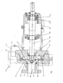
- Fig. 1 shows the impeller 2 has in the region of the impeller inlet via a suction-side throttle gap in the form of a gap seal 4, which ensures a high pressure in the suction side impeller side space 5 and reduces gap losses.
- the impeller 2 on a larger diameter on a second, here pressure-side gap seal 6, which ensures a high pressure in the larger side diameter impeller side space 7 in the larger diameter range.
- the pressure-side gap seal 6 bounded or enveloped with its diameter a arranged on a smaller diameter discharge chamber 8, which is connected via a connection 13 with an adjustable throttle device 14 disposed therein with a location other pressure, here the discharge nozzle 15 of the centrifugal pump.
- the connection 13 may be designed as a conventional conduit system.
- the in Fig. 1 selected location other pressure has a higher pressure than that of the discharge chamber 8 and the choice of location is dependent on the subsequent operating conditions of a pump.
- the location of other pressure may be in the area of the impeller outlet, a guide, the discharge nozzle or the location is as an external Pressure reservoir formed.
- the pressure level on the impeller back or in the impeller side impeller range is set to a value. From the area ratios in the suction-side impeller side space 5, in the pressure-side impeller side space 7 and in the relief space 8 as well as the pressures in these spaces, different forces result. Another force results from the pressure in the suction port 18 in conjunction with a shaft seal 17 in the space 16, since the latter seals against atmospheric pressure from the pressure loads on the impeller 2 results in a defined axial force F A, the impeller 2 and the driving shaft 10 in the direction of Rolling 11 to 11.2 pushes.
- the rolling bearing 11 is formed in the embodiment shown as a pure radial bearing, while two paired bearings 11.1 and 11.2 record the radial and axial forces due to their training. They consist of two angular contact ball bearings, whereby other types of rolling bearings are applicable.
- the shaft 10 which is mounted here in a bearing carrier 12, may also be formed with elimination of the bearing carrier as part of a driving electric motor.
- the bearings of the motor are dimensioned accordingly to accommodate an axial thrust of the pump can.
- the appropriately designed bearing support 12 or the pump cover 3 can be provided with a - known per se, not shown here - short stub shaft, which would be held only in a rolling bearing 11.1. Their shaft end would then be connected to a stub shaft of a block motor.
- the pressure level in the discharge chamber 8 is set during operation over a wide range of values.
- relief holes 9 on the impeller 2 is no longer necessary and available.
- the pressure in the relief chamber 8 and a shaft seal chamber 16 is adjusted so that a resulting axial force F A is formed as a fixed bearing shaft bearing in the form of rolling bearings 11.1, 11.2 always below their allowable limits.
- a resulting axial force F A is formed as a fixed bearing shaft bearing in the form of rolling bearings 11.1, 11.2 always below their allowable limits.
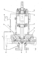
- Fig. 2 corresponds in structure to the illustration in Fig. 1 However, wherein the pressure-side discharge chamber 8 via the connection 13 with the suction side 18 of the centrifugal pump is in operative connection. Also in this case, the impeller 2 is equipped with no relief holes. Instead, the pressure level in the discharge chamber 8 and shaft seal chamber 16 is adjusted by means of the adjustable throttle device 14.1 so that the load on the shaft seal 17 and the rolling bearing 11.1, 11.2 always below the allowable bearings Limits are.
- a sensor 19 which is connected to a controller 20 is used. Changes in the storage condition are detected by the sensor 19 and passed on to the controller 20 on. This determines a controller signal, with the aid of which the controllable throttle device 14.1 adjusted and the permissible axial force F A is set again.
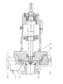
- Fig. 3 shows a variant in which a suction-side relief space 21 is formed by a second, arranged on a larger diameter, suction-side throttle gap in the form of a gap seal 22 with a gap diameter D and a gap width s.
- the in the Fig. 1 and 2 represented pressure-side relief space is omitted in this variant.
- This suction-side relief chamber 21 is connected via the connection 13 with integrated throttle device 14 with the pressure range from the discharge nozzle 15 connected to the centrifugal pump. By appropriate adjustment of the throttle device 14, the generation of the continuous axial force F A is ensured.
- Fig. 4 shows a variant of Fig. 3 , wherein the centrifugal pump is designed for operation with a very high inlet pressure.
- the suction-side relief space 21 is connected to the suction region 18 via the pressure-carrying connection 13 in order to ensure the defined axial force F A on the shaft bearing 11.1, 11.2.
- the axial force F A can be influenced.
- the axial forces receiving bearing which consists of two bearings 11.1, 11.2 in the form of angular contact ball bearings, arranged a bearing load sensor, which continuously determines the axial force. He may as well in the embodiments of the Fig. 1 and 3 Find use. It provides a signal to a control device 20, which compares a respective existing axial force F A with a stored setpoint. In the event of a deviation, the control device 20 generates a control signal for an adjustable throttle device 14.1. This regulates the pressure in the relief chamber 8 or 21 to a value which has a defined, low axial force F A for the rolling bearings 11.1, 11.2 result.
Landscapes
- Engineering & Computer Science (AREA)
- Mechanical Engineering (AREA)
- General Engineering & Computer Science (AREA)
- Physics & Mathematics (AREA)
- Fluid Mechanics (AREA)
- Control Of Non-Positive-Displacement Pumps (AREA)
- Structures Of Non-Positive Displacement Pumps (AREA)
Description
Die Erfindung betrifft eine einstufige Kreiselpumpe mit Axialschubausgleichseinrichtung, wobei im Gehäuse der Kreiselpumpe ein mit einer Welle verbundenes Laufrad rotierend angeordnet ist, mindestens eine zwischen Laufrad und Gehäuse angeordnete Spaltringabdichtung einen Entlastungsraum bildet, der Entlastungsraum mit einer druckübertragenden Verbindung an den Druckbereich der Kreiselpumpe angeschlossen ist, und zwischen Welle und Gehäuse eine Wellenabdichtung angeordnet ist.The invention relates to a single-stage centrifugal pump with Axialschubausgleichseinrichtung, wherein in the housing of the centrifugal pump connected to a shaft impeller is rotating, at least one arranged between impeller and housing split ring seal forms a discharge space, the discharge space is connected to a pressure-transmitting connection to the pressure range of the centrifugal pump, and between shaft and housing a shaft seal is arranged.
Das Prinzip einer Axialschubentlastung ist im
Die Druckschrift
Eine gattungsgemäße Axialschubentlastungseinrichtung ist durch die
Weiter ist im druckseitigen Laufradbereich gegenüber dem ersten Regelspalt auf kleinerem Durchmesser ein zweiter radial durchströmter Regelspalt angeordnet. Mit dieser Regelspalten-Lösung ist ein vollständiger Ausgleich des vom Laufrad erzeugten hydraulischen Axialschubes und in axialer Richtung ein berührungsfreier Betrieb des Laufrades möglich. Ein zusätzliches Axiallager ist für den normalen Betriebszustand nicht mehr erforderlich. Allenfalls für kurzzeitig zu durchfahrende Betriebszustände während einer Anfahr- oder Auslaufphase einer Pumpe sind sicherheitshalber die Regelspalte begrenzenden Flächen als Axiallagerflächen ausgebildet.Next, a second radially flowed control gap is arranged in the pressure-side impeller region with respect to the first control gap on a smaller diameter. With this control column solution, a complete compensation of the hydraulic axial thrust generated by the impeller and in the axial direction a non-contact operation of the impeller is possible. An additional thrust bearing is no longer required for the normal operating condition. At best, for briefly to be traversed operating conditions during a start-up or discharge phase of a pump, the rule column limiting surfaces are designed as thrust bearing surfaces for safety's sake.
Eine andere Einrichtung zum Axialsühubausgleich für ein- oder mehrstufige Kreiselpumpen mit geschlossenen Laufrädern ist durch die
Durch die
Und die
Der Erfindung liegt daher die Aufgabe zugrunde, eine wenig aufwendige und betriebssichere Reduzierung des Axialschubs zu erreichen, die für eine wälzgelagerte Pumpenwelle eine hohe Lagerlebensdauer sowie eine hohe Lebensdauer der Wellenabdichtung gewährleistet.The invention is therefore based on the object to achieve a less complex and reliable reduction of the axial thrust, which ensures a high bearing life and a long life of the shaft seal for a roller bearing pump shaft.
Die Lösung sieht vor, dass die Welle in an sich bekannter Weise mit mindestens einem Axialkräfte aufnehmenden Wälzlager versehen ist und dass über eine Verbindung eine Druckdifferenz zwischen einem Druck im Entlastungsraum und einer Stelle anderen Druckes im Kreiselpumpengehäuse als eine richtungskonstante und zulässige Axialkraft die rotierenden Pumpenteile gegen das Wälzlager presst. Damit ist für die Lager und auch auf die Wellendichtung eine kontinuierliche und definierte Belastung gewährleistet. Es wurde erkannt, ursächlich für Schäden an Lagern und Wellenabdichtungen ist ein Problem von bekannten Ausgleichseinrichtungen bei bestimmten Betriebspunkten nur eine unzureichende Reduzierung der Axialkraft zu erreichen oder auch ein Pendeln der Axialkraft um den Wert 0 nicht vermeiden zu können. Der im letztgenannten Fall bedingte Vorzeichenwechsel einer solchen geringen Axialkraft führt zum sogenannten Schwimmen der rotierenden Teile. Dies stellt sich als deren wechselnde axiale Bewegung mit nennenswerter Frequenz zwischen den Anschlägen der Axiallagerung dar. Solche minimalen oszillierenden Bewegungen haben neben den Beschädigungen der Lager und der Wellenabdichtungen auch eine nachteilige Geräuschentwicklung zur Folge und werden erfindungsgemäß vermieden.The solution provides that the shaft is provided in a conventional manner with at least one thrust bearing receiving axial forces and that via a connection, a pressure difference between a pressure in the discharge chamber and a body other pressure in the centrifugal pump housing as a direction constant and permissible axial force presses the rotating pump parts against the rolling bearing. This ensures a continuous and defined load for the bearings and also for the shaft seal. It has been recognized that the cause of damage to bearings and shaft seals is a problem of known balancing devices at certain operating points to achieve only an insufficient reduction of the axial force or to avoid a pendulum of the axial force by the value 0 can. The conditional in the latter case sign change of such a small axial force leads to the so-called swimming of the rotating parts. This turns out to be their alternating axial movement with appreciable frequency between the stops of the axial bearing. Such minimal oscillating movements have in addition to the damage to the bearings and the shaft seals also an adverse noise result and are inventively avoided.
Da für die Auslegung einer Kreiselpumpe die jeweiligen Betriebsbedingungen bekannt sind, werden die Abmessungen der Spaltringabdichtungen, des Wellendichtungsraums und für den Entlastungsraum entsprechend ausgewählt, um über die Verbindung und die unterschiedlichen Drücke einen definierten Axialschub auf das Kräfte aufnehmende Wälzlager zu erreichen. Dabei ist nach einer Ausgestaltung die einwirkende Axialkraft kleiner als die zulässige Lagerbelastung des kräfteaufnehmenden Wälzlagers, wodurch die Lagerlebensdauer verlängert wird.Since the respective operating conditions are known for the design of a centrifugal pump, the dimensions of the split-ring seals, the shaft seal chamber and the relief chamber are selected in order to achieve a defined axial thrust on the force-absorbing rolling bearing via the connection and the different pressures. In this case, according to one embodiment, the acting axial force is smaller than the permissible bearing load of the force-absorbing rolling bearing, whereby the bearing life is extended.
Nach weiteren Ausgestaltungen stellt eine in der Verbindung angeordnete Drosseleinrichtung im Entlastungsraum die aus der Druckdifferenz entstehende richtungskonstante Axialkraft auf das Wälzlager ein. Für einen Kreiselpumpenbetrieb mit annähernd konstanten Betriebsparametern ist es eine feste oder einstellbare Drosseleinrichtung. Für Betriebszustände, bei denen die Varianz der Betriebsparameter sehr gering ist oder die eine Adaption an veränderte Betriebsparameter nicht erfordern, ist die Drosseleinrichtung als eine fest einstellbare Drosseleinrichtung ausgebildet. Und für Einsatzfälle mit veränderlichen Betriebsparametern einer Kreiselpumpe wird durch eine in der Verbindung angeordnete, einstell- oder regelbare Drosseleinrichtung in dem Entlastungsraum die richtungskonstante Axialkraft auf das Wälzlager erzeugt. Dadurch wird immer eine geringe und in ihrer Richtung unveränderliche Axialkraft beibehalten. Deren Größe wird so gewählt, dass sie immer wesentlich unterhalb der zulässigen Axiallagerkraft liegt, um die Lagerlebensdauer nicht negativ zu beeinträchtigen. Und ihre Größe wird so groß gewählt, dass eine sich einstellende Axialkraft ein Schwimmen der rotierenden Teile und damit deren vorzeitige Zerstörung zuverlässig verhindert.According to further embodiments, a throttling device arranged in the connection sets in the discharge chamber the direction-constant axial force arising from the pressure difference on the roller bearing. For a centrifugal pump operation with approximately constant operating parameters, it is a fixed or adjustable throttle device. For operating states in which the variance of the operating parameters is very low or which do not require an adaptation to changed operating parameters, the throttle device is designed as a permanently adjustable throttle device. And for applications with variable operating parameters of a centrifugal pump is by a arranged in the connection, adjustable or controllable throttle device in the discharge space, the direction constant axial force generated on the bearings. As a result, a low and constant in their direction axial force is always maintained. Their size is chosen so that it always lies well below the permissible axial bearing force in order not to adversely affect the bearing life. And their size is chosen so large that a self-adjusting axial force prevents floating of the rotating parts and thus their premature destruction reliable.
Nach einer weiteren Ausgestaltung ist ein über die Verbindung in seinem Druck veränderbarer Entlastungsraum auf der Saugseite oder der Druckseite des Laufrades angeordnet. Somit wird über die druckübertragende Verbindung immer nur ein Entlastungsraum in seinem Druck verändert, um eine definierte Axialkraft auf das Wälzlager zu erhalten. Die Verbindung kann dabei zwischen der Saugseite oder der Druckseite der Pumpe hergestellt werden. Dies ist abhängig von den Abmessungen innerhalb des Pumpengehäuses und von denen des Laufrades.According to a further embodiment, a variable via the connection in its pressure relief space on the suction side or the pressure side of the impeller is arranged. Thus, only one relief space is changed in its pressure via the pressure-transmitting connection, in order to obtain a defined axial force on the rolling bearing. The connection can be made between the suction side or the pressure side of the pump. This depends on the dimensions inside the pump housing and those of the impeller.
Nach einer weiteren Ausgestaltung erfasst ein Sensor eine axiale Wälzlagerbelastung, ein Regler erzeugt mit dem Sensorsignal ein Stellsignal für eine verstellbare Drosseleinrichtung und die Drosseleinrichtung stellt im Entlastungsraum eine das Wälzlager belastende Axialkraft ein. Dies hat den zusätzlichen Vorteil der Unabhängigkeit der Regelung vom Verschleißverhalten der flüssigkeitsberührten Teile. Eine Größenveränderung in einem der Laufrad-Drosselspalte würde andere Druckverhältnisse in dem Entlastungsraum und damit andere Kräfte auf das Wälzlager bedingen. Solche sich während einer längeren Betriebsdauer allmählich einstellende Veränderungen werden aber durch den Sensor sofort erfasst und vom Regler in Form eines angepassten Reglersignals kompensiert.According to a further embodiment, a sensor detects an axial roller bearing load, a controller generates with the sensor signal an actuating signal for an adjustable throttle device and the throttle device sets in the discharge space a rolling bearing loading axial force. This has the additional advantage of independence of the control of the wear behavior of the wetted parts. A change in size in one of the impeller throttle gaps would cause different pressure conditions in the relief space and thus other forces on the rolling bearing. However, such gradually occurring changes during a longer period of operation are detected by the sensor immediately and compensated by the controller in the form of an adapted control signal.
Hierbei erfasst der Sensor die axiale Lagerbelastung nach Größe und Richtung. Dazu sieht eine Weiterung vor, dass eine oder mehrere im Regler hinterlegte Reglerkennlinie(n) die axiale Lagerbelastung verändernde Einflüsse korrigiert oder korrigieren. Mit Hilfe des Sensorsignals werden im Bereich des Lagers auftretende Instabilitäten, Axialkräfte und/oder Drücke in einem Entlastungs- und/oder Wellendichtungsraum erfasst. Der Regler verarbeitet diese Signalwerte und stellt mit Hilfe einer oder verschiedener Reglerkennlinie(n) den zulässigen Betriebszustand wieder her. Somit wird auch bei unkalkulierbaren Betriebssituationen, die durch überraschende äußere Einflüsse bedingt sind, zuverlässig eine Überlastung und damit eine Schädigung der Lager und der Wellendichtung verhindert.In this case, the sensor detects the axial bearing load according to size and direction. For this purpose, a further provision provides that one or more controller characteristic (s) stored in the controller corrects or corrects influences that alter the axial bearing load. With the aid of the sensor signal, instabilities, axial forces and / or pressures occurring in the region of the bearing are detected in a relief and / or shaft seal chamber. The controller processes these signal values and restores the permissible operating status with the help of one or several controller characteristic (s). Thus, even with incalculable operating situations, which are caused by surprising external influences, reliably prevents overloading and thus damage to the bearings and the shaft seal.
Ausführungsbeispiele der Erfindung sind in den Zeichnungen dargestellt und werden im folgenden näher beschrieben. Es zeigen die
- Fig. 1 - 4
- verschiedene Ausbildungen eines Entlastungsraumes am Laufrad einer einstufigen Kreiselpumpe.
- Fig. 1 - 4th
- various embodiments of a discharge chamber on the impeller of a single-stage centrifugal pump.
Durch die Wahl des Spaltdurchmessers D der druckseitigen Spaltdichtung 6, deren Spaltweite S und mit Hilfe der Verbindung 13 mit Drossel 14 wird das Druckniveau auf der Laufradrückseite oder im druckseitigen Laufradbereich auf einen Wert eingestellt. Aus den Flächenverhältnissen im saugseitigen Laufradseitenraum 5, im druckseitigen Laufradseitenraum 7 und im Entlastungsraum 8 sowie der Drücke in diesen Räumen resultieren unterschiedliche Kräfte. Eine weitere Kraft resultiert aus dem Druck im Saugstutzen 18 in Verbindung mit einer Wellendichtung 17 im Raum 16, da letztere gegen Atmosphärendruck abdichtet Aus den Druckbelastungen auf das Laufrad 2 resultiert eine definierte Axialkraft FA die das Laufrad 2 und die antreibende Welle 10 in Richtung der Wälzlager 11 bis 11.2 schiebt. Von den im Lagerträger 12 angeordneten Wälzlagern ist das Wälzlager 11 in der gezeigten Ausführungsform als ein reines Radiallager ausgebildet, während zwei paarweise angeordnete Wälzlager 11.1 und 11.2 aufgrund ihrer Ausbildung die Radial- und Axialkräfte aufnehmen. Sie bestehen hier aus zwei Schrägkugellagern, wobei auch andere Wälzlagerbauformen anwendbar sind.By choosing the gap diameter D of the pressure-side gap seal 6, the gap width S and with the aid of the
Und die Welle 10, die hier in einem Lagerträger 12 gelagert ist, kann ebenso gut unter Wegfall des Lagerträger als ein Bestandteil eines antreibenden Elektromotors ausgebildet sein. In einem solchen Fall sind die Wälzlager des Motors entsprechend dimensioniert, um einen Axialschub der Pumpe aufnehmen zu können. Ist dieses nicht der Fall, kann der entsprechend ausgebildete Lagerträger 12 oder der Pumpendeckel 3 mit einer - an sich bekannten, hier nicht dargestellten - kurzen Steckwelle versehen sein, die nur in einem Wälzlager 11.1 gehalten wäre. Deren Wellenende würde dann mit einem Wellenstumpf eines Blockmotors verbunden werden.And the
Mit Hilfe der einstellbaren Drosseleinrichtung 14 wird das Druckniveau im Entlastungsraum 8 während des Betriebes über einen großen Wertebereich eingestellt. Bei Verwendung einer Drosseleinrichtung 14 sind bisher übliche, hier gestrichelt dargestellte Entlastungsbohrungen 9 am Laufrad 2 nicht mehr erforderlich und vorhanden. Der Druck im Entlastungsraum 8 und einem Wellendichtungsraum 16 wird so eingestellt, dass eine daraus resultierende Axialkraft FA das als Festlager ausgebildete Wellenlager in Form der Wälzlager 11.1, 11.2 immer unterhalb von deren zulässigen Grenzwerten liegt. Sollten sich während der Lebensdauer einer Pumpe durch einen Verschleiß in der Spaltdichtung 4 der 6 andere Druckverhältnisse im Raum 5 und/oder 8 einstellen oder Schwingungen der rotierenden Teile auftreten, so kann durch einfaches Verstellen der Drosseleinrichtung 14 der ursprüngliche Belastungszustand der Wälzlager wieder hergestellt werden.With the help of the
Bei den Ausführungsformen der
Claims (8)
- Single-stage centrifugal pump having an axial-thrust balancing device, an impeller connected to a shaft being arranged rotatably in the casing of the centrifugal pump, at least one split-ring seal (6) arranged between the impeller (2) and casing forming a relief space, the relief space being connected to the pressure region of the centrifugal pump by means of a pressure-transmitting connection (13), and a shaft seal being arranged between the shaft (10) and casing, characterized in that the shaft (10) is provided with at least one rolling bearing (11.1, 11.2) absorbing axial forces, and in that a pressure difference between a pressure in the relief space (8, 21) and a location of another pressure in the centrifugal-pump casing (1) presses, as a directionally constant and permissible axial force (FA) the rotating pump parts (2, 10) against the rolling bearing (11.1, 11.2) via the connection (13).
- Centrifugal pump according to Claim 1, characterized in that the axial force (FA) is lower than the permissible bearing load of the force-absorbing rolling bearing (11.1, 11.2).
- Centrifugal pump according to Claim 1 or 2, characterized in that a throttle device (14) arranged in the connection (13) sets in the relief space (8, 21) the directionally constant axial force (FA) upon the rolling bearing (11.1, 11.2) which arises from the pressure difference.
- Centrifugal pump according to Claim 3, characterized in that the throttle device (14) is designed to be adjustable or controllable.
- Centrifugal pump according to Claim 1, 2, 3 or 4, characterized in that a relief space (8, 21), the pressure of which is variable via the connection (13), is arranged on the suction side or the pressure side of the impeller (2).
- Centrifugal pump according to one of Claims 1 to 5, characterized in that a sensor (19) detects a rolling-bearing load, in that a controller (20) generates by means of the sensor signal an actuating signal for a controllable throttle device (14.1), and in that the throttle device (14.1) sets in the relief space (8, 21) a directionally constant axial force (FA) loading the rolling bearing (11.1, 11.2).
- Centrifugal pump according to Claim 6, characterized in that the sensor (19) detects an axial bearing load in terms of magnitude and of direction.
- Centrifugal pump according to one of Claims 1 to 7, characterized in that one or more controller characteristic curves stored in the controller (20) corrects or correct influences which vary the axial bearing load.
Applications Claiming Priority (2)
| Application Number | Priority Date | Filing Date | Title |
|---|---|---|---|
| DE102006011613A DE102006011613A1 (en) | 2006-03-14 | 2006-03-14 | Centrifugal pump with axial thrust balancing device |
| PCT/EP2007/002178 WO2007104526A1 (en) | 2006-03-14 | 2007-03-13 | Centrifugal pump having an axial thrust balancing device |
Publications (2)
| Publication Number | Publication Date |
|---|---|
| EP1977112A1 EP1977112A1 (en) | 2008-10-08 |
| EP1977112B1 true EP1977112B1 (en) | 2010-05-05 |
Family
ID=38141232
Family Applications (1)
| Application Number | Title | Priority Date | Filing Date |
|---|---|---|---|
| EP07711923A Active EP1977112B1 (en) | 2006-03-14 | 2007-03-13 | Centrifugal pump having an axial thrust balancing device |
Country Status (5)
| Country | Link |
|---|---|
| EP (1) | EP1977112B1 (en) |
| AR (1) | AR059835A1 (en) |
| AT (1) | ATE467051T1 (en) |
| DE (2) | DE102006011613A1 (en) |
| WO (1) | WO2007104526A1 (en) |
Families Citing this family (5)
| Publication number | Priority date | Publication date | Assignee | Title |
|---|---|---|---|---|
| DE102018108827B3 (en) * | 2018-04-13 | 2019-05-29 | Trumpf Schweiz Ag | Method for controlling at least one radial fan in a refrigeration system and radial fan |
| CN108939182B (en) * | 2018-09-14 | 2023-10-13 | 长治市久安人工心脏科技开发有限公司 | Magnetic unloading control and detection system for artificial heart axial flow pump |
| CN112145449B (en) * | 2020-10-08 | 2022-06-07 | 兰州理工大学 | Axial force testing device for piston type impeller of centrifugal pump |
| DE112022004503T5 (en) * | 2021-09-21 | 2024-08-08 | Aktiebolaget Skf | Bearing arrangement of a pump and method of operation |
| CN120667393A (en) * | 2025-08-22 | 2025-09-19 | 山东天瑞重工有限公司 | Centrifugal compressor and control method thereof |
Family Cites Families (8)
| Publication number | Priority date | Publication date | Assignee | Title |
|---|---|---|---|---|
| DE1703049B2 (en) * | 1968-03-26 | 1974-09-26 | Allweiler Ag, 7760 Radolfzell | Kit of centrifugal pumps |
| DE2043550C2 (en) * | 1970-01-07 | 1985-10-03 | Judson S. Los Angeles Calif. Swearingen | Control device for the axial thrust compensation of a hydrodynamic thrust bearing arrangement |
| DE3122810A1 (en) * | 1981-06-09 | 1982-12-30 | Rotoflow Corp., 90064 Los Angeles, Calif. | Shaft mounting device |
| EP0078345A1 (en) * | 1981-10-31 | 1983-05-11 | Bran & Lübbe GmbH | Centrifugal pump with axial thrust compensation driven by an air-gap sleeve motor |
| JPS59160093A (en) * | 1983-03-04 | 1984-09-10 | Hitachi Ltd | Shaft thrust load reducing device for submergible pump |
| US5248239A (en) * | 1992-03-19 | 1993-09-28 | Acd, Inc. | Thrust control system for fluid handling rotary apparatus |
| DE19631824A1 (en) * | 1996-08-07 | 1998-02-12 | Klein Schanzlin & Becker Ag | Single stage centrifugal pump for fluids |
| US5980114A (en) * | 1997-01-20 | 1999-11-09 | Oklejas, Jr.; Eli | Thrust bearing |
-
2006
- 2006-03-14 DE DE102006011613A patent/DE102006011613A1/en not_active Withdrawn
-
2007
- 2007-03-13 DE DE502007003649T patent/DE502007003649D1/de active Active
- 2007-03-13 EP EP07711923A patent/EP1977112B1/en active Active
- 2007-03-13 WO PCT/EP2007/002178 patent/WO2007104526A1/en not_active Ceased
- 2007-03-13 AT AT07711923T patent/ATE467051T1/en active
- 2007-03-14 AR ARP070101029A patent/AR059835A1/en not_active Application Discontinuation
Also Published As
| Publication number | Publication date |
|---|---|
| ATE467051T1 (en) | 2010-05-15 |
| DE102006011613A1 (en) | 2007-09-20 |
| DE502007003649D1 (en) | 2010-06-17 |
| AR059835A1 (en) | 2008-04-30 |
| WO2007104526A1 (en) | 2007-09-20 |
| EP1977112A1 (en) | 2008-10-08 |
Similar Documents
| Publication | Publication Date | Title |
|---|---|---|
| DE69313560T2 (en) | Hydraulic vane pump with improved axial pressure compensation and pressure flow properties | |
| DE69105951T2 (en) | SCREW PISTON MACHINE WITH DISCHARGE COMPENSATORS. | |
| DE29500744U1 (en) | Fluid machine with relief piston | |
| DE2105485B2 (en) | ||
| EP1281836A2 (en) | Turbomachine | |
| EP1977112B1 (en) | Centrifugal pump having an axial thrust balancing device | |
| EP1953390A1 (en) | Method and device for axial thrust compensation | |
| EP3071840B1 (en) | Load-relieving device | |
| DE4005428A1 (en) | LOCKING FLUID SEAL ARRANGEMENT IN A TURBO COMPRESSOR | |
| DE2460282A1 (en) | CENTRIFUGAL PUMP | |
| DE60300051T2 (en) | shaft seal | |
| DE102019110767A1 (en) | PUMP WITH VARIABLE DISPLACEMENT | |
| EP0405161B1 (en) | Screw rotor pump | |
| WO2004109117A1 (en) | Multistage centrifugal pump | |
| EP2084395B1 (en) | Arrangement for sealing two parts of hydraulic turbomachinery which can move relative to one another | |
| DE1815088A1 (en) | Axial thrust compensation in canned motor pumps | |
| EP0221300B1 (en) | Centrifugal pump unit | |
| DE19631824A1 (en) | Single stage centrifugal pump for fluids | |
| DE4108126C2 (en) | Vane pump | |
| DE3537449A1 (en) | Bearing with floating bushes | |
| DE1428244B2 (en) | Screw compressor with a screw rib rotor and a screw groove rotor | |
| DE3608289A1 (en) | TURBO COMPRESSORS | |
| DE2402017A1 (en) | ROTARY PISTON PUMPS, IN PARTICULAR FOR POWER STEERING IN MOTOR VEHICLES | |
| WO1990010161A1 (en) | Device for relieving axial thrusts | |
| EP2667034A1 (en) | Pump and drive bearing for a pump |
Legal Events
| Date | Code | Title | Description |
|---|---|---|---|
| PUAI | Public reference made under article 153(3) epc to a published international application that has entered the european phase |
Free format text: ORIGINAL CODE: 0009012 |
|
| 17P | Request for examination filed |
Effective date: 20080612 |
|
| AK | Designated contracting states |
Kind code of ref document: A1 Designated state(s): AT BE BG CH CY CZ DE DK EE ES FI FR GB GR HU IE IS IT LI LT LU LV MC MT NL PL PT RO SE SI SK TR |
|
| 17Q | First examination report despatched |
Effective date: 20081201 |
|
| GRAP | Despatch of communication of intention to grant a patent |
Free format text: ORIGINAL CODE: EPIDOSNIGR1 |
|
| DAX | Request for extension of the european patent (deleted) | ||
| GRAS | Grant fee paid |
Free format text: ORIGINAL CODE: EPIDOSNIGR3 |
|
| GRAA | (expected) grant |
Free format text: ORIGINAL CODE: 0009210 |
|
| AK | Designated contracting states |
Kind code of ref document: B1 Designated state(s): AT BE BG CH CY CZ DE DK EE ES FI FR GB GR HU IE IS IT LI LT LU LV MC MT NL PL PT RO SE SI SK TR |
|
| REG | Reference to a national code |
Ref country code: GB Ref legal event code: FG4D Free format text: NOT ENGLISH |
|
| REG | Reference to a national code |
Ref country code: CH Ref legal event code: EP |
|
| REG | Reference to a national code |
Ref country code: IE Ref legal event code: FG4D Free format text: LANGUAGE OF EP DOCUMENT: GERMAN |
|
| REF | Corresponds to: |
Ref document number: 502007003649 Country of ref document: DE Date of ref document: 20100617 Kind code of ref document: P |
|
| REG | Reference to a national code |
Ref country code: NL Ref legal event code: VDEP Effective date: 20100505 |
|
| LTIE | Lt: invalidation of european patent or patent extension |
Effective date: 20100505 |
|
| PG25 | Lapsed in a contracting state [announced via postgrant information from national office to epo] |
Ref country code: NL Free format text: LAPSE BECAUSE OF FAILURE TO SUBMIT A TRANSLATION OF THE DESCRIPTION OR TO PAY THE FEE WITHIN THE PRESCRIBED TIME-LIMIT Effective date: 20100505 Ref country code: ES Free format text: LAPSE BECAUSE OF FAILURE TO SUBMIT A TRANSLATION OF THE DESCRIPTION OR TO PAY THE FEE WITHIN THE PRESCRIBED TIME-LIMIT Effective date: 20100816 Ref country code: LT Free format text: LAPSE BECAUSE OF FAILURE TO SUBMIT A TRANSLATION OF THE DESCRIPTION OR TO PAY THE FEE WITHIN THE PRESCRIBED TIME-LIMIT Effective date: 20100505 Ref country code: SE Free format text: LAPSE BECAUSE OF FAILURE TO SUBMIT A TRANSLATION OF THE DESCRIPTION OR TO PAY THE FEE WITHIN THE PRESCRIBED TIME-LIMIT Effective date: 20100505 |
|
| PG25 | Lapsed in a contracting state [announced via postgrant information from national office to epo] |
Ref country code: SI Free format text: LAPSE BECAUSE OF FAILURE TO SUBMIT A TRANSLATION OF THE DESCRIPTION OR TO PAY THE FEE WITHIN THE PRESCRIBED TIME-LIMIT Effective date: 20100505 Ref country code: FI Free format text: LAPSE BECAUSE OF FAILURE TO SUBMIT A TRANSLATION OF THE DESCRIPTION OR TO PAY THE FEE WITHIN THE PRESCRIBED TIME-LIMIT Effective date: 20100505 Ref country code: IS Free format text: LAPSE BECAUSE OF FAILURE TO SUBMIT A TRANSLATION OF THE DESCRIPTION OR TO PAY THE FEE WITHIN THE PRESCRIBED TIME-LIMIT Effective date: 20100905 Ref country code: LV Free format text: LAPSE BECAUSE OF FAILURE TO SUBMIT A TRANSLATION OF THE DESCRIPTION OR TO PAY THE FEE WITHIN THE PRESCRIBED TIME-LIMIT Effective date: 20100505 |
|
| REG | Reference to a national code |
Ref country code: IE Ref legal event code: FD4D |
|
| PG25 | Lapsed in a contracting state [announced via postgrant information from national office to epo] |
Ref country code: CY Free format text: LAPSE BECAUSE OF FAILURE TO SUBMIT A TRANSLATION OF THE DESCRIPTION OR TO PAY THE FEE WITHIN THE PRESCRIBED TIME-LIMIT Effective date: 20100602 Ref country code: PL Free format text: LAPSE BECAUSE OF FAILURE TO SUBMIT A TRANSLATION OF THE DESCRIPTION OR TO PAY THE FEE WITHIN THE PRESCRIBED TIME-LIMIT Effective date: 20100505 |
|
| PG25 | Lapsed in a contracting state [announced via postgrant information from national office to epo] |
Ref country code: EE Free format text: LAPSE BECAUSE OF FAILURE TO SUBMIT A TRANSLATION OF THE DESCRIPTION OR TO PAY THE FEE WITHIN THE PRESCRIBED TIME-LIMIT Effective date: 20100505 Ref country code: IE Free format text: LAPSE BECAUSE OF FAILURE TO SUBMIT A TRANSLATION OF THE DESCRIPTION OR TO PAY THE FEE WITHIN THE PRESCRIBED TIME-LIMIT Effective date: 20100505 Ref country code: DK Free format text: LAPSE BECAUSE OF FAILURE TO SUBMIT A TRANSLATION OF THE DESCRIPTION OR TO PAY THE FEE WITHIN THE PRESCRIBED TIME-LIMIT Effective date: 20100505 Ref country code: PT Free format text: LAPSE BECAUSE OF FAILURE TO SUBMIT A TRANSLATION OF THE DESCRIPTION OR TO PAY THE FEE WITHIN THE PRESCRIBED TIME-LIMIT Effective date: 20100906 |
|
| PG25 | Lapsed in a contracting state [announced via postgrant information from national office to epo] |
Ref country code: CZ Free format text: LAPSE BECAUSE OF FAILURE TO SUBMIT A TRANSLATION OF THE DESCRIPTION OR TO PAY THE FEE WITHIN THE PRESCRIBED TIME-LIMIT Effective date: 20100505 Ref country code: SK Free format text: LAPSE BECAUSE OF FAILURE TO SUBMIT A TRANSLATION OF THE DESCRIPTION OR TO PAY THE FEE WITHIN THE PRESCRIBED TIME-LIMIT Effective date: 20100505 Ref country code: RO Free format text: LAPSE BECAUSE OF FAILURE TO SUBMIT A TRANSLATION OF THE DESCRIPTION OR TO PAY THE FEE WITHIN THE PRESCRIBED TIME-LIMIT Effective date: 20100505 |
|
| PLBE | No opposition filed within time limit |
Free format text: ORIGINAL CODE: 0009261 |
|
| STAA | Information on the status of an ep patent application or granted ep patent |
Free format text: STATUS: NO OPPOSITION FILED WITHIN TIME LIMIT |
|
| 26N | No opposition filed |
Effective date: 20110208 |
|
| REG | Reference to a national code |
Ref country code: DE Ref legal event code: R097 Ref document number: 502007003649 Country of ref document: DE Effective date: 20110207 |
|
| PG25 | Lapsed in a contracting state [announced via postgrant information from national office to epo] |
Ref country code: GR Free format text: LAPSE BECAUSE OF FAILURE TO SUBMIT A TRANSLATION OF THE DESCRIPTION OR TO PAY THE FEE WITHIN THE PRESCRIBED TIME-LIMIT Effective date: 20100806 |
|
| BERE | Be: lapsed |
Owner name: KSB A.G. Effective date: 20110331 |
|
| PG25 | Lapsed in a contracting state [announced via postgrant information from national office to epo] |
Ref country code: MC Free format text: LAPSE BECAUSE OF NON-PAYMENT OF DUE FEES Effective date: 20110331 |
|
| PG25 | Lapsed in a contracting state [announced via postgrant information from national office to epo] |
Ref country code: MT Free format text: LAPSE BECAUSE OF FAILURE TO SUBMIT A TRANSLATION OF THE DESCRIPTION OR TO PAY THE FEE WITHIN THE PRESCRIBED TIME-LIMIT Effective date: 20100505 Ref country code: BE Free format text: LAPSE BECAUSE OF NON-PAYMENT OF DUE FEES Effective date: 20110331 |
|
| PG25 | Lapsed in a contracting state [announced via postgrant information from national office to epo] |
Ref country code: LU Free format text: LAPSE BECAUSE OF NON-PAYMENT OF DUE FEES Effective date: 20110313 |
|
| PG25 | Lapsed in a contracting state [announced via postgrant information from national office to epo] |
Ref country code: BG Free format text: LAPSE BECAUSE OF FAILURE TO SUBMIT A TRANSLATION OF THE DESCRIPTION OR TO PAY THE FEE WITHIN THE PRESCRIBED TIME-LIMIT Effective date: 20100805 Ref country code: TR Free format text: LAPSE BECAUSE OF FAILURE TO SUBMIT A TRANSLATION OF THE DESCRIPTION OR TO PAY THE FEE WITHIN THE PRESCRIBED TIME-LIMIT Effective date: 20100505 |
|
| PG25 | Lapsed in a contracting state [announced via postgrant information from national office to epo] |
Ref country code: HU Free format text: LAPSE BECAUSE OF FAILURE TO SUBMIT A TRANSLATION OF THE DESCRIPTION OR TO PAY THE FEE WITHIN THE PRESCRIBED TIME-LIMIT Effective date: 20100505 |
|
| REG | Reference to a national code |
Ref country code: FR Ref legal event code: PLFP Year of fee payment: 10 |
|
| REG | Reference to a national code |
Ref country code: FR Ref legal event code: PLFP Year of fee payment: 11 |
|
| PGFP | Annual fee paid to national office [announced via postgrant information from national office to epo] |
Ref country code: CH Payment date: 20170323 Year of fee payment: 11 |
|
| PGFP | Annual fee paid to national office [announced via postgrant information from national office to epo] |
Ref country code: AT Payment date: 20170330 Year of fee payment: 11 |
|
| PGFP | Annual fee paid to national office [announced via postgrant information from national office to epo] |
Ref country code: IT Payment date: 20170331 Year of fee payment: 11 |
|
| REG | Reference to a national code |
Ref country code: DE Ref legal event code: R081 Ref document number: 502007003649 Country of ref document: DE Owner name: KSB SE & CO. KGAA, DE Free format text: FORMER OWNER: KSB AG, 67227 FRANKENTHAL, DE |
|
| REG | Reference to a national code |
Ref country code: FR Ref legal event code: PLFP Year of fee payment: 12 |
|
| REG | Reference to a national code |
Ref country code: CH Ref legal event code: PL |
|
| REG | Reference to a national code |
Ref country code: AT Ref legal event code: MM01 Ref document number: 467051 Country of ref document: AT Kind code of ref document: T Effective date: 20180313 |
|
| PG25 | Lapsed in a contracting state [announced via postgrant information from national office to epo] |
Ref country code: AT Free format text: LAPSE BECAUSE OF NON-PAYMENT OF DUE FEES Effective date: 20180313 |
|
| PG25 | Lapsed in a contracting state [announced via postgrant information from national office to epo] |
Ref country code: IT Free format text: LAPSE BECAUSE OF NON-PAYMENT OF DUE FEES Effective date: 20180313 Ref country code: CH Free format text: LAPSE BECAUSE OF NON-PAYMENT OF DUE FEES Effective date: 20180331 Ref country code: LI Free format text: LAPSE BECAUSE OF NON-PAYMENT OF DUE FEES Effective date: 20180331 |
|
| PGFP | Annual fee paid to national office [announced via postgrant information from national office to epo] |
Ref country code: FR Payment date: 20250326 Year of fee payment: 19 |
|
| PGFP | Annual fee paid to national office [announced via postgrant information from national office to epo] |
Ref country code: GB Payment date: 20250322 Year of fee payment: 19 |
|
| PGFP | Annual fee paid to national office [announced via postgrant information from national office to epo] |
Ref country code: DE Payment date: 20250403 Year of fee payment: 19 |