EP1977112B1 - Pompe centrifuge a dispositif de compensation de la poussee axiale - Google Patents
Pompe centrifuge a dispositif de compensation de la poussee axiale Download PDFInfo
- Publication number
- EP1977112B1 EP1977112B1 EP07711923A EP07711923A EP1977112B1 EP 1977112 B1 EP1977112 B1 EP 1977112B1 EP 07711923 A EP07711923 A EP 07711923A EP 07711923 A EP07711923 A EP 07711923A EP 1977112 B1 EP1977112 B1 EP 1977112B1
- Authority
- EP
- European Patent Office
- Prior art keywords
- pressure
- centrifugal pump
- impeller
- axial
- bearing
- Prior art date
- Legal status (The legal status is an assumption and is not a legal conclusion. Google has not performed a legal analysis and makes no representation as to the accuracy of the status listed.)
- Active
Links
Images

Classifications
-
- F—MECHANICAL ENGINEERING; LIGHTING; HEATING; WEAPONS; BLASTING
- F04—POSITIVE - DISPLACEMENT MACHINES FOR LIQUIDS; PUMPS FOR LIQUIDS OR ELASTIC FLUIDS
- F04D—NON-POSITIVE-DISPLACEMENT PUMPS
- F04D29/00—Details, component parts, or accessories
- F04D29/08—Sealings
- F04D29/16—Sealings between pressure and suction sides
- F04D29/165—Sealings between pressure and suction sides especially adapted for liquid pumps
- F04D29/167—Sealings between pressure and suction sides especially adapted for liquid pumps of a centrifugal flow wheel
-
- F—MECHANICAL ENGINEERING; LIGHTING; HEATING; WEAPONS; BLASTING
- F04—POSITIVE - DISPLACEMENT MACHINES FOR LIQUIDS; PUMPS FOR LIQUIDS OR ELASTIC FLUIDS
- F04D—NON-POSITIVE-DISPLACEMENT PUMPS
- F04D29/00—Details, component parts, or accessories
- F04D29/04—Shafts or bearings, or assemblies thereof
- F04D29/041—Axial thrust balancing
- F04D29/0413—Axial thrust balancing hydrostatic; hydrodynamic thrust bearings
-
- F—MECHANICAL ENGINEERING; LIGHTING; HEATING; WEAPONS; BLASTING
- F04—POSITIVE - DISPLACEMENT MACHINES FOR LIQUIDS; PUMPS FOR LIQUIDS OR ELASTIC FLUIDS
- F04D—NON-POSITIVE-DISPLACEMENT PUMPS
- F04D29/00—Details, component parts, or accessories
- F04D29/04—Shafts or bearings, or assemblies thereof
- F04D29/041—Axial thrust balancing
- F04D29/0416—Axial thrust balancing balancing pistons
Definitions
- the invention relates to a single-stage centrifugal pump with Axialschubaus stressess founded, wherein in the housing of the centrifugal pump connected to a shaft impeller is rotating, at least one arranged between impeller and housing split ring seal forms a discharge space, the discharge space is connected to a pressure-transmitting connection to the pressure range of the centrifugal pump, and between shaft and housing a shaft seal is arranged.
- a generic Axialschubentlastungs is through the DE 196 31 824 A1 known.
- a first radially flowed regulating gap between the impeller outlet and a suction-side radial bearing is arranged in the suction-side impeller region.
- Such a suction-side shaft bearing is designed as a sliding bearing, arranged directly on the Laufradsaugmund and consuming to produce.
- a second radially flowed control gap is arranged in the pressure-side impeller region with respect to the first control gap on a smaller diameter.
- a control device for an axial thrust compensation of a hydrostatic thrust bearing assembly in which the change in the carrying capacity is achieved with a hydrostatic device.
- a shaft driving the impeller is held radially in a bearing carrier in two cylinder bearings and additionally axially positioned in two disc-shaped thrust bearings.
- a continuously pumping device generates in the thrust bearings a hydrostatic bearing pressure which can vary depending on the gap width of the bearing.
- Axial shifts of the shaft lead to such changes in the gap width and influence the hydrodynamic bearing pressures in the two thrust bearings.
- a pressure difference between the two bearings serves as a control variable for a control valve of an axial thrust balancing device of the impeller. It has a complex structure for special Special cases is justified.
- the disadvantage here is the risk of environmental hazards due to the complex lubricant lines, as they can leak or be damaged.
- the DD 231 829 A1 shows in a centrifugal pump another method to compensate for an axial thrust.
- a compensating piston rotating with the shaft is arranged in an additional housing part, the diameter of which corresponds approximately to half the impeller diameter.
- a long throttle section is formed, whereby, seen in the flow direction, form different pressure regions in front of and behind the balance piston.
- two pressure measuring points which measure the pump pressure in the discharge nozzle and in the space behind the balance piston, a pressure difference that can be determined from this is transmitted to a computer.
- the signal of a speed measuring device is fed into the computer.
- the calculator determines a discharge pressure for the space behind the balance piston at a difference occurring between axial thrust and balancing force of the balance piston. And by a control signal to a control valve, the pressure in the area behind the balance piston is changed so far until a state of equilibrium and thus relief of the shaft bearing occurs.
- the disadvantage is the detection and processing of three parameters and the use of a special balance piston, which does not contribute directly to the function of the pump, increases the overall volume and variety of parts and increases the susceptibility to failure.
- the invention is therefore based on the object to achieve a less complex and reliable reduction of the axial thrust, which ensures a high bearing life and a long life of the shaft seal for a roller bearing pump shaft.
- the solution provides that the shaft is provided in a conventional manner with at least one thrust bearing receiving axial forces and that via a connection, a pressure difference between a pressure in the discharge chamber and a body other pressure in the centrifugal pump housing as a direction constant and permissible axial force presses the rotating pump parts against the rolling bearing.
- This ensures a continuous and defined load for the bearings and also for the shaft seal.
- the cause of damage to bearings and shaft seals is a problem of known balancing devices at certain operating points to achieve only an insufficient reduction of the axial force or to avoid a pendulum of the axial force by the value 0 can.
- the conditional in the latter case sign change of such a small axial force leads to the so-called swimming of the rotating parts. This turns out to be their alternating axial movement with appreciable frequency between the stops of the axial bearing.
- Such minimal oscillating movements have in addition to the damage to the bearings and the shaft seals also an adverse noise result and are inventively avoided.
- the dimensions of the split-ring seals, the shaft seal chamber and the relief chamber are selected in order to achieve a defined axial thrust on the force-absorbing rolling bearing via the connection and the different pressures.
- the acting axial force is smaller than the permissible bearing load of the force-absorbing rolling bearing, whereby the bearing life is extended.
- a throttling device arranged in the connection sets in the discharge chamber the direction-constant axial force arising from the pressure difference on the roller bearing.
- the throttle device is designed as a permanently adjustable throttle device.
- the direction constant axial force generated on the bearings is by a arranged in the connection, adjustable or controllable throttle device in the discharge space.
- Their size is chosen so that it always lies well below the permissible axial bearing force in order not to adversely affect the bearing life. And their size is chosen so large that a self-adjusting axial force prevents floating of the rotating parts and thus their premature destruction reliable.
- a variable via the connection in its pressure relief space on the suction side or the pressure side of the impeller is arranged.
- only one relief space is changed in its pressure via the pressure-transmitting connection, in order to obtain a defined axial force on the rolling bearing.
- the connection can be made between the suction side or the pressure side of the pump. This depends on the dimensions inside the pump housing and those of the impeller.
- a sensor detects an axial roller bearing load
- a controller generates with the sensor signal an actuating signal for an adjustable throttle device and the throttle device sets in the discharge space a rolling bearing loading axial force.
- the senor detects the axial bearing load according to size and direction.
- one or more controller characteristic (s) stored in the controller corrects or corrects influences that alter the axial bearing load.
- the controller processes these signal values and restores the permissible operating status with the help of one or several controller characteristic (s).
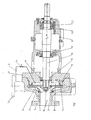
- Fig. 1 shows the impeller 2 has in the region of the impeller inlet via a suction-side throttle gap in the form of a gap seal 4, which ensures a high pressure in the suction side impeller side space 5 and reduces gap losses.
- the impeller 2 on a larger diameter on a second, here pressure-side gap seal 6, which ensures a high pressure in the larger side diameter impeller side space 7 in the larger diameter range.
- the pressure-side gap seal 6 bounded or enveloped with its diameter a arranged on a smaller diameter discharge chamber 8, which is connected via a connection 13 with an adjustable throttle device 14 disposed therein with a location other pressure, here the discharge nozzle 15 of the centrifugal pump.
- the connection 13 may be designed as a conventional conduit system.
- the in Fig. 1 selected location other pressure has a higher pressure than that of the discharge chamber 8 and the choice of location is dependent on the subsequent operating conditions of a pump.
- the location of other pressure may be in the area of the impeller outlet, a guide, the discharge nozzle or the location is as an external Pressure reservoir formed.
- the pressure level on the impeller back or in the impeller side impeller range is set to a value. From the area ratios in the suction-side impeller side space 5, in the pressure-side impeller side space 7 and in the relief space 8 as well as the pressures in these spaces, different forces result. Another force results from the pressure in the suction port 18 in conjunction with a shaft seal 17 in the space 16, since the latter seals against atmospheric pressure from the pressure loads on the impeller 2 results in a defined axial force F A, the impeller 2 and the driving shaft 10 in the direction of Rolling 11 to 11.2 pushes.
- the rolling bearing 11 is formed in the embodiment shown as a pure radial bearing, while two paired bearings 11.1 and 11.2 record the radial and axial forces due to their training. They consist of two angular contact ball bearings, whereby other types of rolling bearings are applicable.
- the shaft 10 which is mounted here in a bearing carrier 12, may also be formed with elimination of the bearing carrier as part of a driving electric motor.
- the bearings of the motor are dimensioned accordingly to accommodate an axial thrust of the pump can.
- the appropriately designed bearing support 12 or the pump cover 3 can be provided with a - known per se, not shown here - short stub shaft, which would be held only in a rolling bearing 11.1. Their shaft end would then be connected to a stub shaft of a block motor.
- the pressure level in the discharge chamber 8 is set during operation over a wide range of values.
- relief holes 9 on the impeller 2 is no longer necessary and available.
- the pressure in the relief chamber 8 and a shaft seal chamber 16 is adjusted so that a resulting axial force F A is formed as a fixed bearing shaft bearing in the form of rolling bearings 11.1, 11.2 always below their allowable limits.
- a resulting axial force F A is formed as a fixed bearing shaft bearing in the form of rolling bearings 11.1, 11.2 always below their allowable limits.
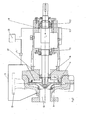
- Fig. 2 corresponds in structure to the illustration in Fig. 1 However, wherein the pressure-side discharge chamber 8 via the connection 13 with the suction side 18 of the centrifugal pump is in operative connection. Also in this case, the impeller 2 is equipped with no relief holes. Instead, the pressure level in the discharge chamber 8 and shaft seal chamber 16 is adjusted by means of the adjustable throttle device 14.1 so that the load on the shaft seal 17 and the rolling bearing 11.1, 11.2 always below the allowable bearings Limits are.
- a sensor 19 which is connected to a controller 20 is used. Changes in the storage condition are detected by the sensor 19 and passed on to the controller 20 on. This determines a controller signal, with the aid of which the controllable throttle device 14.1 adjusted and the permissible axial force F A is set again.
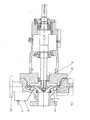
- Fig. 3 shows a variant in which a suction-side relief space 21 is formed by a second, arranged on a larger diameter, suction-side throttle gap in the form of a gap seal 22 with a gap diameter D and a gap width s.
- the in the Fig. 1 and 2 represented pressure-side relief space is omitted in this variant.
- This suction-side relief chamber 21 is connected via the connection 13 with integrated throttle device 14 with the pressure range from the discharge nozzle 15 connected to the centrifugal pump. By appropriate adjustment of the throttle device 14, the generation of the continuous axial force F A is ensured.
- Fig. 4 shows a variant of Fig. 3 , wherein the centrifugal pump is designed for operation with a very high inlet pressure.
- the suction-side relief space 21 is connected to the suction region 18 via the pressure-carrying connection 13 in order to ensure the defined axial force F A on the shaft bearing 11.1, 11.2.
- the axial force F A can be influenced.
- the axial forces receiving bearing which consists of two bearings 11.1, 11.2 in the form of angular contact ball bearings, arranged a bearing load sensor, which continuously determines the axial force. He may as well in the embodiments of the Fig. 1 and 3 Find use. It provides a signal to a control device 20, which compares a respective existing axial force F A with a stored setpoint. In the event of a deviation, the control device 20 generates a control signal for an adjustable throttle device 14.1. This regulates the pressure in the relief chamber 8 or 21 to a value which has a defined, low axial force F A for the rolling bearings 11.1, 11.2 result.
Landscapes
- Engineering & Computer Science (AREA)
- Mechanical Engineering (AREA)
- General Engineering & Computer Science (AREA)
- Physics & Mathematics (AREA)
- Fluid Mechanics (AREA)
- Control Of Non-Positive-Displacement Pumps (AREA)
- Structures Of Non-Positive Displacement Pumps (AREA)
Claims (8)
- Pompe centrifuge à un étage comprenant un dispositif de compensation de la poussée axiale, dans laquelle un rotor connecté à un arbre est disposé de manière rotative dans le carter de la pompe centrifuge, au moins une garniture d'étanchéité annulaire à fente (6) disposée entre le rotor (2) et le carter formant un espace de détente, l'espace de détente étant raccordé avec une connexion transmettant la pression (13) à la partie pression de la pompe centrifuge, et entre l'arbre (10) et le carter étant disposée une garniture d'étanchéité d'arbre, caractérisée en ce que l'arbre (10) est pourvu d'au moins un palier à roulement (11.1, 11.2) recevant les forces axiales, et en ce que, par le biais de la connexion (13), une différence de pression entre une pression dans l'espace de détente (8, 21) et un point à une autre pression dans le carter (1) de la pompe centrifuge, en tant que force axiale admissible et de direction constante (FA), presse les parties rotatives de la pompe (2, 10) contre le palier à roulement (11.1, 11.2).
- Pompe centrifuge selon la revendication 1, caractérisée en ce que la force axiale (FA) est inférieure à la contrainte de palier admissible du palier à roulement (11.1, 11.2) recevant les forces.
- Pompe centrifuge selon la revendication 1 ou 2, caractérisée en ce qu'un dispositif d'étranglement (14) disposé dans la connexion (13) ajuste dans l'espace de détente (8, 21), la force axiale (FA) de direction constante produite à partir de la différence de pression sur le palier à roulement (11.1, 11.2).
- Pompe centrifuge selon la revendication 3, caractérisée en ce que le dispositif d'étranglement (14) est réalisé de manière ajustable ou réglable.
- Pompe centrifuge selon la revendication 1, 2, 3 ou 4, caractérisée en ce qu'un espace de détente (8, 21) de pression variable par le biais de la connexion (13) est disposé du côté aspiration ou du côté pression du rotor (2).
- Pompe centrifuge selon l'une quelconque des revendications 1 à 5, caractérisée en ce qu'un capteur (19) détecte une contrainte de palier à roulement, en ce qu'un régulateur (20) produit avec le signal de capteur un signal de commande pour un dispositif d'étranglement réglable (14.1) et en ce que le dispositif d'étranglement (14.1) ajuste dans l'espace de détente (8, 21) une force axiale (FA) de direction constante sollicitant le palier à roulement (11.1, 11.2).
- Pompe centrifuge selon la revendication 6, caractérisée en ce que le capteur (19) détecte une contrainte de palier axiale en termes d'amplitude et de direction.
- Pompe centrifuge selon l'une quelconque des revendications 1 à 7, caractérisée en ce qu'une ou plusieurs caractéristiques de réglage déposées dans le régulateur (20) corrigent les influences modifiant la contrainte de palier axiale.
Applications Claiming Priority (2)
| Application Number | Priority Date | Filing Date | Title |
|---|---|---|---|
| DE102006011613A DE102006011613A1 (de) | 2006-03-14 | 2006-03-14 | Kreiselpumpe mit Axialschubausgleichseinrichtung |
| PCT/EP2007/002178 WO2007104526A1 (fr) | 2006-03-14 | 2007-03-13 | Pompe centrifuge a dispositif de compensation de la poussee axiale |
Publications (2)
| Publication Number | Publication Date |
|---|---|
| EP1977112A1 EP1977112A1 (fr) | 2008-10-08 |
| EP1977112B1 true EP1977112B1 (fr) | 2010-05-05 |
Family
ID=38141232
Family Applications (1)
| Application Number | Title | Priority Date | Filing Date |
|---|---|---|---|
| EP07711923A Active EP1977112B1 (fr) | 2006-03-14 | 2007-03-13 | Pompe centrifuge a dispositif de compensation de la poussee axiale |
Country Status (5)
| Country | Link |
|---|---|
| EP (1) | EP1977112B1 (fr) |
| AR (1) | AR059835A1 (fr) |
| AT (1) | ATE467051T1 (fr) |
| DE (2) | DE102006011613A1 (fr) |
| WO (1) | WO2007104526A1 (fr) |
Families Citing this family (5)
| Publication number | Priority date | Publication date | Assignee | Title |
|---|---|---|---|---|
| DE102018108827B3 (de) | 2018-04-13 | 2019-05-29 | Trumpf Schweiz Ag | Verfahren zur Steuerung von zumindest einem Radialgebläse in einer Kälteanlage sowie Radialgebläse |
| CN108939182B (zh) * | 2018-09-14 | 2023-10-13 | 长治市久安人工心脏科技开发有限公司 | 一种用于人工心脏轴流泵的磁卸载控制及检测系统 |
| CN112145449B (zh) * | 2020-10-08 | 2022-06-07 | 兰州理工大学 | 一种离心泵的活塞式叶轮轴向力测试装置 |
| CN118103600A (zh) * | 2021-09-21 | 2024-05-28 | 斯凯孚公司 | 泵的轴承配置和操作方法 |
| CN120667393A (zh) * | 2025-08-22 | 2025-09-19 | 山东天瑞重工有限公司 | 一种离心式压缩机及其控制方法 |
Family Cites Families (8)
| Publication number | Priority date | Publication date | Assignee | Title |
|---|---|---|---|---|
| DE1703049B2 (de) * | 1968-03-26 | 1974-09-26 | Allweiler Ag, 7760 Radolfzell | Bausatz von Kreiselpumpen |
| DE2043550C2 (de) * | 1970-01-07 | 1985-10-03 | Judson S. Los Angeles Calif. Swearingen | Steuervorrichtung für den Axialschubausgleich einer hydrodynamischen Drucklageranordnung |
| DE3122810A1 (de) * | 1981-06-09 | 1982-12-30 | Rotoflow Corp., 90064 Los Angeles, Calif. | Wellenbefestigungsvorrichtung |
| EP0078345A1 (fr) * | 1981-10-31 | 1983-05-11 | Bran & Lübbe GmbH | Pompe centrifuge à poussée axiale compensée entraînée, par un moteur à tube d'entrefer |
| JPS59160093A (ja) * | 1983-03-04 | 1984-09-10 | Hitachi Ltd | サブマ−ジブルポンプの軸スラスト荷重低減装置 |
| US5248239A (en) * | 1992-03-19 | 1993-09-28 | Acd, Inc. | Thrust control system for fluid handling rotary apparatus |
| DE19631824A1 (de) * | 1996-08-07 | 1998-02-12 | Klein Schanzlin & Becker Ag | Kreiselpumpenlagerung mit Axialschubausgleich |
| US5980114A (en) * | 1997-01-20 | 1999-11-09 | Oklejas, Jr.; Eli | Thrust bearing |
-
2006
- 2006-03-14 DE DE102006011613A patent/DE102006011613A1/de not_active Withdrawn
-
2007
- 2007-03-13 AT AT07711923T patent/ATE467051T1/de active
- 2007-03-13 DE DE502007003649T patent/DE502007003649D1/de active Active
- 2007-03-13 WO PCT/EP2007/002178 patent/WO2007104526A1/fr not_active Ceased
- 2007-03-13 EP EP07711923A patent/EP1977112B1/fr active Active
- 2007-03-14 AR ARP070101029A patent/AR059835A1/es not_active Application Discontinuation
Also Published As
| Publication number | Publication date |
|---|---|
| AR059835A1 (es) | 2008-04-30 |
| DE502007003649D1 (fr) | 2010-06-17 |
| WO2007104526A1 (fr) | 2007-09-20 |
| EP1977112A1 (fr) | 2008-10-08 |
| ATE467051T1 (de) | 2010-05-15 |
| DE102006011613A1 (de) | 2007-09-20 |
Similar Documents
| Publication | Publication Date | Title |
|---|---|---|
| DE69313560T2 (de) | Hydraulische Flügelzellenpumpe mit verbessertem axialen Druckausgleich und verbesserten Druckflusseigenschaften | |
| EP0750720B1 (fr) | Turbomachine avec piston d'allegement | |
| DE69105951T2 (de) | Schraubenkolbenmaschine mit schubausgleichsmitteln. | |
| DE2105485B2 (fr) | ||
| EP1281836A2 (fr) | Turbomachine | |
| EP1977112B1 (fr) | Pompe centrifuge a dispositif de compensation de la poussee axiale | |
| EP1953390A1 (fr) | Dispositif et procédé d'égalisation de poussée axiale | |
| EP3071840B1 (fr) | Dispositif de décharge | |
| DE4005428A1 (de) | Sperrfluessigkeits-dichtungsanordnung bei einem turboverdichter | |
| DE2460282A1 (de) | Zentrifugalpumpe | |
| DE102019110767A1 (de) | Pumpe mit variabler verdrängung | |
| EP0443472B1 (fr) | Dispositif d'étanchéité avec liquide d'arrêt pour turbo-compresseur | |
| EP0405161B1 (fr) | Pompe à rotors hélicoidaux | |
| WO2004109117A1 (fr) | Pompe centrifuge multi-etagee | |
| EP2084395B1 (fr) | Ensemble de joint d'étanchéité entre deux parties mobiles l'une par rapport à l'autre d'une turbomachine | |
| DE1815088A1 (de) | Axialschubausgleich bei Spaltrohrmotorpumpen | |
| EP0221300B1 (fr) | Dispositif de pompe centrifuge | |
| DE19631824A1 (de) | Kreiselpumpenlagerung mit Axialschubausgleich | |
| DE4108126C2 (de) | Flügelzellenpumpe | |
| DE3537449A1 (de) | Lagerung mit schwimmenden buechsen | |
| DE3608289A1 (de) | Turboverdichter | |
| EP0461131A1 (fr) | Dispositif d'equilibrage de poussees axiales. | |
| DE2402017A1 (de) | Rotationskolbenpumpe, insbesondere fuer servolenkungen von kraftfahrzeugen | |
| DE2138832A1 (de) | Elektro Kreiselpumpe mit flachem Luft spalt und frei aufgehängtem Rotor | |
| EP1305525B1 (fr) | Dispositif de compensation de la poussee axiale |
Legal Events
| Date | Code | Title | Description |
|---|---|---|---|
| PUAI | Public reference made under article 153(3) epc to a published international application that has entered the european phase |
Free format text: ORIGINAL CODE: 0009012 |
|
| 17P | Request for examination filed |
Effective date: 20080612 |
|
| AK | Designated contracting states |
Kind code of ref document: A1 Designated state(s): AT BE BG CH CY CZ DE DK EE ES FI FR GB GR HU IE IS IT LI LT LU LV MC MT NL PL PT RO SE SI SK TR |
|
| 17Q | First examination report despatched |
Effective date: 20081201 |
|
| GRAP | Despatch of communication of intention to grant a patent |
Free format text: ORIGINAL CODE: EPIDOSNIGR1 |
|
| DAX | Request for extension of the european patent (deleted) | ||
| GRAS | Grant fee paid |
Free format text: ORIGINAL CODE: EPIDOSNIGR3 |
|
| GRAA | (expected) grant |
Free format text: ORIGINAL CODE: 0009210 |
|
| AK | Designated contracting states |
Kind code of ref document: B1 Designated state(s): AT BE BG CH CY CZ DE DK EE ES FI FR GB GR HU IE IS IT LI LT LU LV MC MT NL PL PT RO SE SI SK TR |
|
| REG | Reference to a national code |
Ref country code: GB Ref legal event code: FG4D Free format text: NOT ENGLISH |
|
| REG | Reference to a national code |
Ref country code: CH Ref legal event code: EP |
|
| REG | Reference to a national code |
Ref country code: IE Ref legal event code: FG4D Free format text: LANGUAGE OF EP DOCUMENT: GERMAN |
|
| REF | Corresponds to: |
Ref document number: 502007003649 Country of ref document: DE Date of ref document: 20100617 Kind code of ref document: P |
|
| REG | Reference to a national code |
Ref country code: NL Ref legal event code: VDEP Effective date: 20100505 |
|
| LTIE | Lt: invalidation of european patent or patent extension |
Effective date: 20100505 |
|
| PG25 | Lapsed in a contracting state [announced via postgrant information from national office to epo] |
Ref country code: NL Free format text: LAPSE BECAUSE OF FAILURE TO SUBMIT A TRANSLATION OF THE DESCRIPTION OR TO PAY THE FEE WITHIN THE PRESCRIBED TIME-LIMIT Effective date: 20100505 Ref country code: ES Free format text: LAPSE BECAUSE OF FAILURE TO SUBMIT A TRANSLATION OF THE DESCRIPTION OR TO PAY THE FEE WITHIN THE PRESCRIBED TIME-LIMIT Effective date: 20100816 Ref country code: LT Free format text: LAPSE BECAUSE OF FAILURE TO SUBMIT A TRANSLATION OF THE DESCRIPTION OR TO PAY THE FEE WITHIN THE PRESCRIBED TIME-LIMIT Effective date: 20100505 Ref country code: SE Free format text: LAPSE BECAUSE OF FAILURE TO SUBMIT A TRANSLATION OF THE DESCRIPTION OR TO PAY THE FEE WITHIN THE PRESCRIBED TIME-LIMIT Effective date: 20100505 |
|
| PG25 | Lapsed in a contracting state [announced via postgrant information from national office to epo] |
Ref country code: SI Free format text: LAPSE BECAUSE OF FAILURE TO SUBMIT A TRANSLATION OF THE DESCRIPTION OR TO PAY THE FEE WITHIN THE PRESCRIBED TIME-LIMIT Effective date: 20100505 Ref country code: FI Free format text: LAPSE BECAUSE OF FAILURE TO SUBMIT A TRANSLATION OF THE DESCRIPTION OR TO PAY THE FEE WITHIN THE PRESCRIBED TIME-LIMIT Effective date: 20100505 Ref country code: IS Free format text: LAPSE BECAUSE OF FAILURE TO SUBMIT A TRANSLATION OF THE DESCRIPTION OR TO PAY THE FEE WITHIN THE PRESCRIBED TIME-LIMIT Effective date: 20100905 Ref country code: LV Free format text: LAPSE BECAUSE OF FAILURE TO SUBMIT A TRANSLATION OF THE DESCRIPTION OR TO PAY THE FEE WITHIN THE PRESCRIBED TIME-LIMIT Effective date: 20100505 |
|
| REG | Reference to a national code |
Ref country code: IE Ref legal event code: FD4D |
|
| PG25 | Lapsed in a contracting state [announced via postgrant information from national office to epo] |
Ref country code: CY Free format text: LAPSE BECAUSE OF FAILURE TO SUBMIT A TRANSLATION OF THE DESCRIPTION OR TO PAY THE FEE WITHIN THE PRESCRIBED TIME-LIMIT Effective date: 20100602 Ref country code: PL Free format text: LAPSE BECAUSE OF FAILURE TO SUBMIT A TRANSLATION OF THE DESCRIPTION OR TO PAY THE FEE WITHIN THE PRESCRIBED TIME-LIMIT Effective date: 20100505 |
|
| PG25 | Lapsed in a contracting state [announced via postgrant information from national office to epo] |
Ref country code: EE Free format text: LAPSE BECAUSE OF FAILURE TO SUBMIT A TRANSLATION OF THE DESCRIPTION OR TO PAY THE FEE WITHIN THE PRESCRIBED TIME-LIMIT Effective date: 20100505 Ref country code: IE Free format text: LAPSE BECAUSE OF FAILURE TO SUBMIT A TRANSLATION OF THE DESCRIPTION OR TO PAY THE FEE WITHIN THE PRESCRIBED TIME-LIMIT Effective date: 20100505 Ref country code: DK Free format text: LAPSE BECAUSE OF FAILURE TO SUBMIT A TRANSLATION OF THE DESCRIPTION OR TO PAY THE FEE WITHIN THE PRESCRIBED TIME-LIMIT Effective date: 20100505 Ref country code: PT Free format text: LAPSE BECAUSE OF FAILURE TO SUBMIT A TRANSLATION OF THE DESCRIPTION OR TO PAY THE FEE WITHIN THE PRESCRIBED TIME-LIMIT Effective date: 20100906 |
|
| PG25 | Lapsed in a contracting state [announced via postgrant information from national office to epo] |
Ref country code: CZ Free format text: LAPSE BECAUSE OF FAILURE TO SUBMIT A TRANSLATION OF THE DESCRIPTION OR TO PAY THE FEE WITHIN THE PRESCRIBED TIME-LIMIT Effective date: 20100505 Ref country code: SK Free format text: LAPSE BECAUSE OF FAILURE TO SUBMIT A TRANSLATION OF THE DESCRIPTION OR TO PAY THE FEE WITHIN THE PRESCRIBED TIME-LIMIT Effective date: 20100505 Ref country code: RO Free format text: LAPSE BECAUSE OF FAILURE TO SUBMIT A TRANSLATION OF THE DESCRIPTION OR TO PAY THE FEE WITHIN THE PRESCRIBED TIME-LIMIT Effective date: 20100505 |
|
| PLBE | No opposition filed within time limit |
Free format text: ORIGINAL CODE: 0009261 |
|
| STAA | Information on the status of an ep patent application or granted ep patent |
Free format text: STATUS: NO OPPOSITION FILED WITHIN TIME LIMIT |
|
| 26N | No opposition filed |
Effective date: 20110208 |
|
| REG | Reference to a national code |
Ref country code: DE Ref legal event code: R097 Ref document number: 502007003649 Country of ref document: DE Effective date: 20110207 |
|
| PG25 | Lapsed in a contracting state [announced via postgrant information from national office to epo] |
Ref country code: GR Free format text: LAPSE BECAUSE OF FAILURE TO SUBMIT A TRANSLATION OF THE DESCRIPTION OR TO PAY THE FEE WITHIN THE PRESCRIBED TIME-LIMIT Effective date: 20100806 |
|
| BERE | Be: lapsed |
Owner name: KSB A.G. Effective date: 20110331 |
|
| PG25 | Lapsed in a contracting state [announced via postgrant information from national office to epo] |
Ref country code: MC Free format text: LAPSE BECAUSE OF NON-PAYMENT OF DUE FEES Effective date: 20110331 |
|
| PG25 | Lapsed in a contracting state [announced via postgrant information from national office to epo] |
Ref country code: MT Free format text: LAPSE BECAUSE OF FAILURE TO SUBMIT A TRANSLATION OF THE DESCRIPTION OR TO PAY THE FEE WITHIN THE PRESCRIBED TIME-LIMIT Effective date: 20100505 Ref country code: BE Free format text: LAPSE BECAUSE OF NON-PAYMENT OF DUE FEES Effective date: 20110331 |
|
| PG25 | Lapsed in a contracting state [announced via postgrant information from national office to epo] |
Ref country code: LU Free format text: LAPSE BECAUSE OF NON-PAYMENT OF DUE FEES Effective date: 20110313 |
|
| PG25 | Lapsed in a contracting state [announced via postgrant information from national office to epo] |
Ref country code: BG Free format text: LAPSE BECAUSE OF FAILURE TO SUBMIT A TRANSLATION OF THE DESCRIPTION OR TO PAY THE FEE WITHIN THE PRESCRIBED TIME-LIMIT Effective date: 20100805 Ref country code: TR Free format text: LAPSE BECAUSE OF FAILURE TO SUBMIT A TRANSLATION OF THE DESCRIPTION OR TO PAY THE FEE WITHIN THE PRESCRIBED TIME-LIMIT Effective date: 20100505 |
|
| PG25 | Lapsed in a contracting state [announced via postgrant information from national office to epo] |
Ref country code: HU Free format text: LAPSE BECAUSE OF FAILURE TO SUBMIT A TRANSLATION OF THE DESCRIPTION OR TO PAY THE FEE WITHIN THE PRESCRIBED TIME-LIMIT Effective date: 20100505 |
|
| REG | Reference to a national code |
Ref country code: FR Ref legal event code: PLFP Year of fee payment: 10 |
|
| REG | Reference to a national code |
Ref country code: FR Ref legal event code: PLFP Year of fee payment: 11 |
|
| PGFP | Annual fee paid to national office [announced via postgrant information from national office to epo] |
Ref country code: CH Payment date: 20170323 Year of fee payment: 11 |
|
| PGFP | Annual fee paid to national office [announced via postgrant information from national office to epo] |
Ref country code: AT Payment date: 20170330 Year of fee payment: 11 |
|
| PGFP | Annual fee paid to national office [announced via postgrant information from national office to epo] |
Ref country code: IT Payment date: 20170331 Year of fee payment: 11 |
|
| REG | Reference to a national code |
Ref country code: DE Ref legal event code: R081 Ref document number: 502007003649 Country of ref document: DE Owner name: KSB SE & CO. KGAA, DE Free format text: FORMER OWNER: KSB AG, 67227 FRANKENTHAL, DE |
|
| REG | Reference to a national code |
Ref country code: FR Ref legal event code: PLFP Year of fee payment: 12 |
|
| REG | Reference to a national code |
Ref country code: CH Ref legal event code: PL |
|
| REG | Reference to a national code |
Ref country code: AT Ref legal event code: MM01 Ref document number: 467051 Country of ref document: AT Kind code of ref document: T Effective date: 20180313 |
|
| PG25 | Lapsed in a contracting state [announced via postgrant information from national office to epo] |
Ref country code: AT Free format text: LAPSE BECAUSE OF NON-PAYMENT OF DUE FEES Effective date: 20180313 |
|
| PG25 | Lapsed in a contracting state [announced via postgrant information from national office to epo] |
Ref country code: IT Free format text: LAPSE BECAUSE OF NON-PAYMENT OF DUE FEES Effective date: 20180313 Ref country code: CH Free format text: LAPSE BECAUSE OF NON-PAYMENT OF DUE FEES Effective date: 20180331 Ref country code: LI Free format text: LAPSE BECAUSE OF NON-PAYMENT OF DUE FEES Effective date: 20180331 |
|
| PGFP | Annual fee paid to national office [announced via postgrant information from national office to epo] |
Ref country code: FR Payment date: 20250326 Year of fee payment: 19 |
|
| PGFP | Annual fee paid to national office [announced via postgrant information from national office to epo] |
Ref country code: GB Payment date: 20250322 Year of fee payment: 19 |
|
| PGFP | Annual fee paid to national office [announced via postgrant information from national office to epo] |
Ref country code: DE Payment date: 20250403 Year of fee payment: 19 |