EP1977177B1 - Convective system for a dryer installation - Google Patents
Convective system for a dryer installation Download PDFInfo
- Publication number
- EP1977177B1 EP1977177B1 EP07704124.2A EP07704124A EP1977177B1 EP 1977177 B1 EP1977177 B1 EP 1977177B1 EP 07704124 A EP07704124 A EP 07704124A EP 1977177 B1 EP1977177 B1 EP 1977177B1
- Authority
- EP
- European Patent Office
- Prior art keywords
- web
- combustion products
- casing
- convective
- gas
- Prior art date
- Legal status (The legal status is an assumption and is not a legal conclusion. Google has not performed a legal analysis and makes no representation as to the accuracy of the status listed.)
- Active
Links
Images



Classifications
-
- F—MECHANICAL ENGINEERING; LIGHTING; HEATING; WEAPONS; BLASTING
- F26—DRYING
- F26B—DRYING SOLID MATERIALS OR OBJECTS BY REMOVING LIQUID THEREFROM
- F26B3/00—Drying solid materials or objects by processes involving the application of heat
- F26B3/28—Drying solid materials or objects by processes involving the application of heat by radiation, e.g. from the sun
- F26B3/30—Drying solid materials or objects by processes involving the application of heat by radiation, e.g. from the sun from infrared-emitting elements
- F26B3/305—Drying solid materials or objects by processes involving the application of heat by radiation, e.g. from the sun from infrared-emitting elements the infrared radiation being generated by combustion or combustion gases
-
- D—TEXTILES; PAPER
- D21—PAPER-MAKING; PRODUCTION OF CELLULOSE
- D21F—PAPER-MAKING MACHINES; METHODS OF PRODUCING PAPER THEREON
- D21F5/00—Dryer section of machines for making continuous webs of paper
- D21F5/008—Drying webs by direct contact with gas flames
-
- F—MECHANICAL ENGINEERING; LIGHTING; HEATING; WEAPONS; BLASTING
- F26—DRYING
- F26B—DRYING SOLID MATERIALS OR OBJECTS BY REMOVING LIQUID THEREFROM
- F26B13/00—Machines and apparatus for drying fabrics, fibres, yarns, or other materials in long lengths, with progressive movement
- F26B13/10—Arrangements for feeding, heating or supporting materials; Controlling movement, tension or position of materials
-
- F—MECHANICAL ENGINEERING; LIGHTING; HEATING; WEAPONS; BLASTING
- F26—DRYING
- F26B—DRYING SOLID MATERIALS OR OBJECTS BY REMOVING LIQUID THEREFROM
- F26B13/00—Machines and apparatus for drying fabrics, fibres, yarns, or other materials in long lengths, with progressive movement
- F26B13/10—Arrangements for feeding, heating or supporting materials; Controlling movement, tension or position of materials
- F26B13/22—Arrangements of gas flames
Definitions
- the present invention concerns a convective system for a dryer installation for a passing web, more particularly paper.
- an installation having at least a web, gas-heated radiant elements arranged according to at least one row stretching out in the transversal direction of the web, substantially over its entire width, and, downstream at least one row of radiant elements, at least a transversal convective system equipped with suction and blowing devices to suck at least part of the combustion products produced by the radiant elements and to blow this part of the combustion products towards the web.
- the installation generally also has devices to extract the warm gasses resulting from the convective exchanges between the passing web and the combustion products.
- the suction and blowing devices have a mixing device, such as e.g. a ventilator, that is, for several known reasons, shifted laterally at the outside of the web, in relation to the median longitudinal axis usually at a large, even extremely large, distance in relation to the width of the web.
- a mixing device such as e.g. a ventilator
- the ventilator has to laterally collect the combustion products that are initially divided over the entire width of the web, mix the combustion products and divide them again over the entire width of the web.
- Such a mixing entails an important consumption of energy.
- the temperature of the combustion products blown on the web is considerably lower than the temperature of the combustion products generated by the radiant elements.
- This dryer installation is characterized by the fact that the suction and blowing devices of the convective system have at least one suction and blowing device installed opposite of the passing web in relation to corresponding suction and blowing ducts that at least stretch out in the transversal direction of the web, and arranged so as to suck and/or blow the said combustion products in such a way that the vector averages are optimized.
- the vectors are representing the respective trajectories of the different jets of sucked and/or blown combustion products.
- the temperature difference between the sucked combustion products and the blown combustion products is substantially reduced, thereby increasing the efficiency.
- the objective of the present invention is to mitigate the restrictions of the known installations and to propose a dryer installation having a more reduced consumption of mechanical energy and a more reduced loss of thermal energy and lower investment and operation costs.
- the convective system has an internal casing inside the external casing.
- This internal casing has at least one opening towards the web and has also openings allowing gas flow from the external casing to the internal casing of said gas mixture.
- the second suction duct is also arranged under this internal casing thereby extracting a second flow of combustion products into the internal casing.
- This second flow of combustion products is then mixed with the gas mixture with lower temperature coming from the mixing device, resulting in a mixture of gasses with a temperature that is higher than the first gas mixture and higher than e.g. 350°C, more preferably 400°C or 450 °C, even more preferably 500°C.
- These hot gasses are then blown to the drying web by the blowing duct of the internal casing.
- this improved convective system can be achieved by simple means, by applying an inner casing into the outer casing. It is clear that applying an inner casing can be done without difficulties, thus in a simple way.
- the convective system is constructed with a mixing and blowing device being a venturi-system.
- the convective system is designed in such a way that the blowing duct is arranged between said first suction duct and said second suction duct.
- a preferable embodiment of the invention provides a special design of the internal casing resulting in a good air distribution.
- Another preferred embodiment of the invention provides in the system an air pressure sensor in order to assure constant flotation effect on the web to be dried.
- a temperature sensor can also be foreseen.
- a preferred embodiment of the invention is the convective system wherein the mixing and blowing device at least has one turbine of which the axis is perpendicular to the web.
- Another version of the invention is the convective system wherein the mixing and blowing device at least has one turbine of which the axis is parallel to the web.
- the use of the dryer installation provides a method for safeguarding a fan from contact with hot combustion gasses by using above described convective system.
- the use of the dryer installation provides a method of re-using heated gasses to enhance the heat exchanging efficiency using the above described convective system.
- the dryer installation is designed for drying a maximum web width and is composed of gas-heated radiant elements for radiating said web next to the convective system.
- the radiant elements are arranged in at least one row stretching out in the transversal direction over the substantially entire maximum web width.
- a further implementation of the invention is an installation which has at least two transversal convective systems arranged one after the other in the passing direction of the web and separated one from the other by at least one transversal row of gas-heated radiant elements.
- the dryer installation can be based on a burner assembly, said dryer installation e.g. being of a flame drier type.
- the system of re-using the exhaust gases is set up in a cascade system, wherein the exhaust gasses coming directly from the heating assembly (e.g. burner system, gas-heated radiant elements) are sucked and blown to the web by a first convective system.
- the warm gasses which are then available at the second convective system are again sucked for re-use and re-blown thereby making further use of the available thermal energy which was created by the heating assembly.
- the heating assembly e.g. burner system, gas-heated radiant elements
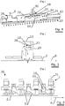
- Figure 1 represents a dryer installation 1 for a passing web 2, more particularly paper, e. g. for a web of coated paper that has been treated in a humid way and has to be dried without contact.
- the installation 1 has at least the web 2 and the gas-heated radiant elements 3.
- the elements 3 are arranged according to at least one row 4 stretching out in the transversal direction 5 of the web 2.
- the row 4 substantially stretches over the entire maximum web width.
- the installation 1 also has at least one convective system 7 downstream of at least one row 4 of radiant elements 3, referring to the direction of the passing of the web 6.
- the convective system includes suction and blowing devices 8.
- the devices 8 suck at least a part of the combustion products generated by the radiant elements 3 and blow those combustion products towards the web 2.
- the convective system also has devices 9 to extract the warm gasses resulting from the convective thermal exchanges between the passing web 2 and those combustion products.
- the radiant elements 3 can be gas-heated radiant elements of whatever type, arranged in any possible way in relation to one another and in relation to gas supply tubes, and to combustion air supply tubes.
- the suction and blowing devices 8 include at least one mixing device 12 installed opposite of the passing web 2.
- Figure 2 represents a section of the convective system 7 according to a plane perpendicular to the web that stretches out in the longitudinal direction of the web (according to B-B').
- Figure 3 shows the respective gas flows in the convective system:
- the convective system 7 is an assembly of an exterior casing 13 for suction of combustion products with opening 14 towards the web, with a first 15 and second 16 suction ducts sucking the combustion products into the convective system 7.
- the combustion products coming from the first suction duct 15 are guided through the exterior casing 13 to a mixing and blowing device 17.
- Cold air 18 is mixed in this mixing and blowing device 17 with the combustion products 19, resulting in a gas mixture with lower temperature 20.
- the convective system 7 also has an internal casing 21 inside the external casing 13.
- This internal casing 21 has at least one opening towards the web 22 and has also openings 34 allowing gas flow from the mixing device 17 to the internal casing 21 of said gas mixture 20.
- the second suction duct 16 is also arranged under this internal casing 21 thereby extracting a second flow of combustion products 24 into the internal casing 21.
- This second flow 24 of combustion products is then mixed with the gas mixture 20 coming from the mixing device 17, resulting in a mixture of gasses 25 with a temperature that is higher than the first gas mixture 20 and higher than e.g. 350°C or 370°C, more preferably 390° C or 410°C, even more preferably 420°C, 450°C or 500°C.
- These hot gasses 25 are then blown to the drying web by the blowing duct 23 of the internal casing 21.
- Figure 3B depicts an alternative embodiment following the same principle as in Figure 3A .
- Figure 4 is a cross-section, according to a plane perpendicular to the web 2 that stretches out in the transversal direction of the web (according to A-A'), of the convective system 7.
- the suction ducts 15 and 16 and blowing duct 23 stretch out over the total web width, but are not indicated in this figure.
- the convective system 7 can preferably be designed as indicated in figure 4 .
- the internal casing 21 comprises also an extraction duct 26 that is part of the devices 9.
- the extraction duct 26 extracts part of the warm gasses 25 and part of the combustion gasses 19.
- This extraction duct 26 is asymmetrically arranged in the convective system 7.
- the inner height of the internal casing 21 is also asymmetric and increases towards the extraction duct 26.
- the devices 9 are known extraction devices, e.g. a fan.
- each turbine 30 has a centrifugal turbine wheel of which the suction opening 32 is connected to an upstream transversal suction duct 15 in relation to the web 2.
- the wheel is driven by an engine, as in any conventional fan.
- the mixed gasses 20 are blown through two tangential outlet openings 33 substantially directly opposite to the transversal direction 5 of the web 2, and connected to two transversal blowing ducts 34.
- Figure 5 shows a mixing and blowing device of the convective system that has at least one turbine of which the axis is parallel to the web.
- a cylindrical rotor 27 is installed at the interior side of the first external casing 13. Each cylindrical rotor 27 is installed inside a corresponding enclosed space 28 and has radial blades. Each cylindrical rotor 27 turns around a respective axis 29 parallel to the web 2 and substantially perpendicular to the passing direction 6 of the web 2.
- the different rotors 27 are installed on the same pole driven by an engine.
- Another preferred embodiment of the invention comprises a convective system 7 wherein the mixing and blowing device at least has one turbine of which the axis is perpendicular to the web, as in e.g. a fan.
- This axis can also be given other directions inclined in any possible direction in relation to the web, without leaving the scope of the present invention.
- each convective system 7 at least has one turbine 30 of which the axis 31 is substantially perpendicular to the web 2.
- Each convective system can have a fresh air inlet opening, along a lateral edge of the web 2, for instance in the right-hand side of figure 4 .
- This fresh air inlet is advantageously closed off by a valve to allow the entrance of ambient temperature air inside the suction duct 15 in order to dilute the combustion products and thus limit the temperature of the combustion products sucked by turbine 30, if necessary.
- each convective system 7 also has an extraction opening as described above.
- Another preferred embodiment of the invention comprises a convective system wherein the mixing device 12 is an organ adapted to blow air under pressure through the openings 33 of figure 4 . This creates a venturi effect which sucks at least part of the combustion products through the suction duct 15 and blows them in the internal casing 21.
- the afore-described mixing devices can also be arranged in a different way than the ways described above.
- an arrangement of such radiant elements and convective systems can be put on each side of the web to be dried.
- the devices of the invention described above, the suction ducts 15 and 16 and the blowing duct 23, the mixing devices 30, the exterior 13 and interior casing 21, etc. are designed and arranged in a known way so that they can endure durably and reliably the high temperatures of the sucked and/or blown combustion products.
- this so called cascade system the exhaust gases are coming directly from a burner assembly, and are sucked by the convective system whereafter these hot gasses are blown to the web for re-use, by the blowing duct.
- the warm gasses which are then available at the convective system can again be sucked for re-use and re-blown thereby making further use of the available thermal energy which was created by the burner assembly.
- first convective system which blows re-used exhaust gasses at 400°C and thereafter a second convective system which blows gasses at 200°C.
- This cascade system of re-using the created hot-air flows can also be used in other drying systems, e.g. in combination with IR-dryers.
- thermal insulation devices and/or traditional cooling-down devices known to protect certain specific devices, such as e. g. an electrical engine.
Landscapes
- Engineering & Computer Science (AREA)
- Mechanical Engineering (AREA)
- General Engineering & Computer Science (AREA)
- Textile Engineering (AREA)
- Chemical & Material Sciences (AREA)
- Combustion & Propulsion (AREA)
- Life Sciences & Earth Sciences (AREA)
- Microbiology (AREA)
- Drying Of Solid Materials (AREA)
- Nozzles (AREA)
Priority Applications (2)
| Application Number | Priority Date | Filing Date | Title |
|---|---|---|---|
| SI200732036T SI1977177T1 (sl) | 2006-01-25 | 2007-01-24 | Konvekcijski sistem za sušilno napravo |
| EP07704124.2A EP1977177B1 (en) | 2006-01-25 | 2007-01-24 | Convective system for a dryer installation |
Applications Claiming Priority (4)
| Application Number | Priority Date | Filing Date | Title |
|---|---|---|---|
| EP06100857 | 2006-01-25 | ||
| EP06101071 | 2006-01-31 | ||
| PCT/EP2007/050693 WO2007085618A1 (en) | 2006-01-25 | 2007-01-24 | Convective system for a dryer installation |
| EP07704124.2A EP1977177B1 (en) | 2006-01-25 | 2007-01-24 | Convective system for a dryer installation |
Publications (2)
| Publication Number | Publication Date |
|---|---|
| EP1977177A1 EP1977177A1 (en) | 2008-10-08 |
| EP1977177B1 true EP1977177B1 (en) | 2018-03-07 |
Family
ID=38001754
Family Applications (2)
| Application Number | Title | Priority Date | Filing Date |
|---|---|---|---|
| EP07704123A Withdrawn EP1977179A1 (en) | 2006-01-25 | 2007-01-24 | Flame dryer |
| EP07704124.2A Active EP1977177B1 (en) | 2006-01-25 | 2007-01-24 | Convective system for a dryer installation |
Family Applications Before (1)
| Application Number | Title | Priority Date | Filing Date |
|---|---|---|---|
| EP07704123A Withdrawn EP1977179A1 (en) | 2006-01-25 | 2007-01-24 | Flame dryer |
Country Status (7)
| Country | Link |
|---|---|
| US (2) | US20090007453A1 (pt) |
| EP (2) | EP1977179A1 (pt) |
| JP (2) | JP2010516984A (pt) |
| BR (2) | BRPI0707331A2 (pt) |
| ES (1) | ES2664225T3 (pt) |
| SI (1) | SI1977177T1 (pt) |
| WO (2) | WO2007085618A1 (pt) |
Families Citing this family (7)
| Publication number | Priority date | Publication date | Assignee | Title |
|---|---|---|---|---|
| EP1721109B1 (en) * | 2004-03-02 | 2012-04-18 | Solaronics S.A. | Infrared drier installation for passing web |
| FR2867263B1 (fr) * | 2004-03-02 | 2006-05-26 | Solaronics Irt | Installation de sechage pour une bande defilante, notamment pour une bande de papier |
| BRPI0707331A2 (pt) * | 2006-01-25 | 2011-05-03 | Bekaert Sa Nv | sistema de convecção para instalação de secadora |
| WO2011113631A1 (en) * | 2010-03-15 | 2011-09-22 | Solaronics S.A. | Drying installation |
| WO2015030766A1 (en) | 2013-08-29 | 2015-03-05 | Hewlett-Packard Development Company, L.P. | Variable humidity drying |
| DE102017129017A1 (de) | 2017-12-06 | 2019-06-06 | Heraeus Noblelight Gmbh | Verfahren zum Trocknen eines Substrats, Trocknermodul zur Durchführung des Verfahrens sowie Trocknersystem |
| CN108562171A (zh) * | 2018-01-22 | 2018-09-21 | 卢爱玲 | 一种陶瓷窑炉抽湿废气利用系统 |
Family Cites Families (88)
| Publication number | Priority date | Publication date | Assignee | Title |
|---|---|---|---|---|
| US2414891A (en) * | 1944-02-19 | 1947-01-28 | Offen Bernard | Means for drying webs |
| US2668700A (en) * | 1949-05-25 | 1954-02-09 | Richard G Zimmerman | Drier for printing presses |
| US2987305A (en) * | 1957-05-31 | 1961-06-06 | J V Calhoun Company | Methods of and apparatus for generating and transferring heat |
| US3096162A (en) * | 1958-02-19 | 1963-07-02 | Spooner Dryer & Eng Co Ltd | Gaseous restraint of conveyed articles |
| GB877266A (en) * | 1959-02-13 | 1961-09-13 | John Harold Flynn | Method of drying coated webs |
| US3231985A (en) * | 1962-01-15 | 1966-02-01 | Hupp Corp | Heating, drying and curing apparatus and methods |
| GB1153038A (en) * | 1965-12-23 | 1969-05-21 | Nat Res Dev | Improvements in or relating to the Drying of Flexible Material such as Paper and Board Formed from Cellulosic Fibrous Materials |
| AU420345B2 (en) * | 1967-12-29 | 1972-01-10 | Sidney Flynn Charles | High velocity burner assembly |
| US3477138A (en) * | 1968-01-03 | 1969-11-11 | Boxboard Research & Dev Ass | Method and apparatus for web drying |
| US3643342A (en) * | 1969-05-02 | 1972-02-22 | Goodyear Tire & Rubber | Dryer or heater with shielding means |
| US3590495A (en) * | 1969-05-02 | 1971-07-06 | Goodyear Tire & Rubber | Dryer or heater with shielding means |
| JPS5513057Y1 (pt) * | 1970-12-30 | 1980-03-24 | ||
| US3739491A (en) * | 1971-09-22 | 1973-06-19 | Tec Systems | High velocity air web dryer |
| BE791511A (fr) * | 1971-11-19 | 1973-03-16 | Flynn Charles S | Appareil de traitement thermique rapide d'une bande de matiere |
| GB1439919A (en) * | 1972-09-07 | 1976-06-16 | Transparent Paper Ltd | Heat-treatment of travelling webs |
| US3955955A (en) * | 1973-07-11 | 1976-05-11 | Triplex Safety Glass Company Limited | Glass toughening methods |
| USRE30169E (en) * | 1974-01-23 | 1979-12-18 | Method of drying coated webs | |
| US4094627A (en) * | 1974-11-06 | 1978-06-13 | Milton Jr Clare L | Oven system |
| GB1534798A (en) * | 1976-03-12 | 1978-12-06 | Flynn J | Removal of volatile products from webs |
| US4290269A (en) * | 1979-10-09 | 1981-09-22 | Modo-Chemetics Ab | Process for the efficient conversion of water-containing organic materials as fuels into energy |
| US5090898A (en) * | 1979-11-16 | 1992-02-25 | Smith Thomas M | Infra-red heating |
| US5046944A (en) * | 1979-11-16 | 1991-09-10 | Smith Thomas M | Infra-red generation |
| JPS57166092U (pt) * | 1981-04-13 | 1982-10-19 | ||
| JPS6017671Y2 (ja) * | 1981-07-27 | 1985-05-30 | 大日本スクリ−ン製造株式会社 | 温風乾燥装置 |
| DE3148321A1 (de) * | 1981-12-07 | 1983-08-18 | Fleißner GmbH & Co, Maschinenfabrik, 6073 Egelsbach | "vorrichtung zum waermebehandeln von horizontal gefuehrten, bahnfoermigen guetern." |
| JPS59213919A (ja) * | 1983-05-19 | 1984-12-03 | Nippon Clean Engine Res | 層状掃気二サイクル内燃機関 |
| US4498864A (en) * | 1982-12-10 | 1985-02-12 | Techmark Corporation | Method and apparatus for uniformly drying moving webs |
| DE3307284C2 (de) * | 1983-03-02 | 1985-11-14 | Hans Dr.h.c. 3559 Battenberg Vießmann | Gebläsebrenner für Heizkesseltüren |
| JPS60119327A (ja) * | 1983-12-01 | 1985-06-26 | Yamaha Motor Co Ltd | 2サイクル内燃機関 |
| FI69141C (fi) * | 1984-10-09 | 1985-12-10 | Tampella Oy Ab | Foerfarande och anordning foer torkning av en pappersbana eller liknande |
| US4606137A (en) * | 1985-03-28 | 1986-08-19 | Thermo Electron Web Systems, Inc. | Web dryer with control of air infiltration |
| JPH066752B2 (ja) * | 1985-07-29 | 1994-01-26 | 大同特殊鋼株式会社 | フロ−テイング炉における循環ガス供給装置 |
| DE3605100A1 (de) * | 1986-02-18 | 1987-08-27 | Monforts Gmbh & Co A | Textilmaschine mit kontinuierlicher konvektiver waermebehandlung |
| JPS63187017A (ja) * | 1987-01-29 | 1988-08-02 | Ngk Insulators Ltd | 塩素を含む湿潤廃棄物の焼却処理方法 |
| JPS63250422A (ja) * | 1987-04-07 | 1988-10-18 | Mitsubishi Heavy Ind Ltd | 金属帯の浮揚支持方法及び装置 |
| NL8800226A (nl) * | 1988-01-29 | 1989-08-16 | Stork Contiweb | Droger voor een materiaalbaan. |
| FI78756C (fi) * | 1988-04-25 | 1989-09-11 | Valmet Paper Machinery Inc | Foerfarande och anordning vid torkning av en roerlig bana. |
| US4942676A (en) * | 1988-06-07 | 1990-07-24 | W. R. Grace & Co.-Conn. | Control system for air flotation dryer with a built-in afterburner |
| US5112220A (en) * | 1988-06-07 | 1992-05-12 | W. R. Grace & Co.-Conn. | Air flotation dryer with built-in afterburner |
| DE3920078A1 (de) * | 1988-06-21 | 1989-12-28 | Dreizler Walter Dipl Ing Fh | Brennerkopf fuer einen geblaesegasbrenner |
| JPH0656306B2 (ja) * | 1988-08-29 | 1994-07-27 | 平野金属株式会社 | 帯状物の乾燥,熱処理機における風速測定装置 |
| DE3916979C2 (de) * | 1989-05-24 | 1998-04-30 | Mannesmann Sachs Ag | Drehmomentübertragungseinheit zur Antriebsverbindung eines Nebenaggregats mit einer Brennkraftmaschine |
| US5069801A (en) * | 1990-02-26 | 1991-12-03 | Bio Gro Systems, Incorporated | Indirect heat drying and simultaneous pelletization of sludge |
| FR2671864B3 (fr) * | 1991-01-18 | 1993-04-09 | Jacques Wolf | Circuit aeraulique pour alimentation en cascade de plusieurs secheurs ou caissons ventiles d'une meme machine ou d'une ligne de fabrication. |
| US5105558A (en) * | 1991-03-28 | 1992-04-21 | Curry Donald P | Apparatus and process for drying cellulosic and textile substances with superheated steam |
| ATE174681T1 (de) * | 1992-03-03 | 1999-01-15 | Bekaert Sa Nv | Poröse metallfiber-platte |
| JPH06257061A (ja) * | 1993-02-25 | 1994-09-13 | Onomori Tekkosho:Kk | 印捺布帛の発色装置 |
| JP3191026B2 (ja) * | 1993-08-18 | 2001-07-23 | 日本鋼管株式会社 | 多面燃焼バーナ |
| BE1008483A3 (nl) * | 1994-04-07 | 1996-05-07 | Bekaert Sa Nv | Metaalvezelmembraan voor gasverbranding. |
| US5555635A (en) * | 1995-01-18 | 1996-09-17 | W. R. Grace & Co.-Conn. | Control and arrangement of a continuous process for an industrial dryer |
| US5553391A (en) * | 1995-06-05 | 1996-09-10 | Bakalar; Sharon F. | Method and apparatus for heat treating webs |
| US5606805A (en) * | 1996-04-01 | 1997-03-04 | Meyer; Jens-Uwe | Process for drying a coated moving web |
| DE19713529A1 (de) * | 1997-04-01 | 1998-10-08 | Heidelberger Druckmasch Ag | Trockner für eine Materialbahn mit Abgasezirkulation |
| DE19718532C2 (de) * | 1997-05-02 | 2002-10-24 | Heinz Faustmann | Gasbetriebener Linienbrenner |
| DE19752562A1 (de) * | 1997-09-29 | 1999-04-01 | Voith Sulzer Papiertech Patent | Maschine zur Herstellung oder Bearbeitung einer Materialbahn |
| FR2771161B1 (fr) * | 1997-11-14 | 2000-01-14 | Solaronics | Systeme convecto-radiatif pour traitement thermique d'une bande continue |
| US6520397B1 (en) * | 1997-12-22 | 2003-02-18 | Illinois Tool Works Inc. | Combustion powered tool with improved combustion chamber fan motor suspension |
| US6308436B1 (en) * | 1998-07-01 | 2001-10-30 | The Procter & Gamble Company | Process for removing water from fibrous web using oscillatory flow-reversing air or gas |
| US6085437A (en) * | 1998-07-01 | 2000-07-11 | The Procter & Gamble Company | Water-removing apparatus for papermaking process |
| AU4963299A (en) * | 1998-07-01 | 2000-01-24 | Procter & Gamble Company, The | Process for removing water from fibrous web using oscillatory flow-reversing impingement gas |
| DE19844692A1 (de) * | 1998-09-29 | 2000-03-30 | Brueckner Apparatebau Gmbh | Vorrichtung zur Wärmebehandlung einer Warenbahn |
| FI105936B (fi) * | 1999-03-18 | 2000-10-31 | Valmet Corp | Menetelmä ja laite radan kulun stabiloimiseksi paperikoneessa tai vastaavassa |
| FI106136B (fi) * | 1999-06-30 | 2000-11-30 | Valmet Corp | Leijukuivaimen suutinjärjestelmä ja menetelmä kuiturainan kuivattamiseksi |
| JP2001081657A (ja) * | 1999-09-08 | 2001-03-27 | Kuraray Co Ltd | 壁紙用表面材料および該壁紙用表面材料を含む壁紙 |
| US6264791B1 (en) * | 1999-10-25 | 2001-07-24 | Kimberly-Clark Worldwide, Inc. | Flash curing of fibrous webs treated with polymeric reactive compounds |
| US6432267B1 (en) * | 1999-12-16 | 2002-08-13 | Georgia-Pacific Corporation | Wet crepe, impingement-air dry process for making absorbent sheet |
| DE10024358A1 (de) * | 2000-05-17 | 2001-11-22 | Voith Paper Patent Gmbh | Trockenpartie |
| DE10040788A1 (de) * | 2000-08-21 | 2002-03-07 | Brueckner Trockentechnik Gmbh | Vorrichtung und Verfahren zur Behandlung von Warenbahnen |
| US6553689B2 (en) * | 2000-09-24 | 2003-04-29 | 3M Innovative Properties Company | Vapor collection method and apparatus |
| US20030230003A1 (en) * | 2000-09-24 | 2003-12-18 | 3M Innovative Properties Company | Vapor collection method and apparatus |
| JP2003041495A (ja) * | 2001-07-27 | 2003-02-13 | Tokushu Paper Mfg Co Ltd | シート状物質及び其の乾燥方法並びに装置 |
| US20040238136A1 (en) * | 2003-05-16 | 2004-12-02 | Pankaj Patel | Materials and methods for manufacturing cigarettes |
| DE10233754B4 (de) * | 2002-07-25 | 2005-11-24 | A. Monforts Textilmaschinen Gmbh & Co.Kg | Textilmaschine mit Umluftheizung durch gasbeheizte Wärmetauscher |
| US7040520B2 (en) * | 2002-09-12 | 2006-05-09 | Illinois Tool Works Inc. | Fan motor suspension mount for a combustion-powered tool |
| US7234471B2 (en) * | 2003-10-09 | 2007-06-26 | R. J. Reynolds Tobacco Company | Cigarette and wrapping materials therefor |
| CN100557310C (zh) * | 2003-04-18 | 2009-11-04 | 贝卡尔特股份有限公司 | 气体燃烧室 |
| US7189307B2 (en) * | 2003-09-02 | 2007-03-13 | Kimberly-Clark Worldwide, Inc. | Low odor binders curable at room temperature |
| MXPA06002422A (es) * | 2003-09-02 | 2006-06-20 | Kimberly Clark Co | Aglutinados de olor bajo que pueden ser curados a la temperatura ambiente. |
| US7581334B2 (en) * | 2003-09-04 | 2009-09-01 | Fujifilm Corporation | Drying apparatus |
| EP1721109B1 (en) * | 2004-03-02 | 2012-04-18 | Solaronics S.A. | Infrared drier installation for passing web |
| FR2867260B1 (fr) * | 2004-03-02 | 2006-05-26 | Solaronics Irt | Dispositif pour raccorder un element radiant chauffe au gaz |
| FR2867263B1 (fr) * | 2004-03-02 | 2006-05-26 | Solaronics Irt | Installation de sechage pour une bande defilante, notamment pour une bande de papier |
| US7297231B2 (en) * | 2004-07-15 | 2007-11-20 | Kimberly-Clark Worldwide, Inc. | Binders curable at room temperature with low blocking |
| BRPI0707331A2 (pt) * | 2006-01-25 | 2011-05-03 | Bekaert Sa Nv | sistema de convecção para instalação de secadora |
| DE102006058710A1 (de) * | 2006-12-13 | 2008-06-19 | Daimler Ag | Werkzeugmaschine und Bearbeitungsvorrichtung zum Verfestigen von Radienübergängen an Kurbelwellen für Brennkraftmaschinen oder ähnlichen Werkstücken |
| US20080209759A1 (en) * | 2007-01-26 | 2008-09-04 | Shivvers Steve D | Counter flow air cooling drier with fluid heating and integrated heat recovery |
| AT505932B1 (de) * | 2008-03-26 | 2009-05-15 | Andritz Ag Maschf | Vorrichtung und verfahren zur trocknung bewegter materialbahnen |
| US20100206505A1 (en) * | 2009-02-13 | 2010-08-19 | Dan Clarahan | Method and apparatus for drying of fibrous webs |
-
2007
- 2007-01-24 BR BRPI0707331-3A patent/BRPI0707331A2/pt active Search and Examination
- 2007-01-24 JP JP2008551780A patent/JP2010516984A/ja active Pending
- 2007-01-24 SI SI200732036T patent/SI1977177T1/sl unknown
- 2007-01-24 US US12/161,904 patent/US20090007453A1/en not_active Abandoned
- 2007-01-24 ES ES07704124.2T patent/ES2664225T3/es active Active
- 2007-01-24 WO PCT/EP2007/050693 patent/WO2007085618A1/en not_active Ceased
- 2007-01-24 EP EP07704123A patent/EP1977179A1/en not_active Withdrawn
- 2007-01-24 BR BRPI0707242-2A patent/BRPI0707242A2/pt not_active IP Right Cessation
- 2007-01-24 EP EP07704124.2A patent/EP1977177B1/en active Active
- 2007-01-24 JP JP2008551781A patent/JP5259421B2/ja not_active Expired - Fee Related
- 2007-01-24 US US12/162,030 patent/US8046934B2/en not_active Expired - Fee Related
- 2007-01-24 WO PCT/EP2007/050692 patent/WO2007085617A1/en not_active Ceased
Also Published As
| Publication number | Publication date |
|---|---|
| EP1977177A1 (en) | 2008-10-08 |
| JP2010516984A (ja) | 2010-05-20 |
| US8046934B2 (en) | 2011-11-01 |
| ES2664225T3 (es) | 2018-04-18 |
| JP2010516985A (ja) | 2010-05-20 |
| BRPI0707242A2 (pt) | 2011-04-26 |
| US20090031581A1 (en) | 2009-02-05 |
| WO2007085618A1 (en) | 2007-08-02 |
| EP1977179A1 (en) | 2008-10-08 |
| BRPI0707331A2 (pt) | 2011-05-03 |
| JP5259421B2 (ja) | 2013-08-07 |
| WO2007085617A1 (en) | 2007-08-02 |
| US20090007453A1 (en) | 2009-01-08 |
| SI1977177T1 (sl) | 2018-10-30 |
Similar Documents
| Publication | Publication Date | Title |
|---|---|---|
| EP1977177B1 (en) | Convective system for a dryer installation | |
| US7918040B2 (en) | Drier installation for drying web | |
| US6357221B1 (en) | Ventilation for an enclosure of a gas turbine and related method | |
| US6666645B1 (en) | Arrangement for adjusting the diameter of a gas turbine stator | |
| US20030164096A1 (en) | Apparatus for treating and preparing food by gas-fired heating and a heat exchange device for such an apparatus | |
| CN110635589B (zh) | 定子组件以及具有该定子组件的电机 | |
| CN108677492A (zh) | 具有干衣功能的衣物处理装置 | |
| CN101375121B (zh) | 干燥器设备的对流系统 | |
| EP1721109B1 (en) | Infrared drier installation for passing web | |
| CN107421295A (zh) | 用于纺织织物幅面的具有经改进的热空气给入的烘干机 | |
| US5680711A (en) | Thermal processing system | |
| US6289603B1 (en) | Combined blowing and suction system with integral energy exchange for a drying installation | |
| CN201149443Y (zh) | 一种红外隐身冷却塔 | |
| KR200391170Y1 (ko) | 온풍기용 폐기열 회수 장치 | |
| CN209523073U (zh) | 一种散热器内置的烘箱 | |
| CN109577090B (zh) | 一种散热器内置的烘箱 | |
| KR20140067751A (ko) | 선박용 외기 가열 시스템 | |
| CN206570389U (zh) | 一种氮化炉冷却系统 | |
| KR100729606B1 (ko) | 증발식 냉방장치의 에어가이드 |
Legal Events
| Date | Code | Title | Description |
|---|---|---|---|
| PUAI | Public reference made under article 153(3) epc to a published international application that has entered the european phase |
Free format text: ORIGINAL CODE: 0009012 |
|
| 17P | Request for examination filed |
Effective date: 20080611 |
|
| AK | Designated contracting states |
Kind code of ref document: A1 Designated state(s): AT BE BG CH CY CZ DE DK EE ES FI FR GB GR HU IE IS IT LI LT LU LV MC NL PL PT RO SE SI SK TR |
|
| DAX | Request for extension of the european patent (deleted) | ||
| STAA | Information on the status of an ep patent application or granted ep patent |
Free format text: STATUS: EXAMINATION IS IN PROGRESS |
|
| 17Q | First examination report despatched |
Effective date: 20170316 |
|
| GRAP | Despatch of communication of intention to grant a patent |
Free format text: ORIGINAL CODE: EPIDOSNIGR1 |
|
| STAA | Information on the status of an ep patent application or granted ep patent |
Free format text: STATUS: GRANT OF PATENT IS INTENDED |
|
| INTG | Intention to grant announced |
Effective date: 20170728 |
|
| GRAS | Grant fee paid |
Free format text: ORIGINAL CODE: EPIDOSNIGR3 |
|
| RAP1 | Party data changed (applicant data changed or rights of an application transferred) |
Owner name: SOLARONICS S.A. |
|
| GRAA | (expected) grant |
Free format text: ORIGINAL CODE: 0009210 |
|
| STAA | Information on the status of an ep patent application or granted ep patent |
Free format text: STATUS: THE PATENT HAS BEEN GRANTED |
|
| AK | Designated contracting states |
Kind code of ref document: B1 Designated state(s): AT BE BG CH CY CZ DE DK EE ES FI FR GB GR HU IE IS IT LI LT LU LV MC NL PL PT RO SE SI SK TR |
|
| REG | Reference to a national code |
Ref country code: GB Ref legal event code: FG4D |
|
| REG | Reference to a national code |
Ref country code: CH Ref legal event code: EP Ref country code: AT Ref legal event code: REF Ref document number: 977014 Country of ref document: AT Kind code of ref document: T Effective date: 20180315 |
|
| REG | Reference to a national code |
Ref country code: IE Ref legal event code: FG4D |
|
| REG | Reference to a national code |
Ref country code: DE Ref legal event code: R096 Ref document number: 602007054132 Country of ref document: DE |
|
| REG | Reference to a national code |
Ref country code: ES Ref legal event code: FG2A Ref document number: 2664225 Country of ref document: ES Kind code of ref document: T3 Effective date: 20180418 |
|
| REG | Reference to a national code |
Ref country code: SE Ref legal event code: TRGR |
|
| REG | Reference to a national code |
Ref country code: NL Ref legal event code: FP |
|
| REG | Reference to a national code |
Ref country code: LT Ref legal event code: MG4D |
|
| PG25 | Lapsed in a contracting state [announced via postgrant information from national office to epo] |
Ref country code: LT Free format text: LAPSE BECAUSE OF FAILURE TO SUBMIT A TRANSLATION OF THE DESCRIPTION OR TO PAY THE FEE WITHIN THE PRESCRIBED TIME-LIMIT Effective date: 20180307 Ref country code: CY Free format text: LAPSE BECAUSE OF FAILURE TO SUBMIT A TRANSLATION OF THE DESCRIPTION OR TO PAY THE FEE WITHIN THE PRESCRIBED TIME-LIMIT Effective date: 20180307 |
|
| PG25 | Lapsed in a contracting state [announced via postgrant information from national office to epo] |
Ref country code: LV Free format text: LAPSE BECAUSE OF FAILURE TO SUBMIT A TRANSLATION OF THE DESCRIPTION OR TO PAY THE FEE WITHIN THE PRESCRIBED TIME-LIMIT Effective date: 20180307 Ref country code: BG Free format text: LAPSE BECAUSE OF FAILURE TO SUBMIT A TRANSLATION OF THE DESCRIPTION OR TO PAY THE FEE WITHIN THE PRESCRIBED TIME-LIMIT Effective date: 20180607 |
|
| PG25 | Lapsed in a contracting state [announced via postgrant information from national office to epo] |
Ref country code: EE Free format text: LAPSE BECAUSE OF FAILURE TO SUBMIT A TRANSLATION OF THE DESCRIPTION OR TO PAY THE FEE WITHIN THE PRESCRIBED TIME-LIMIT Effective date: 20180307 Ref country code: PL Free format text: LAPSE BECAUSE OF FAILURE TO SUBMIT A TRANSLATION OF THE DESCRIPTION OR TO PAY THE FEE WITHIN THE PRESCRIBED TIME-LIMIT Effective date: 20180307 Ref country code: RO Free format text: LAPSE BECAUSE OF FAILURE TO SUBMIT A TRANSLATION OF THE DESCRIPTION OR TO PAY THE FEE WITHIN THE PRESCRIBED TIME-LIMIT Effective date: 20180307 |
|
| PG25 | Lapsed in a contracting state [announced via postgrant information from national office to epo] |
Ref country code: CZ Free format text: LAPSE BECAUSE OF FAILURE TO SUBMIT A TRANSLATION OF THE DESCRIPTION OR TO PAY THE FEE WITHIN THE PRESCRIBED TIME-LIMIT Effective date: 20180307 Ref country code: SK Free format text: LAPSE BECAUSE OF FAILURE TO SUBMIT A TRANSLATION OF THE DESCRIPTION OR TO PAY THE FEE WITHIN THE PRESCRIBED TIME-LIMIT Effective date: 20180307 |
|
| REG | Reference to a national code |
Ref country code: DE Ref legal event code: R097 Ref document number: 602007054132 Country of ref document: DE |
|
| PG25 | Lapsed in a contracting state [announced via postgrant information from national office to epo] |
Ref country code: PT Free format text: LAPSE BECAUSE OF FAILURE TO SUBMIT A TRANSLATION OF THE DESCRIPTION OR TO PAY THE FEE WITHIN THE PRESCRIBED TIME-LIMIT Effective date: 20180709 |
|
| PLBE | No opposition filed within time limit |
Free format text: ORIGINAL CODE: 0009261 |
|
| STAA | Information on the status of an ep patent application or granted ep patent |
Free format text: STATUS: NO OPPOSITION FILED WITHIN TIME LIMIT |
|
| PG25 | Lapsed in a contracting state [announced via postgrant information from national office to epo] |
Ref country code: DK Free format text: LAPSE BECAUSE OF FAILURE TO SUBMIT A TRANSLATION OF THE DESCRIPTION OR TO PAY THE FEE WITHIN THE PRESCRIBED TIME-LIMIT Effective date: 20180307 |
|
| 26N | No opposition filed |
Effective date: 20181210 |
|
| PGFP | Annual fee paid to national office [announced via postgrant information from national office to epo] |
Ref country code: GB Payment date: 20190206 Year of fee payment: 13 |
|
| PG25 | Lapsed in a contracting state [announced via postgrant information from national office to epo] |
Ref country code: MC Free format text: LAPSE BECAUSE OF FAILURE TO SUBMIT A TRANSLATION OF THE DESCRIPTION OR TO PAY THE FEE WITHIN THE PRESCRIBED TIME-LIMIT Effective date: 20180307 |
|
| REG | Reference to a national code |
Ref country code: CH Ref legal event code: PL |
|
| PG25 | Lapsed in a contracting state [announced via postgrant information from national office to epo] |
Ref country code: LU Free format text: LAPSE BECAUSE OF NON-PAYMENT OF DUE FEES Effective date: 20190124 |
|
| REG | Reference to a national code |
Ref country code: AT Ref legal event code: UEP Ref document number: 977014 Country of ref document: AT Kind code of ref document: T Effective date: 20180307 |
|
| REG | Reference to a national code |
Ref country code: IE Ref legal event code: MM4A |
|
| PG25 | Lapsed in a contracting state [announced via postgrant information from national office to epo] |
Ref country code: CH Free format text: LAPSE BECAUSE OF NON-PAYMENT OF DUE FEES Effective date: 20190131 Ref country code: LI Free format text: LAPSE BECAUSE OF NON-PAYMENT OF DUE FEES Effective date: 20190131 |
|
| PG25 | Lapsed in a contracting state [announced via postgrant information from national office to epo] |
Ref country code: IE Free format text: LAPSE BECAUSE OF NON-PAYMENT OF DUE FEES Effective date: 20190124 |
|
| PGFP | Annual fee paid to national office [announced via postgrant information from national office to epo] |
Ref country code: NL Payment date: 20191217 Year of fee payment: 14 |
|
| PG25 | Lapsed in a contracting state [announced via postgrant information from national office to epo] |
Ref country code: TR Free format text: LAPSE BECAUSE OF FAILURE TO SUBMIT A TRANSLATION OF THE DESCRIPTION OR TO PAY THE FEE WITHIN THE PRESCRIBED TIME-LIMIT Effective date: 20180307 |
|
| PGFP | Annual fee paid to national office [announced via postgrant information from national office to epo] |
Ref country code: SE Payment date: 20200115 Year of fee payment: 14 Ref country code: AT Payment date: 20191223 Year of fee payment: 14 Ref country code: ES Payment date: 20200227 Year of fee payment: 14 |
|
| PGFP | Annual fee paid to national office [announced via postgrant information from national office to epo] |
Ref country code: BE Payment date: 20200127 Year of fee payment: 14 Ref country code: SI Payment date: 20191218 Year of fee payment: 14 |
|
| GBPC | Gb: european patent ceased through non-payment of renewal fee |
Effective date: 20200124 |
|
| PG25 | Lapsed in a contracting state [announced via postgrant information from national office to epo] |
Ref country code: GB Free format text: LAPSE BECAUSE OF NON-PAYMENT OF DUE FEES Effective date: 20200124 |
|
| PG25 | Lapsed in a contracting state [announced via postgrant information from national office to epo] |
Ref country code: IS Free format text: LAPSE BECAUSE OF FAILURE TO SUBMIT A TRANSLATION OF THE DESCRIPTION OR TO PAY THE FEE WITHIN THE PRESCRIBED TIME-LIMIT Effective date: 20180707 Ref country code: GR Free format text: LAPSE BECAUSE OF FAILURE TO SUBMIT A TRANSLATION OF THE DESCRIPTION OR TO PAY THE FEE WITHIN THE PRESCRIBED TIME-LIMIT Effective date: 20180307 |
|
| PG25 | Lapsed in a contracting state [announced via postgrant information from national office to epo] |
Ref country code: HU Free format text: LAPSE BECAUSE OF FAILURE TO SUBMIT A TRANSLATION OF THE DESCRIPTION OR TO PAY THE FEE WITHIN THE PRESCRIBED TIME-LIMIT; INVALID AB INITIO Effective date: 20070124 |
|
| REG | Reference to a national code |
Ref country code: SE Ref legal event code: EUG |
|
| REG | Reference to a national code |
Ref country code: NL Ref legal event code: MM Effective date: 20210201 |
|
| REG | Reference to a national code |
Ref country code: AT Ref legal event code: MM01 Ref document number: 977014 Country of ref document: AT Kind code of ref document: T Effective date: 20210124 |
|
| REG | Reference to a national code |
Ref country code: BE Ref legal event code: MM Effective date: 20210131 |
|
| PG25 | Lapsed in a contracting state [announced via postgrant information from national office to epo] |
Ref country code: NL Free format text: LAPSE BECAUSE OF NON-PAYMENT OF DUE FEES Effective date: 20210201 Ref country code: AT Free format text: LAPSE BECAUSE OF NON-PAYMENT OF DUE FEES Effective date: 20210124 |
|
| PG25 | Lapsed in a contracting state [announced via postgrant information from national office to epo] |
Ref country code: SE Free format text: LAPSE BECAUSE OF NON-PAYMENT OF DUE FEES Effective date: 20210125 |
|
| REG | Reference to a national code |
Ref country code: SI Ref legal event code: KO00 Effective date: 20211130 |
|
| PG25 | Lapsed in a contracting state [announced via postgrant information from national office to epo] |
Ref country code: SI Free format text: LAPSE BECAUSE OF NON-PAYMENT OF DUE FEES Effective date: 20210125 |
|
| REG | Reference to a national code |
Ref country code: ES Ref legal event code: FD2A Effective date: 20220427 |
|
| PG25 | Lapsed in a contracting state [announced via postgrant information from national office to epo] |
Ref country code: ES Free format text: LAPSE BECAUSE OF NON-PAYMENT OF DUE FEES Effective date: 20210125 Ref country code: BE Free format text: LAPSE BECAUSE OF NON-PAYMENT OF DUE FEES Effective date: 20210131 |
|
| P01 | Opt-out of the competence of the unified patent court (upc) registered |
Effective date: 20230527 |
|
| PGFP | Annual fee paid to national office [announced via postgrant information from national office to epo] |
Ref country code: FI Payment date: 20251224 Year of fee payment: 20 |
|
| PGFP | Annual fee paid to national office [announced via postgrant information from national office to epo] |
Ref country code: DE Payment date: 20260114 Year of fee payment: 20 |
|
| PGFP | Annual fee paid to national office [announced via postgrant information from national office to epo] |
Ref country code: IT Payment date: 20260108 Year of fee payment: 20 |
|
| PGFP | Annual fee paid to national office [announced via postgrant information from national office to epo] |
Ref country code: FR Payment date: 20260120 Year of fee payment: 20 |