EP1977849A1 - Procédé de fabrication de tige de liaison par soudage par friction agitation avec formage de fentes à des intervalles donnés sur un bossage de la fixation - Google Patents
Procédé de fabrication de tige de liaison par soudage par friction agitation avec formage de fentes à des intervalles donnés sur un bossage de la fixation Download PDFInfo
- Publication number
- EP1977849A1 EP1977849A1 EP07007083A EP07007083A EP1977849A1 EP 1977849 A1 EP1977849 A1 EP 1977849A1 EP 07007083 A EP07007083 A EP 07007083A EP 07007083 A EP07007083 A EP 07007083A EP 1977849 A1 EP1977849 A1 EP 1977849A1
- Authority
- EP
- European Patent Office
- Prior art keywords
- arm
- bracket
- bracket material
- extrusion
- walls
- Prior art date
- Legal status (The legal status is an assumption and is not a legal conclusion. Google has not performed a legal analysis and makes no representation as to the accuracy of the status listed.)
- Withdrawn
Links
- 239000000463 material Substances 0.000 title claims abstract description 150
- 238000003756 stirring Methods 0.000 title claims abstract description 46
- 238000003466 welding Methods 0.000 title claims abstract description 37
- 238000004519 manufacturing process Methods 0.000 title claims abstract description 23
- 238000001125 extrusion Methods 0.000 claims abstract description 73
- 238000005520 cutting process Methods 0.000 claims description 28
- 238000000034 method Methods 0.000 claims description 16
- 238000005304 joining Methods 0.000 description 6
- 238000010924 continuous production Methods 0.000 description 4
- 239000000725 suspension Substances 0.000 description 3
- 229910052751 metal Inorganic materials 0.000 description 2
- 239000002184 metal Substances 0.000 description 2
- 239000011347 resin Substances 0.000 description 2
- 229920005989 resin Polymers 0.000 description 2
- 229910000838 Al alloy Inorganic materials 0.000 description 1
- 229910052782 aluminium Inorganic materials 0.000 description 1
- XAGFODPZIPBFFR-UHFFFAOYSA-N aluminium Chemical compound [Al] XAGFODPZIPBFFR-UHFFFAOYSA-N 0.000 description 1
- 230000004048 modification Effects 0.000 description 1
- 238000012986 modification Methods 0.000 description 1
- 238000003825 pressing Methods 0.000 description 1
- 239000000523 sample Substances 0.000 description 1
- 238000000926 separation method Methods 0.000 description 1
Images





Classifications
-
- B—PERFORMING OPERATIONS; TRANSPORTING
- B23—MACHINE TOOLS; METAL-WORKING NOT OTHERWISE PROVIDED FOR
- B23K—SOLDERING OR UNSOLDERING; WELDING; CLADDING OR PLATING BY SOLDERING OR WELDING; CUTTING BY APPLYING HEAT LOCALLY, e.g. FLAME CUTTING; WORKING BY LASER BEAM
- B23K20/00—Non-electric welding by applying impact or other pressure, with or without the application of heat, e.g. cladding or plating
- B23K20/12—Non-electric welding by applying impact or other pressure, with or without the application of heat, e.g. cladding or plating the heat being generated by friction; Friction welding
- B23K20/122—Non-electric welding by applying impact or other pressure, with or without the application of heat, e.g. cladding or plating the heat being generated by friction; Friction welding using a non-consumable tool, e.g. friction stir welding
- B23K20/1265—Non-butt welded joints, e.g. overlap-joints, T-joints or spot welds
-
- B—PERFORMING OPERATIONS; TRANSPORTING
- B23—MACHINE TOOLS; METAL-WORKING NOT OTHERWISE PROVIDED FOR
- B23K—SOLDERING OR UNSOLDERING; WELDING; CLADDING OR PLATING BY SOLDERING OR WELDING; CUTTING BY APPLYING HEAT LOCALLY, e.g. FLAME CUTTING; WORKING BY LASER BEAM
- B23K20/00—Non-electric welding by applying impact or other pressure, with or without the application of heat, e.g. cladding or plating
- B23K20/12—Non-electric welding by applying impact or other pressure, with or without the application of heat, e.g. cladding or plating the heat being generated by friction; Friction welding
- B23K20/122—Non-electric welding by applying impact or other pressure, with or without the application of heat, e.g. cladding or plating the heat being generated by friction; Friction welding using a non-consumable tool, e.g. friction stir welding
-
- B—PERFORMING OPERATIONS; TRANSPORTING
- B60—VEHICLES IN GENERAL
- B60G—VEHICLE SUSPENSION ARRANGEMENTS
- B60G7/00—Pivoted suspension arms; Accessories thereof
- B60G7/001—Suspension arms, e.g. constructional features
-
- B—PERFORMING OPERATIONS; TRANSPORTING
- B23—MACHINE TOOLS; METAL-WORKING NOT OTHERWISE PROVIDED FOR
- B23K—SOLDERING OR UNSOLDERING; WELDING; CLADDING OR PLATING BY SOLDERING OR WELDING; CUTTING BY APPLYING HEAT LOCALLY, e.g. FLAME CUTTING; WORKING BY LASER BEAM
- B23K2101/00—Articles made by soldering, welding or cutting
- B23K2101/006—Vehicles
-
- B—PERFORMING OPERATIONS; TRANSPORTING
- B23—MACHINE TOOLS; METAL-WORKING NOT OTHERWISE PROVIDED FOR
- B23K—SOLDERING OR UNSOLDERING; WELDING; CLADDING OR PLATING BY SOLDERING OR WELDING; CUTTING BY APPLYING HEAT LOCALLY, e.g. FLAME CUTTING; WORKING BY LASER BEAM
- B23K2101/00—Articles made by soldering, welding or cutting
- B23K2101/04—Tubular or hollow articles
-
- B—PERFORMING OPERATIONS; TRANSPORTING
- B23—MACHINE TOOLS; METAL-WORKING NOT OTHERWISE PROVIDED FOR
- B23K—SOLDERING OR UNSOLDERING; WELDING; CLADDING OR PLATING BY SOLDERING OR WELDING; CUTTING BY APPLYING HEAT LOCALLY, e.g. FLAME CUTTING; WORKING BY LASER BEAM
- B23K2103/00—Materials to be soldered, welded or cut
- B23K2103/08—Non-ferrous metals or alloys
- B23K2103/10—Aluminium or alloys thereof
-
- B—PERFORMING OPERATIONS; TRANSPORTING
- B60—VEHICLES IN GENERAL
- B60G—VEHICLE SUSPENSION ARRANGEMENTS
- B60G2204/00—Indexing codes related to suspensions per se or to auxiliary parts
- B60G2204/40—Auxiliary suspension parts; Adjustment of suspensions
- B60G2204/41—Elastic mounts, e.g. bushings
-
- B—PERFORMING OPERATIONS; TRANSPORTING
- B60—VEHICLES IN GENERAL
- B60G—VEHICLE SUSPENSION ARRANGEMENTS
- B60G2206/00—Indexing codes related to the manufacturing of suspensions: constructional features, the materials used, procedures or tools
- B60G2206/01—Constructional features of suspension elements, e.g. arms, dampers, springs
- B60G2206/012—Hollow or tubular elements
-
- B—PERFORMING OPERATIONS; TRANSPORTING
- B60—VEHICLES IN GENERAL
- B60G—VEHICLE SUSPENSION ARRANGEMENTS
- B60G2206/00—Indexing codes related to the manufacturing of suspensions: constructional features, the materials used, procedures or tools
- B60G2206/01—Constructional features of suspension elements, e.g. arms, dampers, springs
- B60G2206/10—Constructional features of arms
- B60G2206/11—Constructional features of arms the arm being a radius or track or torque or steering rod or stabiliser end link
-
- B—PERFORMING OPERATIONS; TRANSPORTING
- B60—VEHICLES IN GENERAL
- B60G—VEHICLE SUSPENSION ARRANGEMENTS
- B60G2206/00—Indexing codes related to the manufacturing of suspensions: constructional features, the materials used, procedures or tools
- B60G2206/01—Constructional features of suspension elements, e.g. arms, dampers, springs
- B60G2206/80—Manufacturing procedures
- B60G2206/81—Shaping
- B60G2206/8105—Shaping by extrusion
-
- B—PERFORMING OPERATIONS; TRANSPORTING
- B60—VEHICLES IN GENERAL
- B60G—VEHICLE SUSPENSION ARRANGEMENTS
- B60G2206/00—Indexing codes related to the manufacturing of suspensions: constructional features, the materials used, procedures or tools
- B60G2206/01—Constructional features of suspension elements, e.g. arms, dampers, springs
- B60G2206/80—Manufacturing procedures
- B60G2206/82—Joining
- B60G2206/8201—Joining by welding
- B60G2206/82013—Friction or heat welding
Definitions
- the present invention relates to a method of manufacturing various kinds of link rods being in use for a vehicle suspension or the like.
- link rod which has a pipe-shaped arm portion and a bush mounting bracket being friction stir welded to an end of the arm portion.
- a small diameter portion is provided on a mounting projection integrally formed with a bracket, this small diameter portion is engaged with an end of the arm portion and the end of the arm portion comes into butt contact with the mounting projection so as to be friction stir welded along the butt contact portion.
- a material for the bracket is provided for making a plurality of brackets to be cut to a predetermined width in the longitudinal direction, an end of the arm portion is engaged with height difference with the bracket material to be sub-assembled, this sub-assembled arm portion is arranged in such a manner that a plurality of the arm portions are arranged in a horizontal row along the longitudinal direction of the bracket material, height difference portions of the regions engaged as above are arranged in the shape of a straight line across all of the arm portions so that friction stir welding is carried out at a time along the height difference portions, and thereafter each of link rods is formed by cutting the bracket material in a predetermined size of a product in the transverse direction of the bracket material.
- Patent reference 1 Japanese patent laid-open publication No. H11-101286
- Patent reference 2 Japanese patent laid-open publication No. H11-190375
- Patent reference 3 Japanese patent laid-open publication No. H11-099415 .
- the present invention aims to provide the link rod manufacturing method capable of reliable friction stir welding and at the same time of improving the production efficiency.
- a method of manufacturing a link rod which comprises an arm portion having a pair of spaced first and second walls parallel extending to each other and a third wall connecting between the first and second walls, and a bush mounting bracket being joined to an end in the longitudinal direction of the arm portion, wherein a bracket material is extrusion molded and cut in the longitudinal direction thereof to the length capable of forming a plurality of bush mounting brackets, a plurality of arm portions are arranged in a horizontal row with respect to the bracket material in the direction of extrusion of the bracket material, each end of the arm portions are butted against the bracket material such that such butted portions extend in the form of continuous straight line, each of the arm portions are friction stir welded to the bracket material along the butted portions in one process step, and then the bracket material is cut to the width of a bracket, comprises the steps of forming integrally on the bracket material a horizontal projection which projects in the direction crossing at a right angle the extrusion direction
- the arm portion is formed in the shape of a square pipe, a hollow portion opened to an end of the square pipe forms the space provided between the first and second walls, and the engaging projection is engaged with the hollow portion.
- the first and second walls are provided each with protrusions protruding from the third wall in a horizontal direction crossing at right angle the longitudinal direction of the arm portion, and the space into which the engaging projection is fitted is formed between the protrusions of the neighboring arm portions.
- a method of manufacturing a link rod which comprises a longitudinally extending arm portion having a pair of spaced first and second walls formed in parallel in a cross section crossing at right angles the longitudinal direction thereof and a third wall connecting between the first and second walls, and a bush mounting bracket having a bush mounting hole and being integrally formed with an engaging projection to be engaged between the first and second walls on an longitudinal end of the arm portion, wherein the bush mounting bracket is friction stir welded to and formed integral with the longitudinal end of the arm portion, comprises the steps of forming a bracket material by extrusion molding such that an extrusion has in cross section a configuration of a front view of the bush mounting bracket when viewed from an axial direction of the bush mounting hole and is formed integral with a horizontal projection which projects in the direction crossing at a right angle the direction of extrusion and which extends continuously in the direction of extrusion and then by cutting the extrusion in the longitudinal direction thereof to such a predetermined length that a plurality of the bush mounting brackets
- the arm portions are sub-assembled one by one with each of the engaging projections by fitting each of the engaging projections into the hollow portion provided on the end of the arm portion, and the ends of the arm portions are butted against the bracket material, so that a plurality of the arm portions can be sub-assembled with the single bracket material with high positioning accuracy. Also, since all of the arm portions are sub-assembled integrally with the bracket material, the following treatment may be facilitated.
- each tool traveling surface is formed in the continuous plane shape with respect to each of the arm portions, whereby the friction stir welding can be carried out on this continuous tool traveling surface along the butted portions.
- the engaging projections are fitted into the hollow portions on the ends of the arm portions, at the time of being friction stir welded, the engaging projections support the ends of the arm portions from the inside thereof to prevent deformation when the arm portions are pressed by the tool, so that the friction stir welding may be performed with high reliability.
- the sub-assembling operation with high efficiency by assembling each of the arm portions and the bracket material with engaging projections, the joining in one continuous process step between all of the arm portions and the bracket material by the friction stir welding, then the facilitated separation of each link rod by regular-size cutting the bracket material at relatively short cutting length, etc. combine to realize the manufacture with high production efficiency.
- the hollow portion opened to the end of the arm portion forms the space between the first and second walls to allow the engaging projection to be fitted.
- the spaces can be formed between the protrusions of the neighboring arm portions so as to allow each of the engaging projections to be fitted into the spaces.
- the bracket material and the arm material each of which is extrusion molded in a predetermined size for making a plurality of link rods are arranged in such a state that the extrusion directions of these materials cross at right angle each other.
- the engaging projections formed integral with the bracket material are fitted into between the first wall and the second wall of the arm portions. Each end of the first and second walls is butted against the bracket material.
- the butted portions are made flush and have the shape of continuous straight line so as to allow the tool traveling surface of flush continuous plane to be formed. Then, when friction stir welding the arm material to the bracket material along the butted portions and cutting such joined bracket material and arm material into the width of a product, it is possible to manufacture the link rod easily and efficiently.
- the manufacture can be carried out using only two kinds of members such as the bracket material and the arm material, the treatment and positioning may be facilitated. Moreover, it is possible to easily form the tool traveling surface of continuous flush plane along the butted portions, while the friction stir welding may be easily performed.
- the engaging projections are formed by making the vertical slits on the horizontal projection formed integral with the bracket material, the ends of the third walls are fitted into the slits at the time of butting the arm material against the bracket material, it is possible to butt the arm materials with a plurality of the third walls against the bracket material.
- FIGs. 1-A and B show a link rod to be obtained by the present invention, wherein a view A is a front view and a view B is a plan view.
- This link rod 1 has an arm portion 2 of square pipe configuration and a pair of bush 3 which are joined to and integrated with each end in the longitudinal direction of the arm portion 2.
- An upper wall and a lower wall of the square pipe shaped arm portion correspond to a first wall and a second wall of the present invention and a right wall and a left wall correspond to a third wall or third walls.
- the left and right bushes 3 are formed identical. It is possible to freely vary the size, the material, etc. with respect to the right and the left bushes 3.
- Each of the bushes 3 comprises a bracket 4 of ring shape and a mounting projection 5 integrally projecting to the radially outward direction from a portion of an external periphery of the bracket 4.
- an end of the mounting projection 5 and an end of the arm portion 2 are butted each other to form a butt portion 6 and joined integral with each other by friction stir welding.
- An engaging projection 7 projecting further from the mounting projection 5 is press fitted into the end of the arm portion 2 in the vicinity of the butt portion 6.
- an inner tube 9 is arranged substantially concentrically through the intermediary of a rubber vibration isolator 8.
- the structure of the bush 3 is optional.
- the bush may be formed in a double tube type of inner and outer tubes capable of being press fitted into a ring portion of the bracket 4.
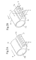
- FIG. 2-A shows a bracket material 14 for making the bracket 4.
- the bracket material 14 is made by extrusion molding light metal such as aluminum alloy, etc. or resin in the direction of an arrow E.
- the bracket material 14 is cut into the proper length to make a plurality of brackets.
- a cross section of the extrusion of the bracket material 14 is the same as a configuration of the front view ( FIG. 1-A ) of the bracket 4 and is integrally provided with a ring-shaped portion and a mounting projection 15 which extends radially outwardly from a portion of the ring-shaped portion.
- the extruding direction E is in coincidence with the direction of an imaginary center line of a bush mounting hole 14a formed in the bracket material 14.
- This mounting projection 15 is integrally formed with the bracket material 14 and extends continuously along the entire length of the bracket material 14 in the extruding direction E.
- a horizontal projection 17 which projects with height difference in the upward and downward direction with respect the mounting projection 15.
- the horizontal projection 17 is formed integral with the mounting projection 15 in the shape of projection extending continuously in the direction of extrusion.
- each of engaging projections 7 is formed on the horizontal projection 17 in an individually separate arrangement between the slits 18.
- the width (c) of each slit 18 is set to be substantially twice as large as the thickness (t) (see FIG. 1-B ) of a vertical wall of the arm portion 2.
- the width (a) in the vertical direction and the width (b) in the horizontal direction of each of the engaging projection are substantially identical with the width (a) in the vertical direction and the width (b) in the horizontal direction of the hollow portion 2c of the arm portion 2 (see FIG. 1-B and FIG. 2-B ), respectively.
- FIG. 3 shows an assembling state at the time of sub-assembling.
- the arm portion 2 is a square pipe made of the same kind of material as the bracket material 14 and is formed by regular-size cutting an extrusion molded arm material to the proper length previously.
- the engaging projection is fitted into an end 2a of the arm portion 2 Into an end 2a of the arm portion 2 the engaging projection is fitted.
- the engaging projection 7 is formed such as to be tightly fitted into a square hole 2c of the arm portion 2.
- one end 2a in the longitudinal direction of the arm portion 2 comes into contact with a mounting wall 15a (see FIG. 2 ) on an end of the mounting projection 15.
- the engaging projection 7 is fitted into the square hole 2c.
- the arm portion 2 is arranged in such a state that the extrusion direction of the arm portion 2 crosses at right angle the extrusion direction of the bracket material 14.
- each of the slits 18 since the width (c) of each of the slits 18 is twice as large as the thickness (t) of each of the vertical wall of the arm portion 2, the vertical walls of the neighboring arm portions 2 come into contact with each other and are tightly fitted into the slit 18. Therefore, a plurality of the arm portions 2 can be arranged without clearance in a horizontal row in the extrusion direction of the bracket material 14. Moreover, since each of the slits 18 functions as a clearance for the end 2a of the arm portion 2 when the end 2a is fitted onto the mounting projection 15, the end 2a of the arm potion 2 can be butted against the mounting wall 15a of the mounting projection 15 (see FIG. 6 ).
- the height H of the arm portion 2 is identical with the vertical width H of the mounting projection 15 (see FIG. 6 ), when the end 2a is butted against the mounting wall 15a, surfaces including the butted portion in the vicinity of the butted portion can form a flush tool traveling surface.
- the other end 2b of the arm portion 2 is engaged with the engaging projection 7 formed on other bracket material 14 so as to be sub-assembled in the similar way as on the side of the end 2a.
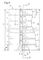
- FIG. 4 is a top plan view showing the arrangement in a horizontal row of the arm portions 2 in the sub-assembled state.
- a plurality of the arm portions 2 are arranged in a horizontal row without clearance in the extrusion direction of the bracket material 14.
- the width W2 of the entire arrangement in the case of arranging N pieces of the arm portion 2 in a horizontal row is W1 x N, which is set to be identical with the length L of the bracket material 14.
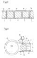
- FIG. 5 shows the engaged states between the engaging projections 7 and the ends of the arm portions 2 in a cross-section taken along line 5-5 of FIG. 4 .
- the neighboring arm portions 2 are arranged continuously without clearance in a horizontal row and upper and lower surfaces of the arm portions are made flush.
- FIG. 6 is a view showing a state of the friction stir welding.
- a probe 21 of a high speed rotation tool 20 is pressed on the butted portion 6 thereby to friction stir weld the materials on both sides of the butted portion 6 so as to be integrated.
- each surface of the mounting projection 15 and the end portions 2a on both sides of the butt portions 6 forms a tool traveling surface 22 and is flush without height difference, the friction stir welding with high reliability by the rotation tool 30 can be carried out.
- the butted portions 6 are formed continuously across the entire width of the arm portions 2 in a horizontal row, the entire arm potions 2 can be joined to and integrated with the mounting projection 15 in one process step by letting the rotation tool 20 travel along the joining line 16.
- the engaging projection 7 is press-fitted into the square hole 2c of the end 2c, even if the rotation tool 30 is pressed on the end 2a, the engaging projection 7 supports the end 2a from the inside thereof so that the end 2a can be prevented from denting downward.
- the stable friction stir welding by the rotation tool 30 can be carried out with high reliability.
- the whole of the bracket material 14 and the arm portions 2 sub-assembled as mentioned hereinabove is tuned over so that the back side is friction stir welded in one continuous process step in the similar way to the front side.
- FIG. 7 is a top plan view for explaining a friction stir welding process and cutting process.
- FIG. 8 shows the second embodiment wherein an arm portion 2 is not in the shape of pipe. Since the modification is made only with respect to the arm portion 2, like reference characters in the former embodiment are used commonly to like or corresponding parts and portions.
- FIG. 8-A shows an assembling operation of the arm portion 2. An end 2a of the arm portion 2 is butted against a mounting wall 15a of a mounting projection 15 in a bracket material 14 as shown in FIG. 2-B . Two or more arm portions 2 are arranged in a horizontal row with respect to the bracket material 14.
- the arm portion 2 is a longitudinally extending member having a substantially I-shaped cross section, formed by extrusion molding and regular-size cutting the arm material, and has a first wall 30, a second wall 31 and a third wall 32.
- the third wall 32 integrally connects in the vertical direction between the first wall 30 and the second wall31 which extend in a pair in parallel with each other on upper and lower horizontal planes.
- the thickness (c) of the third wall 32 is substantially the same as the width (c) of a slit 18.
- FIG. 8-B is a cross sectional view of neighboring two arm portions 2 in the direction crossing at a right angle the longitudinal direction of the arm portion 2.
- the thickness (t) of each of the first wall 30 and the second wall 31 is substantially identical with the space (t) between an engaging projection 7 and each of outer ends of upper and lower mounting walls 15a of a mounting projection 15 (see FIG. 8-A ).
- the first wall 30 and the second wall 31 each have protrusions 33, 34 each of which extend laterally from the third wall 32 in the direction crossing at a right angle the longitudinal direction of the arm portion 2.
- the tool traveling surface is formed in the shape of a straight line with respect to each of arm portions 2, and at the same time as shown in FIG. 4 , etc., the butted portions 6 extend continuously in a straight line. Therefore, when the tool travels on the tool traveling surface along the butted portions 6, the friction stir welding is carried out in one continuous process step. Then, since the first upper wall 30 and the second lower wall 31 which are being pressed by the tool each are supported by the engaging projection 7 to be prevented from deformation, it can meet the actually required conditions for friction stir welding, together with the flush tool traveling surface as mentioned above. In the case where the extrusion material of substantially I-shaped cross section of a relatively moderate price is employed, the efficient manufacture using the friction stir welding also may be carried out.
- FIGs. 10-13 show a third embodiment.
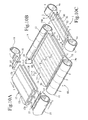
- FIG. 10 is a view for schematically explaining an entire method of manufacturing a link rod 1.
- a view A shows a process of butting each end of left and right mounting projections 15 provided on left and right bracket materials 14 against both ends 12a, 12b of an arm material 12, after extrusion molding the left and the right bracket materials 14 and the arm material 12.
- the bracket material 14 is substantially the same as the one shown in each of the above embodiments.
- 14a denotes an integrally formed bush mounting hole.
- a view B shows a process of friction stir welding.
- the left and the right bracket materials 14 and the arm material 12 are sub-assembled to form a sub-assembled body 60 in such a manner that the mounting projections 15 of the left and the right bracket materials 14 are butted against both ends 12a, 12b of the arm material 12 while having engaging projections7 fitted into both ends 12a, 12b of the arm material 12.
- the friction stir welding is carried out by letting a rotation tool 30 travel along a butt line 66 between the arm material 12 and the mounting projections 15 so that the arm material 12 and the mounting projections 15 are joined and integrated together.
- a link rod 1 as shown in a view C is obtained.
- the view C shows in perspective the link rod 1 which is separated and finished. 4a denotes a bush mounting hole.
- This link rod 1 is the same as the one shown in FIG. 8 . Therefore, the reference characters in the second embodiment are commonly used with respect to the link rod 1 as a product shown in the view C.
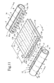
- FIG. 11 is a view showing details of the process of FIG. 10-A .
- the arm material 12 is obtained by extrusion molding light metal such as aluminum ally, etc. or resin in the direction of the arrow E such that the width of the extrusion corresponds to the one obtained by arranging in a horizontal row a plurality of arm portions 2 (in this example, 5 pieces) as shown in FIG. 10 and by regular-size cutting the extrusion to the length L2 of the arm portion 2.
- the width W3 of the extrusion is W1 x 5 (pieces) wherein W1 is the width of a product, and it corresponds to W2 of FIG. 4 .
- the arm material 12 has a first wall 12c, a second wall 12d and third walls 12e of substantially rib shape which cross at right angles the first and second walls 12c, 12d.
- the first and second walls 12c, 12d extend in parallel with each other while having the thirds wall 12e arranged between them.
- the third walls 12e extend along the entire length in the direction of extrusion and are formed with five pieces at regular intervals in the width direction of extrusion. These three walls are formed integral with each other. Between the neighboring third walls 12e there are formed hollow portions 12f which pass through the arm material 12 in the direction of extrusion. On each end in the width direction of extrusion there is provided a groove 12g which is opened laterally.
- the materials 14 for bracket are obtained by being extrusion molded and then by being regular-size cut to the length W1 x 5, wherein W1 is the width of a product. This length is equal to L of FIG. 4 and substantially identical to the width W3 of extrusion of the arm material 12.
- a horizontal projection 17 (see FIG. 10-A ) which projects from the mounting projection 15 and extends continuously in the direction of extrusion.
- slits 18 are formed at predetermined intervals in the extrusion direction by cutting or the like after the regular-size cutting of the bracket material 14 following the extrusion molding, so as to form engaging projections 7.
- the bracket material 14 after forming the slits 18 is identical with the one shown in FIG. 8-A , and the slits 18 each have the width allowing the third wall 12e to be fitted.
- the engaging projections 7 are separated from the neighboring ones by the slits 18 and each formed to be tightly fitted into the hollow portions 12f and the end grooves 12g.
- the arm material 12 and the bracket materials 14 are butted each other such that the extrusion direction E of the arm material 12 crosses at a right angle the extrusion direction E of the bracket materials 14. Then, The third walls 12e of the arm material 12 are fitted into the slits 18 of the bracket material 14. At the same time the engaging projections 7 of the bracket material 14 are engaged with the hollow portions 12f of the end grooves 12g of the arm material 12 . At this time. the mounting walls 15a of the mounting projections 15 butt against end surfaces 12a, 12b on both ends of the arm material 12, as in the first embodiment.
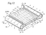
- FIG. 12 is a view showing in enlarged scale the process B shown in FIG. 10 . Since this sub-assembled body 60 has the friction stir welding line (the butt line) 66 which is formed in the shape of continuous straight line, the friction stir welding can be smoothly carried out on this line in one continuous process step. The process of friction stir welding is performed in a similar manner as in FIG. 6 . Thereafter, the entire length of the sub-assembled body 60 is cut in the extrusion direction of the arm material 12 along the cutting lines F passing the intermediate point of the neighboring third walls 12e, 12e with a proper cutter such as a band saw or the like so as to separate the neighboring link rods 1 (see FIG. 10 ) from each other. The cutting length at this time is L1 (the length of the bracket 4) x 2 + L2 (the length of the arm portion 2).
- FIG. 13 is a view showing the end of the arm material 12 viewed from the direction of extrusion.
- Each of the engaging projections 7 is engaged between the first wall 12c and the second wall 12d.
- Each of the hollow portions 12f has a horizontally extending rectangular shape in a state shown in the drawing.
- F is the cutting line. After the process step of friction stir welding, the intermediate point between the neighboring third walls 12e is cut along the cutting line F.
- bracket materials 14 and the arm material 12 for a plurality of link rods by extrusion molding. Also, since it is possible to carry out manufacture using only these three members, the treatment and the positioning can be facilitated. Moreover, the entire surfaces in the vicinity of the butted portions 6 along the friction stir welding line 66 are made flush, so that it is easy to form the continuous flat tool traveling plane so as to easily carry the friction stir welding operation. Further, in the process step of friction stir welding the same effects as in each of the preceding embodiments can be obtained.
- the arm portion since for the arm portion it is required to provide a first wall 30, a second wall 31 and a third wall 32 and to form a space between the first wall 30 and the second wall 31, the arm portion is not limited to a pipe member but may be formed by a member of I-shaped cross section, H-shaped cross section, etc.
- An arm member provided with two or more third walls 32 and the protrusions as mentioned hereinbefore may be employed. Such arm members may be easily and cheaply formed by extrusion molding.
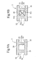
- FIG. 9-A and B are schematic cross-sectional views of the arm portions 2.
- A is an example of the arm portion 2 having two or more third walls 32a, 32a.
- B is an example of the arm portion 2 having diagonally crossing walls 32b, 23c in addition to the third walls 32a, 32a.
- the link rod can be applied to various devices for vehicle such as a suspension, an engine mount, etc.
- an extrusion molded bracket material (14) is formed to have the length allowing N pieces of the arm portions to be arranged in a horizontal row.
- Engaging projections (7) provided on the bracket material (14) are engaged with ends of the arm portions (2). Then, the ends of the arm portions (2) are butted against mounting walls (15a) provided on a mounting projection (15) of the bracket material 14. N pieces of the arm portions (2) are arranged without clearance in a horizontal row with respect to the bracket material (14) to form butted portions in the shape of a continuous straight line. The friction stir welding is carried out along the butted portions. Then, the bracket material (14) is cut into the width of the bracket (4).
- the engaging projections (7) are formed by forming slits (18) at given intervals on a horizontal projection (17) extrusion molded integrally with the bracket material (14).
Landscapes
- Engineering & Computer Science (AREA)
- Mechanical Engineering (AREA)
- Vehicle Body Suspensions (AREA)
- Pressure Welding/Diffusion-Bonding (AREA)
Priority Applications (1)
| Application Number | Priority Date | Filing Date | Title |
|---|---|---|---|
| EP07007083A EP1977849A1 (fr) | 2007-04-04 | 2007-04-04 | Procédé de fabrication de tige de liaison par soudage par friction agitation avec formage de fentes à des intervalles donnés sur un bossage de la fixation |
Applications Claiming Priority (1)
| Application Number | Priority Date | Filing Date | Title |
|---|---|---|---|
| EP07007083A EP1977849A1 (fr) | 2007-04-04 | 2007-04-04 | Procédé de fabrication de tige de liaison par soudage par friction agitation avec formage de fentes à des intervalles donnés sur un bossage de la fixation |
Publications (1)
| Publication Number | Publication Date |
|---|---|
| EP1977849A1 true EP1977849A1 (fr) | 2008-10-08 |
Family
ID=38445666
Family Applications (1)
| Application Number | Title | Priority Date | Filing Date |
|---|---|---|---|
| EP07007083A Withdrawn EP1977849A1 (fr) | 2007-04-04 | 2007-04-04 | Procédé de fabrication de tige de liaison par soudage par friction agitation avec formage de fentes à des intervalles donnés sur un bossage de la fixation |
Country Status (1)
| Country | Link |
|---|---|
| EP (1) | EP1977849A1 (fr) |
Cited By (3)
| Publication number | Priority date | Publication date | Assignee | Title |
|---|---|---|---|---|
| EP2995481A1 (fr) * | 2014-09-12 | 2016-03-16 | Edai Technical Unit, A.I.E. | Procédé d'obtention d'un bras de suspensions à liaisons multiples de véhicules automobiles et bras de suspension |
| EP2987584A4 (fr) * | 2014-02-14 | 2017-01-04 | Isel Co., Ltd | Procédé de fabrication de corps structurel, corps structurel et échangeur de chaleur |
| WO2018197131A1 (fr) * | 2017-04-24 | 2018-11-01 | Zf Friedrichshafen Ag | Bras oscillant d'essieu |
Citations (5)
| Publication number | Priority date | Publication date | Assignee | Title |
|---|---|---|---|---|
| JPH11101285A (ja) * | 1997-09-29 | 1999-04-13 | Tokai Rubber Ind Ltd | ブッシュ装着用部材の製造方法 |
| JPH1199415A (ja) * | 1997-09-29 | 1999-04-13 | Unipres Corp | 溶接品の製造方法及びリンク材 |
| JP2001206031A (ja) * | 2000-01-21 | 2001-07-31 | Tokai Rubber Ind Ltd | アーム用部材 |
| JP2006136943A (ja) * | 2004-10-14 | 2006-06-01 | Yamashita Rubber Co Ltd | リンクロッドの製法 |
| JP2006136942A (ja) * | 2004-10-14 | 2006-06-01 | Yamashita Rubber Co Ltd | リンクロッドの製法 |
-
2007
- 2007-04-04 EP EP07007083A patent/EP1977849A1/fr not_active Withdrawn
Patent Citations (5)
| Publication number | Priority date | Publication date | Assignee | Title |
|---|---|---|---|---|
| JPH11101285A (ja) * | 1997-09-29 | 1999-04-13 | Tokai Rubber Ind Ltd | ブッシュ装着用部材の製造方法 |
| JPH1199415A (ja) * | 1997-09-29 | 1999-04-13 | Unipres Corp | 溶接品の製造方法及びリンク材 |
| JP2001206031A (ja) * | 2000-01-21 | 2001-07-31 | Tokai Rubber Ind Ltd | アーム用部材 |
| JP2006136943A (ja) * | 2004-10-14 | 2006-06-01 | Yamashita Rubber Co Ltd | リンクロッドの製法 |
| JP2006136942A (ja) * | 2004-10-14 | 2006-06-01 | Yamashita Rubber Co Ltd | リンクロッドの製法 |
Cited By (4)
| Publication number | Priority date | Publication date | Assignee | Title |
|---|---|---|---|---|
| EP2987584A4 (fr) * | 2014-02-14 | 2017-01-04 | Isel Co., Ltd | Procédé de fabrication de corps structurel, corps structurel et échangeur de chaleur |
| EP2995481A1 (fr) * | 2014-09-12 | 2016-03-16 | Edai Technical Unit, A.I.E. | Procédé d'obtention d'un bras de suspensions à liaisons multiples de véhicules automobiles et bras de suspension |
| US9636961B2 (en) | 2014-09-12 | 2017-05-02 | Edai Technical Unit, A.I.E. | Method for obtaining an arm for multi-link suspensions of automotive vehicles and a suspension arm |
| WO2018197131A1 (fr) * | 2017-04-24 | 2018-11-01 | Zf Friedrichshafen Ag | Bras oscillant d'essieu |
Similar Documents
| Publication | Publication Date | Title |
|---|---|---|
| US7832102B2 (en) | Link rod manufacturing method | |
| US20080235946A1 (en) | Link rod manufacturing method | |
| US10472016B2 (en) | Bicycle frame and manufacturing method thereof | |
| CN102328695B (zh) | 尤其位于汽车车身前端上的装置 | |
| US5767476A (en) | Manufacturing method for automotive frame | |
| WO2015045537A1 (fr) | Filière d'extrusion pour le formage de matériau creux | |
| CN101279402A (zh) | 连杆的制法 | |
| US20030080589A1 (en) | Multi-section support rail apparatus and method of making | |
| KR101447344B1 (ko) | 구조 부재 | |
| US20050013954A1 (en) | Tailored tubular blanks and a method for the production thereof | |
| JPH11101286A (ja) | ブッシュ装着用部材の製造方法 | |
| JP5172502B2 (ja) | 車体フレームの接続構造及び成形方法 | |
| EP1977848A1 (fr) | Procédé de fabrication d' une bielle de liaison | |
| US20070245798A1 (en) | Integral Axle Housing for Vehicle and Method of Manufacture the Same | |
| WO2012169525A1 (fr) | Élément de poutre | |
| JP2006136942A (ja) | リンクロッドの製法 | |
| WO2021054032A1 (fr) | Procédé de jonction et corps joint | |
| JPH1199415A (ja) | 溶接品の製造方法及びリンク材 | |
| JP2005519771A (ja) | 軽量構成要素ならびにその製造方法 | |
| JP2006136943A (ja) | リンクロッドの製法 | |
| JP4555658B2 (ja) | リンクの製法 | |
| JP2003211326A (ja) | 金属部品の製造方法および金属部品 | |
| JP4014258B2 (ja) | 金属製パイプ及びその製造方法 | |
| CN110001699A (zh) | 轨道车辆转向架 | |
| JP2006136941A (ja) | リンク用ロッドの製法 |
Legal Events
| Date | Code | Title | Description |
|---|---|---|---|
| PUAI | Public reference made under article 153(3) epc to a published international application that has entered the european phase |
Free format text: ORIGINAL CODE: 0009012 |
|
| AK | Designated contracting states |
Kind code of ref document: A1 Designated state(s): AT BE BG CH CY CZ DE DK EE ES FI FR GB GR HU IE IS IT LI LT LU LV MC MT NL PL PT RO SE SI SK TR |
|
| AX | Request for extension of the european patent |
Extension state: AL BA HR MK RS |
|
| RAP1 | Party data changed (applicant data changed or rights of an application transferred) |
Owner name: YAMASHITA RUBBER KABUSHIKI KAISHA |
|
| AKX | Designation fees paid |
Designated state(s): DE ES FR GB IT |
|
| STAA | Information on the status of an ep patent application or granted ep patent |
Free format text: STATUS: THE APPLICATION IS DEEMED TO BE WITHDRAWN |
|
| 18D | Application deemed to be withdrawn |
Effective date: 20090409 |