EP1978135A2 - Appareil de traitement d'électrolyse, support de plaque d'impression planographique, plaque d'impression planographique, et processus de traitement d'électrolyse - Google Patents
Appareil de traitement d'électrolyse, support de plaque d'impression planographique, plaque d'impression planographique, et processus de traitement d'électrolyse Download PDFInfo
- Publication number
- EP1978135A2 EP1978135A2 EP08006062A EP08006062A EP1978135A2 EP 1978135 A2 EP1978135 A2 EP 1978135A2 EP 08006062 A EP08006062 A EP 08006062A EP 08006062 A EP08006062 A EP 08006062A EP 1978135 A2 EP1978135 A2 EP 1978135A2
- Authority
- EP
- European Patent Office
- Prior art keywords
- electrolysis
- current density
- metal strip
- electrode
- treatment apparatus
- Prior art date
- Legal status (The legal status is an assumption and is not a legal conclusion. Google has not performed a legal analysis and makes no representation as to the accuracy of the status listed.)
- Withdrawn
Links
- 238000005868 electrolysis reaction Methods 0.000 title claims abstract description 254
- 238000011282 treatment Methods 0.000 title claims abstract description 147
- 238000000034 method Methods 0.000 title claims description 14
- 229910052751 metal Inorganic materials 0.000 claims abstract description 77
- 239000002184 metal Substances 0.000 claims abstract description 77
- 230000002378 acidificating effect Effects 0.000 claims abstract description 17
- 239000008151 electrolyte solution Substances 0.000 claims abstract description 13
- 229910052782 aluminium Inorganic materials 0.000 claims description 61
- XAGFODPZIPBFFR-UHFFFAOYSA-N aluminium Chemical compound [Al] XAGFODPZIPBFFR-UHFFFAOYSA-N 0.000 claims description 60
- 239000004411 aluminium Substances 0.000 claims description 59
- 238000007788 roughening Methods 0.000 claims description 34
- 238000011144 upstream manufacturing Methods 0.000 claims description 24
- 229940021013 electrolyte solution Drugs 0.000 abstract 1
- 230000007547 defect Effects 0.000 description 14
- 238000006243 chemical reaction Methods 0.000 description 12
- 230000000052 comparative effect Effects 0.000 description 10
- 238000010586 diagram Methods 0.000 description 4
- 239000003792 electrolyte Substances 0.000 description 4
- 238000009413 insulation Methods 0.000 description 4
- 238000002048 anodisation reaction Methods 0.000 description 3
- VEXZGXHMUGYJMC-UHFFFAOYSA-N Hydrochloric acid Chemical compound Cl VEXZGXHMUGYJMC-UHFFFAOYSA-N 0.000 description 2
- NBIIXXVUZAFLBC-UHFFFAOYSA-N Phosphoric acid Chemical compound OP(O)(O)=O NBIIXXVUZAFLBC-UHFFFAOYSA-N 0.000 description 2
- QAOWNCQODCNURD-UHFFFAOYSA-N Sulfuric acid Chemical compound OS(O)(=O)=O QAOWNCQODCNURD-UHFFFAOYSA-N 0.000 description 2
- 230000006698 induction Effects 0.000 description 2
- 238000012986 modification Methods 0.000 description 2
- 230000004048 modification Effects 0.000 description 2
- BASFCYQUMIYNBI-UHFFFAOYSA-N platinum Chemical compound [Pt] BASFCYQUMIYNBI-UHFFFAOYSA-N 0.000 description 2
- 229910000838 Al alloy Inorganic materials 0.000 description 1
- LSNNMFCWUKXFEE-UHFFFAOYSA-M Bisulfite Chemical compound OS([O-])=O LSNNMFCWUKXFEE-UHFFFAOYSA-M 0.000 description 1
- OKTJSMMVPCPJKN-UHFFFAOYSA-N Carbon Chemical compound [C] OKTJSMMVPCPJKN-UHFFFAOYSA-N 0.000 description 1
- XEEYBQQBJWHFJM-UHFFFAOYSA-N Iron Chemical group [Fe] XEEYBQQBJWHFJM-UHFFFAOYSA-N 0.000 description 1
- GRYLNZFGIOXLOG-UHFFFAOYSA-N Nitric acid Chemical compound O[N+]([O-])=O GRYLNZFGIOXLOG-UHFFFAOYSA-N 0.000 description 1
- 239000004677 Nylon Substances 0.000 description 1
- BZHJMEDXRYGGRV-UHFFFAOYSA-N Vinyl chloride Chemical compound ClC=C BZHJMEDXRYGGRV-UHFFFAOYSA-N 0.000 description 1
- WNROFYMDJYEPJX-UHFFFAOYSA-K aluminium hydroxide Chemical group [OH-].[OH-].[OH-].[Al+3] WNROFYMDJYEPJX-UHFFFAOYSA-K 0.000 description 1
- 229910021502 aluminium hydroxide Inorganic materials 0.000 description 1
- -1 aluminium ions Chemical class 0.000 description 1
- 229910000147 aluminium phosphate Inorganic materials 0.000 description 1
- 229910052799 carbon Inorganic materials 0.000 description 1
- 230000007797 corrosion Effects 0.000 description 1
- 238000005260 corrosion Methods 0.000 description 1
- 230000007423 decrease Effects 0.000 description 1
- 238000005530 etching Methods 0.000 description 1
- 238000011156 evaluation Methods 0.000 description 1
- 239000004744 fabric Substances 0.000 description 1
- 239000000835 fiber Substances 0.000 description 1
- 229910002804 graphite Inorganic materials 0.000 description 1
- 239000010439 graphite Substances 0.000 description 1
- 230000001939 inductive effect Effects 0.000 description 1
- 229910017604 nitric acid Inorganic materials 0.000 description 1
- 229920001778 nylon Polymers 0.000 description 1
- 229910052697 platinum Inorganic materials 0.000 description 1
- 239000011347 resin Substances 0.000 description 1
- 229920005989 resin Polymers 0.000 description 1
- 230000000717 retained effect Effects 0.000 description 1
- 230000000007 visual effect Effects 0.000 description 1
- 229910000859 α-Fe Inorganic materials 0.000 description 1
Images


Classifications
-
- C—CHEMISTRY; METALLURGY
- C25—ELECTROLYTIC OR ELECTROPHORETIC PROCESSES; APPARATUS THEREFOR
- C25D—PROCESSES FOR THE ELECTROLYTIC OR ELECTROPHORETIC PRODUCTION OF COATINGS; ELECTROFORMING; APPARATUS THEREFOR
- C25D7/00—Electroplating characterised by the article coated
- C25D7/06—Wires; Strips; Foils
- C25D7/0614—Strips or foils
-
- B—PERFORMING OPERATIONS; TRANSPORTING
- B41—PRINTING; LINING MACHINES; TYPEWRITERS; STAMPS
- B41N—PRINTING PLATES OR FOILS; MATERIALS FOR SURFACES USED IN PRINTING MACHINES FOR PRINTING, INKING, DAMPING, OR THE LIKE; PREPARING SUCH SURFACES FOR USE AND CONSERVING THEM
- B41N3/00—Preparing for use and conserving printing surfaces
- B41N3/03—Chemical or electrical pretreatment
- B41N3/034—Chemical or electrical pretreatment characterised by the electrochemical treatment of the aluminum support, e.g. anodisation, electro-graining; Sealing of the anodised layer; Treatment of the anodic layer with inorganic compounds; Colouring of the anodic layer
-
- C—CHEMISTRY; METALLURGY
- C25—ELECTROLYTIC OR ELECTROPHORETIC PROCESSES; APPARATUS THEREFOR
- C25D—PROCESSES FOR THE ELECTROLYTIC OR ELECTROPHORETIC PRODUCTION OF COATINGS; ELECTROFORMING; APPARATUS THEREFOR
- C25D11/00—Electrolytic coating by surface reaction, i.e. forming conversion layers
- C25D11/02—Anodisation
- C25D11/04—Anodisation of aluminium or alloys based thereon
- C25D11/12—Anodising more than once, e.g. in different baths
-
- C—CHEMISTRY; METALLURGY
- C25—ELECTROLYTIC OR ELECTROPHORETIC PROCESSES; APPARATUS THEREFOR
- C25D—PROCESSES FOR THE ELECTROLYTIC OR ELECTROPHORETIC PRODUCTION OF COATINGS; ELECTROFORMING; APPARATUS THEREFOR
- C25D5/00—Electroplating characterised by the process; Pretreatment or after-treatment of workpieces
- C25D5/18—Electroplating using modulated, pulsed or reversing current
-
- C—CHEMISTRY; METALLURGY
- C25—ELECTROLYTIC OR ELECTROPHORETIC PROCESSES; APPARATUS THEREFOR
- C25D—PROCESSES FOR THE ELECTROLYTIC OR ELECTROPHORETIC PRODUCTION OF COATINGS; ELECTROFORMING; APPARATUS THEREFOR
- C25D5/00—Electroplating characterised by the process; Pretreatment or after-treatment of workpieces
- C25D5/60—Electroplating characterised by the structure or texture of the layers
- C25D5/605—Surface topography of the layers, e.g. rough, dendritic or nodular layers
-
- C—CHEMISTRY; METALLURGY
- C25—ELECTROLYTIC OR ELECTROPHORETIC PROCESSES; APPARATUS THEREFOR
- C25F—PROCESSES FOR THE ELECTROLYTIC REMOVAL OF MATERIALS FROM OBJECTS; APPARATUS THEREFOR
- C25F3/00—Electrolytic etching or polishing
- C25F3/02—Etching
- C25F3/04—Etching of light metals
Definitions
- the present invention relates to an electrolysis treatment apparatus, a support for a planographic printing plate, a planographic printing plate, and an electrolysis treatment process.
- the present invention relates to an electrolysis treatment apparatus and an electrolysis treatment process, and particularly relates to an electrolysis treatment apparatus and electrolysis treatment process capable of effectively suppressing occurrences of chatter marks on the surface of a metal strip even when the electrolysis treatment is performed on the metallic plate continuously under a high current density and at a high conveyance speed.
- a planographic printing original plate which is an original plate for a planographic printing plate, is generally manufactured by a procedure in which: a surface of a plate of pure aluminium or an aluminium alloy (below referred to as 'aluminium or the like') is roughened; then an anodization treatment is performed so that an anodization film is formed on the roughened surface, thus providing a support for the planographic printing plate; and a photosensitive or heat-sensitive platemaking layer is formed on the surface of the planographic printing plate support on which the anodization film has been formed.
- a printing image of text, a picture or the like is printed into the plate-making layer of the planographic printing plate and developed, and thus a planographic printing plate is produced.
- the aluminium plate is surface-roughened by: a mechanical surface-roughening treatment with a brush roller featuring fibers of nylon or the like, an abrasive roller with a surface formed with an abrasive cloth, or the like; an etching treatment wherein a surface of the aluminium plate is chemically roughened in an alkaline bath; an electrolytic surface-roughening treatment wherein electrolytic surface-roughening is performed with the aluminium plate serving as one electrode; or the like (see Japanese Patent Application Laid-Open ( JP-A) Nos. 60-067700 and 1-230800 ).
- the electrolytic surface-roughening is usually performed by applying an alternating current such as a sinusoidal current, a rectangular wave current, a trapezoid wave current or the like to the aluminium plate in an acidic electrolyte solution.
- an alternating current such as a sinusoidal current, a rectangular wave current, a trapezoid wave current or the like
- positive voltage and negative voltage are alternatingly applied to the aluminium plate at an entrance of an electrolysis cell.
- a cathode reaction takes place at the aluminium plate when a positive voltage is applied, and an anode reaction takes place when a negative voltage is applied.
- an oxide film of which principal component is aluminium hydroxide is formed, and at the time of the anode reaction, the oxide film is electrolyzed and honeycomb-like small holes called pits are formed.
- the cathode reaction occurs first at the aluminium plate that is passing through the electrolysis cell, and when a negative voltage is being applied, the anode reaction occurs first.
- surface conditions of the aluminium plate vary in accordance with the polarity of the voltage that is applied at the entrance of the electrolysis cell, and surface quality defects in the form of stripes extending in a width direction of the aluminium plate, that is, chatter marks, takes place.
- chatter marks is especially noticeable when the electrolytic-roughening treatment is implemented at a high conveyance speed and under a high current density.
- an electrolysis treatment apparatus in which a soft zone which applies low current density treatment is provided at an entry aperture region of an electrolysis cell (refer to Japanese Patent Application Laid-Open(JP-A) No. 60-067700 ); an electrolysis treatment apparatus in which low current density zones are provided at a leading end and trailing end of each electrode in an electrolysis cell, and a region of the rest of the electrode is a constant current density zone (refer to Japanese Patent Application Laid-Open(JP-A) No.
- an electrolysis treatment apparatus in which the electrolysis treatment apparatus is provided with a soft start region at an entry aperture region of an electrolysis cell, and a length of the soft start region is determined so as to satisfy a particular relationship with a current density of the soft start region, a section length and a metal strip conveyance speed (see JP-A No. 2003-003299 ).
- the present invention has been made in order to solve the problem described above, and a first aspect for solving the problem relates to an electrolysis treatment apparatus that performs electrolysis treatment on a metal strip running in a predetermined direction
- the electrolysis treatment apparatus comprising: a plurality of electrolysis cells that perform electrolysis treatment continuously with alternating current in an acidic electrolyte solution, the electrolysis cells being arranged in a row along the running direction of the metal strip, and current density of the alternating current in the plurality of electrolysis cells being set so as to be lowest in the electrolysis cell that is disposed furthest downstream with respect to the running direction of the metal strip; in each of the electrolysis cells, one or more electrodes being disposed so as to face a running path of the metal strip, alternating current being applied to the electrodes, and a soft start portion being provided at an entry region of each electrode from which entry region the metal strip is fed in; in the electrolysis cell(s) except the most downstream electrolysis cell, a low current density zone being provided at an exit region from which the metal strip is
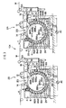
- an electrolytic surface-roughening treatment apparatus 100 relating to a first embodiment is provided with an electrolysis cell 2A that is disposed at an upstream side with respect to a conveyance direction t of an aluminium strip W and an electrolysis cell 2B that is disposed at the downstream side of the electrolysis cell 2A with respect to the conveyance direction t.
- Each of the electrolysis cells 2A and 2B is equipped with an electrolysis cell main body 4 and a feeding roller 6.
- the electrolysis cell main body 4 retains an acidic electrolyte solution.
- the feeding roller 6 is arranged in a horizontal direction inside the electrolysis cell main body 4, and turns around an axis thereof in the clockwise direction of Fig. 1 to feed the aluminium strip W along the conveyance direction t.
- An inner wall face of the electrolysis cell main body 4 is formed in a substantially cylindrical shape, and half-cylinder-form electrodes 8A and 8B are provided on the inner wall surface so as to encircle the feeding roller 6.
- the electrodes 8A and 8B are divided-type electrodes which are divided along the circumferential direction into pluralities of small electrodes 82A and 82B, respectively. Insulation layers 84A and 84B are interposed between the small electrodes 82A and 82B, respectively.
- the small electrodes 82A and 82B can be formed using, for example, graphite, a metal or the like, and the insulation layers 84A and 84B can be formed of, for example, a vinyl chloride resin or the like.
- Thicknesses of the insulation layers 84A and 84B are preferably 1 to 10 mm.
- the small electrodes 82A and 82B are respectively connected to an Alternating current power supply AC.
- the small electrodes 82A and 82B and the insulation layers 84A and 84B are all retained by an insulating electrode holder 86, and thus the electrodes 8A and 8B are formed.
- the Alternating current power supply AC applies alternating currents to the electrodes 8A and 8B.
- the Alternating current power supply AC may be a sinusoidal wave generation circuit, which generates a sinusoidal wave by adjusting voltage and current of a commercial alternating current by using an inductive voltage regulator and a transformer, a thyristor circuit, which generates a trapezoid wave current or a rectangular wave current from a direct current that is obtained by a method such as rectifying a commercial alternating current, or the like.
- an aperture portion 20 for feeding in and out the aluminium strip W is formed.
- Nitric acid, sulfuric acid, hydrochloric acid, phosphoric acid and sulfonic acid are examples of an acidic electrolyte that can be incorporated into the acidic electrolyte solution. Only one kind of acidic electrolyte or two or more kinds of acidic electrolytes may be incorporated. Besides the acidic electrolyte, aluminium ions and the like may be incorporated in the acidic electrolyte solution.
- a group of upstream side guide rollers 12 and a downstream side guide roller 14 are disposed above the electrolysis cell 2A or 2B in the vicinity of the aperture portion 20.
- the upstream side guide rollers 12 guide the aluminium strip W into the electrolysis cell 2A or 2B.
- the downstream side guide roller 14 guides the aluminium strip W that has been subjected to electrolytic surface-roughening treatment in the electrolysis cell 2A or 2B toward the outside thereof.
- an auxiliary electrolysis cell 16 is provided adjacent to the upstream side of the electrolysis cell main body 4.
- the auxiliary electrolysis cell 16 is shallower than the electrolysis cell main body 4, and a floor 16A is formed as a horizontal surface.
- a plate-form auxiliary electrode 18 is disposed above the floor 16A.
- the auxiliary electrode 18 is preferably formed of a highly corrosion-resistant metal such as platinum or the like, or a ferrite or the like, and can be rod-shaped.
- the auxiliary electrode 18 is connected to the alternating current power supply AC at a side to which the electrode 8B is connected in parallel with the electrode 8B. Between the auxiliary electrode 18 and the Alternating current power supply AC, a diode 22 is connected such that electric current flow in the direction from the Alternating current power supply AC to the auxiliary electrode 18.
- soft start portions 88A and 88B are provided at upstream side end portions of the electrodes 8A and 8B, respectively.
- the soft start portions 88A and 88B include, respectively, asymptotic portions 88A 2 and 88B 2 and, located at the downstream sides of the asymptotic portions, inductance inclusion portions 88A 4 and 88B 4 .
- the asymptotic portions 88A 2 and 88B 2 are sections that are asymptotic to the surface of the feeding roller 6, along the conveyance direction t.
- the inductance inclusion portions 88A 4 and 88B 4 are sections at which inductance coils 24 are included between the small electrodes 82A or 82B and the Alternating current power supply AC.
- a low current density zone 87A is formed, located at the downstream side of the conveyance direction t, that is, at the side of feeding out of the aluminium strip W.
- inductance coils 25 are included between the small electrodes 82A of the electrode 8A and the Alternating current power supply AC.
- the low current density zone 87A is preferably formed such that a treatment time duration of the aluminium strip W thereat is at least 6% of an overall treatment time duration of the aluminium strip W in the electrolysis cell 2A.
- a current density of the alternating current applied to the electrodes 8A and 8B in the electrolysis cell 2A is higher than a current density of the alternating current applied to the electrodes 8A and 8B in the electrolysis cell 2B, with the former being preferably 1.2 to 2 times higher than the latter.
- the current densities in the electrolysis cells 2A and 2B are defined as average current densities, including the soft start portions 88A and 88B and the low current density zone 87A.
- the current density of the alternating current applied to the electrodes 8A and 8B in the electrolysis cell 2B is preferably in a range from 15 to 30 A/dm 2 .
- Inductances of the inductance coils 25 are specified such that a ratio d/D between a current density d (A/dm 2 ) at the low current density zone 87A and a current density D (A/dm 2 ) of other regions will be 0.75 or less, preferably in the range from 0.3 to 0.75.
- resistors could be used in place of the inductance coils 24 and 25 at the soft start portions 88A and 88B and the low current density zone 87A, and that otherwise the soft start portions 88A and 88B and the low current density zone 87A are connected to a different power supply that a power supply to which the rest portions of the electrodes 8A and 8B are connected.
- the aluminium strip W is guided to the electrolysis cell 2A from the right side of Fig. 1 , and is first fed into the auxiliary electrolysis cell 16 and subjected to an anode reaction. Then, the aluminium strip W is fed into the electrolysis cell main body 4 by the upstream side guide rollers 12.
- the aluminium strip W is conveyed along the conveyance direction t inside the electrolysis cell main body 4 by the feeding roller 6, and first passes through the soft start portion 88B.
- the current density is much smaller than a current density MC A of the alternating current that is applied to the electrolysis cell 2A.
- the current density increases as the aluminium strip W moves to the downstream side, and is equal to the current density MC A at a downstream side end portion, that is, an end point of the soft start portion 88B.
- the aluminium strip W After the aluminium strip W has passed through the soft start portion 88B, the aluminium strip W is conveyed along the electrode 8B of the electrolysis cell main body 4, and a surface at the side of the aluminium strip W that opposes the electrode 8B is subjected to anode and cathode reactions by the alternating current that is applied from the Alternating current power supply AC to the electrode 8B.
- the aluminium strip W that has passed along the electrode 8B then passes through the soft start portion 88A formed in the electrolysis cell main body 4.
- the current density is much smaller at a start point than the current density MC A , increases as the aluminium strip W moves to the downstream side, and is equal to the current density MC A at an end point.
- the aluminium strip W After the aluminium strip W has passed through the soft start portion 88A, similarly, the aluminium strip W is conveyed along the electrode 8A, the surface of the side that opposes the electrode 8A is subjected to anode and cathode reactions by the alternating current that is applied from the Alternating current power supply AC to the electrode 8A, and honeycomb pits are formed over the whole surface. Finally, the aluminium strip W passes through the low current density zone 87A.
- the aluminium strip W that has been fed out from the electrolysis cell 2A is then guided to the electrolysis cell 2B.
- the aluminium strip W that has been guided to the electrolysis cell 2B is first fed into the auxiliary electrolysis cell 16 and subjected to the anode reaction.
- the aluminium strip W is then fed into the electrolysis cell main body 4 by the upstream side guide rollers 12.
- current densities are smaller than a current density MC B of the electrolysis cell 2B at the start points of the soft start portions 88A and 88B and are equal to the current density MC B at the end points of the soft start portions 88A and 88B.
- the electrolytic surface-roughening treatment is performed with the current density MC B at downstream sides from the soft start portions 88A and 88B.
- the current density MC B of the electrolysis cell 2B is smaller than the current density MC A of the electrolysis cell 2A, specifically being in a range from MC A /1.2 to MC A /2.
- the aluminium strip W that has passed through the electrolysis cell main body 4 of the electrolysis cell 2B is fed out from the electrolysis cell main body 4 by the downstream side guide roller 14.
- the alternating currents applied to the electrolysis cells 2A and 2B may be trapezoid wave currents, or alternatively, sinusoidal wave currents or rectangular wave currents. Furthermore, currents in which a direct current is superimposed with a trapezoid current, a sinusoidal wave current or a rectangular wave current are to be included.
- the electrolytic surface-roughening treatment is implemented with the current density in the electrolysis cell 2B disposed at the furthest downstream side being 1/1.2 to 1/2 of the current density in the upstream side electrolysis cell 2A. Therefore, the surface quality defects described by the phrase "problem to be solved by the invention" are particularly unlikely to occur.
- the soft start portions 88A and 88B and the low current density zone 87A are provided in the electrolysis cell main bodies 4 of the electrolysis cell 2A. Therefore, in both of the electrolysis cells 2A and 2B, current with a low current density is initially applied to the aluminium strip W. Further, because the low current density zone 87A is formed at an exit of the electrolysis cell 2A, chatter marks will not occur even when the conveyance speed of the aluminium strip W is high in a case in which the surface-roughening is performed with large current densities, and uniform honeycomb-like pits will be formed over the whole of the roughened surface of the aluminium strip W.
- the low current density zone 87A is formed in the electrolysis cell 2A at the upstream side of an electrolytic surface-roughening treatment apparatus 102 relating to the second embodiment.
- the low current density zone 87A is disposed at the downstream side along the conveyance direction t, that is, at the side of feeding out of the aluminium strip W, and the inductance coils 25 are included between the small electrodes 82A at the exit side of the electrode 8A and the Alternating current power supply AC.
- the inductance coils 25 are included between the small electrodes 82B and the Alternating current power supply AC to form a low current density zone 87B.
- the low current density zone 87A the low current density zone 87B is preferably formed such that a treatment time duration of the aluminium strip W thereat is 6% or more of an overall treatment time duration of the aluminium strip W in the electrolysis cell 2A.
- the electrolytic surface-roughening treatment apparatus 102 has structure the same as the electrolytic surface-roughening treatment apparatus relating to the first embodiment.
- current densities of the electrolysis cells 2A and 2B are defined as average current densities in the electrolysis cells, including the soft start portions 88A and 88B and the low current density zones 87A and 87B.
- the inductance coil 25 is inserted between each of the small electrode 82A at the exit side of the electrode 8A, which is located at a downstream side with respect to the conveyance direction t, i.e., at the feeding out side where the aluminium web W is fed out and the alternating current supply AC so as to form the low current density zone 87A.
- the inductance coil 25 is inserted between each of the small electrodes 82B located at the feeding out side of the electrode 8B that locates at the upstream side or the side where the aluminium web W is fed in and the alternating current supply AC to form a low current density zone 87B.
- the low current density zone 87A the low current density zone 87B is preferably formed so that the treatment time duration of the aluminum web W at the low density current zone 87B is 6% of the whole treatment time duration of the aluminium web W in the electrolysis cell 2A or longer.
- the low current density zone 87B is formed in the downstream side electrolysis cell 2B as well as the electrolysis cell 2A by inserting the inductance coil 25 between each of the small electrodes 82B located at the exit side of the electrode 8B that is disposed at an upstream side with respect to the conveyance direction t, i.e., at the entrance side where the aluminium web W is introduced, and the Alternating current power supply AC. Also in the electrolysis cell 2B the low current density zone 87B is preferably formed such that a treatment time duration of the aluminium strip W thereat is at least 6% of an overall treatment time duration of the aluminium strip W in the electrolysis cell 2B.
- the electrolytic surface-roughening treatment apparatus 104 has structure the same as the electrolytic surface-roughening treatment apparatus relating to the first embodiment.
- An electrolytic surface-roughening treatment was applied to an aluminium strip of width 1000 mm and thickness 0.24 mm by using an electrolytic surface-roughening treatment apparatus 106 shown in Fig. 4 .
- a current density ratio MC A /MC B between the electrolysis cells 2A and 2B was set to 1.3.
- An entry side end portion and an exit side end portion of the electrode 8B in the electrolysis cell 2A were defined as sections A and a, respectively, and an entry side end portion and an exit side end portion of the electrode 8A were defined as sections B and b, respectively.
- an entry side end portion and an exit side end portion of the electrode 8B in the electrolysis cell 2B were defined as sections C and c, respectively, and an entry side end portion and an exit side end portion of the electrode 8A were defined as sections D and d, respectively.
- a low current density zone was provided at least at region b, which is located at the exit side of the electrode 8A of the electrolysis cell 2A disposed at the upstream side: white shading variations, chatter marks and stripes were barely observable at the electrolytically roughened surfaces of the aluminium strips W subsequent to the electrolytic surface-roughening treatment, and surface qualities were excellent.
- Comparative Example 1 in which a low current density zone was provided only at the downstream side electrolysis cell 2B, and Comparative Examples 2 to 4, in which no low current density zone was provided, white shading variations, chatter marks and stripes were clearly observed at the surface of the planographic printing plate supports that were obtained.
- a treatment time duration T of the aluminium strip W in the low current density zone of the electrolysis cell 2A disposed at the upstream side was a 6% proportion relative to the overall treatment time duration of the aluminium strip W in the electrolysis cell 2A, and planographic printing plate supports were obtained with more excellent surface quality than in Reference Example 1, in which the proportion was 4%.
- the present invention provides an electrolysis treatment apparatus and an electrolysis treatment process by which occurrences of surface quality defects can be effectively suppressed even when an electrolysis treatment, such as an electrolytic surface-roughening treatment or the like, is performed under a high current density and conveyance speed.
- a planographic printing plate support that is fabricated with the electrolysis treatment apparatus mentioned in the above is also provided by the present invention.
- a planographic printing plate support that is fabricated by the electrolysis treatment apparatus mentioned in the above and is free of occurrences of surface quality defects such as chatter marks is also provided as well as a planographic printing plate comprising the planographic printing plate support described in the above.
- a low current density zone is provided at an exit region at which a metal strip is fed out.
- soft start portions are provided at metal strip entry regions of the electrodes.
- a current density is set lower than at a region of the electrode that is further downstream along a running direction of the metal strip.
- the electrolysis treatment is performed with a lower current density than at a region of the electrode that is further upstream with respect to the running direction of the metal strip. Therefore, the cathode reaction and the anode reaction are suppressed at the soft start portions. Further, because the low current density zone is formed at the exit region of the electrolysis cell except the electrolysis cell that is disposed furthest downstream, occurrences of chatter marks in the furthest downstream electrolysis cell are suppressed.
- a second aspect of the present invention is the electrolysis treatment apparatus relating to the first aspect in which, in the electrolysis cell(s) except the electrolysis cell that is disposed furthest downstream, the low current density zone is provided at an exit side end portion of the electrode that is disposed furthest downstream along the running direction of the metal strip, the exit side end portion being an end portion at a side at which the metal strip is fed out.
- the metal strip is surface-roughened by applying an alternating current between the electrodes and the metal strip.
- the low current density zone is provided at the exit side end portion of the electrode that is disposed furthest downstream in the electrolysis cell except the electrolysis cell disposed furthest downstream, because the low current density zone is formed at the exit region of the electrolysis cell, occurrences of chatter marks in an electrolysis cell that is adjacent in the downstream side thereof are suppressed.
- a third aspect of the present invention is the electrolysis treatment apparatus relating to the first aspect in which a plurality of the electrodes are provided in the electrolysis cell(s) except the electrolysis cell that is disposed furthest downstream, and the low current density zone is provided at the exit side end portion of each of the plurality of electrodes.
- the electrolysis treatment apparatus because the low current density zone is provided at the exit region side end portion of each of the plurality of electrodes, even in a single electrolysis cell, occurrence of surface quality defects such as chatter marks are effectively suppressed.
- a fourth aspect of the present invention is the electrolysis treatment apparatus relating to the third aspect in which a plurality of the electrodes are also provided in the electrolysis cell that is disposed furthest downstream, and the low current density zone is provided at the exit side end portion of the plurality of electrodes except the electrode disposed furthest downstream.
- a fifth aspect of the present invention is the electrolysis treatment apparatus relating to any one of the first to fourth aspects in which a treatment time duration T of the metal strip at the low current density zone is set at least 6% of an overall treatment time duration of the metal strip in the electrolysis cell, and given that a current density of the low current density zone of the electrolysis cell is d (A/dm 2 ) and a current density of a section except the low current density zone is D (A/dm 2 ) d is set such that d/D ⁇ 0.75 and d ⁇ 30 A/dm 2 .
- the treatment time duration of the metal strip T and the current density d in the low current density zone are set as described above, occurrences of surface quality defects such as chatter marks and the like can be more effectively suppressed.
- a sixth aspect of the present invention is the electrolysis treatment apparatus relating to any one of the first to fifth aspects in which the low current density zone of the electrode is formed by the exit side end portion of the electrode being formed along the running direction of the metal strip progressively further from the running path of the metal strip.
- an electrolysis treatment apparatus when a gap between an electrode and a conveyed surface of a metal strip is large, the layer of acidic electrolyte solution that is present between the electrode and the conveyed surface is thicker, and therefore, an electrical resistance between the electrode and the metal strip is higher. Conversely, when the gap is small, the thickness of the layer of acidic electrolyte solution is smaller, and therefore electrical resistance between the electrode and the metal strip is lower.
- the exit side end portion of the electrode is formed so as to recede from the running path of the metal strip continuously along the running direction of the metal strip.
- the low current density zone can be formed without any devices or components being added to a conventional electrolytic vat. Therefore, structure of the electrolysis treatment apparatus can be simplified.
- a seventh aspect of the present invention is the electrolysis treatment apparatus relating to any one of the first to fifth aspects in which the electrode is divided, at least at the low current density zone, into a plurality of small electrodes which are insulated from each other, current restrictor for restricting current being provided between the small electrodes and a power supply that supplies alternating current to the small electrodes.
- the electrode is divided into the small electrodes which are insulated from each other.
- the current restrictor is provided between the small electrodes and the power supply.
- An eighth aspect of the present invention relates to the electrolysis treatment apparatus relating to the seventh aspect wherein the current restrictor is an inductance coils.
- impedance coils are utilized as the current restrictor.
- the electrolysis treatment apparatus when alternating current is supplied to a small electrode from the power supply, because the alternating current passes through the inductance coil, induction occurs and the current is restricted. Therefore, the current can be restricted without resistance losses. Furthermore, because an induction coil requires no control device at all for restriction electric current, the electrolysis treatment apparatus has an advantage in that structure is simple.
- an inductance coil a coil which is known as an inductor and does not feature a coil with an iron core may be employed.
- a ninth aspect of the present invention is the electrolysis treatment apparatus relating to the seventh aspect in which resistors are used as the current restrictor.
- a tenth aspect of the present invention is the electrolysis treatment apparatus relating to any one of the first to fifth aspects in which the electrode is partitioned into an exit side electrode, which is disposed at the exit side end portion and forms the low current density zone, and a central portion electrode at an upstream side of the exit side electrode with respect to the running direction of the metal strip, the exit side electrode and the central portion electrode being connected to separate power supplies.
- the electrode is partitioned into the exit side electrode and the central portion electrode as described above.
- the exit side electrode and the central portion electrode are connected to separate power supplies. Therefore, current density at the exit side electrode, which is to say, current density at the low current density zone, can be controlled independently from the central portion electrode.
- An eleventh aspect of the present invention is the electrolysis treatment apparatus relating to any one of the first to tenth aspects in which a ratio of current densities between the electrolysis cell disposed furthest downstream and the electrolysis cell except the furthest downstream electrolysis cell is set in a range from 1:1.2 to 1:2.
- a current density ratio between the electrolysis cell disposed furthest downstream and the other electrolysis cells is set so as to be a specific ratio. Consequently, occurrences of image quality variations can be even more effectively suppressed.
- a twelfth aspect of the present invention is a support for a planographic printing plate manufactured by performing a surface-roughening treatment has been performed on an aluminum web by the electrolysis treatment apparatus relating to any one of the first to eleventh aspects.
- the planographic printing plate support thus provided has very small surface quality defects.
- a thirteenth aspect of the present invention is a planographic printing plate comprising: the support for a planographic printing plate relating to the twelfth aspect; and a plate-making layer formed at a surface-roughened surface of the support for a planographic printing plate.
- planographic printing plate support that is used for this planographic printing plate has very small surface quality defects such as chatter marks. Therefore, by using the planographic printing plate of the present aspect, printing irregularities arising on a printing surface because of surface quality defects can be effectively suppressed.
- a fourteenth aspect of the present invention is an electrolysis treatment process for performing electrolysis treatment on a metal strip that is running in a specific direction, the electrolysis treatment process including: performing the electrolysis treatment on the metal strip by sequentially passing the metal strip through a plurality of electrolysis cells that apply alternating current in an acidic electrolyte solution; in each of the electrolysis cells, disposing one electrode or two or more electrodes so as to face a running path of the metal strip, alternating current being applied to the one electrode or two or more electrodes; in each of the electrolysis cells, setting a current density at a metal strip entry region of each electrode lower than a current density at a region of the electrode at a downstream side from the entry region along the running direction of the metal strip; setting current density to be lowest in, among the plurality of electrolysis cells, the electrolysis cell that is disposed furthest downstream along the running direction of the metal strip; and in the electrolysis cell(s) except the electrolysis cell that is disposed furthest downstream, setting a current density of an exit region, at which
Landscapes
- Chemical & Material Sciences (AREA)
- Chemical Kinetics & Catalysis (AREA)
- Electrochemistry (AREA)
- Engineering & Computer Science (AREA)
- Materials Engineering (AREA)
- Metallurgy (AREA)
- Organic Chemistry (AREA)
- Printing Plates And Materials Therefor (AREA)
- Electroplating Methods And Accessories (AREA)
Applications Claiming Priority (1)
| Application Number | Priority Date | Filing Date | Title |
|---|---|---|---|
| JP2007093710A JP2008246971A (ja) | 2007-03-30 | 2007-03-30 | 電解処理装置、平版印刷版支持体、平版印刷原版、および電解処理方法 |
Publications (2)
| Publication Number | Publication Date |
|---|---|
| EP1978135A2 true EP1978135A2 (fr) | 2008-10-08 |
| EP1978135A3 EP1978135A3 (fr) | 2011-07-06 |
Family
ID=39544941
Family Applications (1)
| Application Number | Title | Priority Date | Filing Date |
|---|---|---|---|
| EP08006062A Withdrawn EP1978135A3 (fr) | 2007-03-30 | 2008-03-28 | Appareil de traitement d'électrolyse, support de plaque d'impression planographique, plaque d'impression planographique, et processus de traitement d'électrolyse |
Country Status (4)
| Country | Link |
|---|---|
| US (1) | US20080237059A1 (fr) |
| EP (1) | EP1978135A3 (fr) |
| JP (1) | JP2008246971A (fr) |
| CN (1) | CN101275259B (fr) |
Families Citing this family (1)
| Publication number | Priority date | Publication date | Assignee | Title |
|---|---|---|---|---|
| CN104419974B (zh) * | 2013-08-19 | 2017-06-16 | 柳广德 | 供成捆不锈钢线可连续进行电浆抛光及降低表面粗糙度的装置方法 |
Citations (4)
| Publication number | Priority date | Publication date | Assignee | Title |
|---|---|---|---|---|
| JPS6067700A (ja) | 1983-09-20 | 1985-04-18 | Fuji Photo Film Co Ltd | 電解処理装置 |
| JPH01230800A (ja) | 1988-03-10 | 1989-09-14 | Fuji Photo Film Co Ltd | 電解処理装置 |
| JP2003003299A (ja) | 2001-06-20 | 2003-01-08 | Fuji Photo Film Co Ltd | 電解処理装置および電解方法 |
| JP2003171800A (ja) | 2001-12-05 | 2003-06-20 | Fuji Photo Film Co Ltd | 電解処理装置 |
Family Cites Families (4)
| Publication number | Priority date | Publication date | Assignee | Title |
|---|---|---|---|---|
| DE69610002T2 (de) * | 1995-03-06 | 2001-01-11 | Fuji Photo Film Co., Ltd. | Träger für lithographische Druckplatten, Herstellungsverfahren desselben und Vorrichtung zur elektrochemischen Aufrauhung |
| JPH09142049A (ja) * | 1995-09-21 | 1997-06-03 | Fuji Photo Film Co Ltd | 平版印刷版用アルミニウム支持体およびその製造方法 |
| JPH10280199A (ja) * | 1997-04-03 | 1998-10-20 | Fuji Photo Film Co Ltd | 電解処理方法 |
| US6153064A (en) * | 1998-11-25 | 2000-11-28 | Oliver Sales Company | Apparatus for in line plating |
-
2007
- 2007-03-30 JP JP2007093710A patent/JP2008246971A/ja not_active Abandoned
-
2008
- 2008-03-25 CN CN2008100863176A patent/CN101275259B/zh not_active Expired - Fee Related
- 2008-03-25 US US12/076,869 patent/US20080237059A1/en not_active Abandoned
- 2008-03-28 EP EP08006062A patent/EP1978135A3/fr not_active Withdrawn
Patent Citations (4)
| Publication number | Priority date | Publication date | Assignee | Title |
|---|---|---|---|---|
| JPS6067700A (ja) | 1983-09-20 | 1985-04-18 | Fuji Photo Film Co Ltd | 電解処理装置 |
| JPH01230800A (ja) | 1988-03-10 | 1989-09-14 | Fuji Photo Film Co Ltd | 電解処理装置 |
| JP2003003299A (ja) | 2001-06-20 | 2003-01-08 | Fuji Photo Film Co Ltd | 電解処理装置および電解方法 |
| JP2003171800A (ja) | 2001-12-05 | 2003-06-20 | Fuji Photo Film Co Ltd | 電解処理装置 |
Also Published As
| Publication number | Publication date |
|---|---|
| US20080237059A1 (en) | 2008-10-02 |
| CN101275259A (zh) | 2008-10-01 |
| EP1978135A3 (fr) | 2011-07-06 |
| JP2008246971A (ja) | 2008-10-16 |
| CN101275259B (zh) | 2011-07-13 |
Similar Documents
| Publication | Publication Date | Title |
|---|---|---|
| KR101886914B1 (ko) | 전해 구리박 | |
| US4390407A (en) | Electrolytic processing device for belt-shaped metal plates | |
| US4214961A (en) | Method and apparatus for continuous electrochemical treatment of a metal web | |
| KR100530814B1 (ko) | 금속띠의 간접 통전식 연속 전해 에칭 방법 및 간접통전식 연속 전해 에칭장치 | |
| JP4038041B2 (ja) | 電解処理装置 | |
| EP1978135A2 (fr) | Appareil de traitement d'électrolyse, support de plaque d'impression planographique, plaque d'impression planographique, et processus de traitement d'électrolyse | |
| JPH0867078A (ja) | 平版印刷版用アルミニウム支持体及びその製造方法並びにアルミニウム支持体の粗面化処理方法 | |
| WO2010038812A1 (fr) | Procédé de traitement électrolytique et dispositif de traitement électrolytique | |
| JP2003003299A (ja) | 電解処理装置および電解方法 | |
| JP4157441B2 (ja) | 低鉄損一方向性珪素鋼板の間接通電式連続電解エッチング方法及び間接通電式連続電解エッチング装置 | |
| JP4016431B2 (ja) | 方向性けい素鋼帯の製造方法及び電解エッチング装置 | |
| CN111763963B (zh) | 一种铜箔厚度均匀性处理方法、铜箔表面处理方法 | |
| KR101943399B1 (ko) | 방향성 전자 강대의 연속 전해 에칭 방법 및 방향성 전자 강대의 연속 전해 에칭 장치 | |
| CN1267290C (zh) | 平版印刷版的制造设备及制造方法 | |
| JP4890387B2 (ja) | 方向性珪素鋼板の製造方法および製造装置 | |
| JP3388900B2 (ja) | 帯状金属板の電解処理方法,平版印刷版支持体の製造方法及び感光性平版印刷版の製造方法。 | |
| CN111763962B (zh) | 一种铜箔厚度均匀性处理设备、后处理生产线、生箔-后处理联体机 | |
| JP4423813B2 (ja) | アルミ電解コンデンサ用電極箔の化成方法 | |
| JP2003105592A (ja) | 金属ウエブの電解処理装置 | |
| SU981465A1 (ru) | Устройство дл электролитического обезжиривани длинномерных гибких изделий | |
| WO2009119186A1 (fr) | Electrolyseur et procédé d'électrolysation | |
| JP2004131842A (ja) | 金属帯の直接通電式連続電解エッチング方法および直接通電式連続電解エッチング装置 | |
| JPH11157241A (ja) | 平版印刷版用支持体の製造装置および製造方法 | |
| JPH10230691A (ja) | 平版印刷版用支持体の電解処理方法 | |
| KR19990054719A (ko) | 전기도금장치 및 이를 이용한 강판의 밴드자국제거방법 |
Legal Events
| Date | Code | Title | Description |
|---|---|---|---|
| PUAI | Public reference made under article 153(3) epc to a published international application that has entered the european phase |
Free format text: ORIGINAL CODE: 0009012 |
|
| AK | Designated contracting states |
Kind code of ref document: A2 Designated state(s): AT BE BG CH CY CZ DE DK EE ES FI FR GB GR HR HU IE IS IT LI LT LU LV MC MT NL NO PL PT RO SE SI SK TR |
|
| AX | Request for extension of the european patent |
Extension state: AL BA MK RS |
|
| PUAL | Search report despatched |
Free format text: ORIGINAL CODE: 0009013 |
|
| AK | Designated contracting states |
Kind code of ref document: A3 Designated state(s): AT BE BG CH CY CZ DE DK EE ES FI FR GB GR HR HU IE IS IT LI LT LU LV MC MT NL NO PL PT RO SE SI SK TR |
|
| AX | Request for extension of the european patent |
Extension state: AL BA MK RS |
|
| RIC1 | Information provided on ipc code assigned before grant |
Ipc: C25F 7/00 20060101ALI20110601BHEP Ipc: C25F 3/04 20060101ALI20110601BHEP Ipc: B41N 3/03 20060101ALI20110601BHEP Ipc: C25D 11/12 20060101ALI20110601BHEP Ipc: C25D 5/18 20060101ALI20110601BHEP Ipc: C25D 7/06 20060101AFI20080703BHEP |
|
| 17P | Request for examination filed |
Effective date: 20111227 |
|
| AKX | Designation fees paid |
Designated state(s): AT BE BG CH CY CZ DE DK EE ES FI FR GB GR HR HU IE IS IT LI LT LU LV MC MT NL NO PL PT RO SE SI SK TR |
|
| 17Q | First examination report despatched |
Effective date: 20121206 |
|
| GRAP | Despatch of communication of intention to grant a patent |
Free format text: ORIGINAL CODE: EPIDOSNIGR1 |
|
| STAA | Information on the status of an ep patent application or granted ep patent |
Free format text: STATUS: THE APPLICATION IS DEEMED TO BE WITHDRAWN |
|
| 18D | Application deemed to be withdrawn |
Effective date: 20130626 |