EP1978206B1 - Verfahren und Vorrichtung zur Steuerung von Bohrlochgeräten - Google Patents
Verfahren und Vorrichtung zur Steuerung von Bohrlochgeräten Download PDFInfo
- Publication number
- EP1978206B1 EP1978206B1 EP08009538A EP08009538A EP1978206B1 EP 1978206 B1 EP1978206 B1 EP 1978206B1 EP 08009538 A EP08009538 A EP 08009538A EP 08009538 A EP08009538 A EP 08009538A EP 1978206 B1 EP1978206 B1 EP 1978206B1
- Authority
- EP
- European Patent Office
- Prior art keywords
- rotation
- torque
- monitoring unit
- remote control
- equipment
- Prior art date
- Legal status (The legal status is an assumption and is not a legal conclusion. Google has not performed a legal analysis and makes no representation as to the accuracy of the status listed.)
- Expired - Lifetime
Links
Images
Classifications
-
- E—FIXED CONSTRUCTIONS
- E21—EARTH OR ROCK DRILLING; MINING
- E21B—EARTH OR ROCK DRILLING; OBTAINING OIL, GAS, WATER, SOLUBLE OR MELTABLE MATERIALS OR A SLURRY OF MINERALS FROM WELLS
- E21B19/00—Handling rods, casings, tubes or the like outside the borehole, e.g. in the derrick; Apparatus for feeding the rods or cables
- E21B19/16—Connecting or disconnecting pipe couplings or joints
- E21B19/165—Control or monitoring arrangements therefor
- E21B19/166—Arrangements of torque limiters or torque indicators
-
- E—FIXED CONSTRUCTIONS
- E21—EARTH OR ROCK DRILLING; MINING
- E21B—EARTH OR ROCK DRILLING; OBTAINING OIL, GAS, WATER, SOLUBLE OR MELTABLE MATERIALS OR A SLURRY OF MINERALS FROM WELLS
- E21B44/00—Automatic control systems specially adapted for drilling operations, i.e. self-operating systems which function to carry out or modify a drilling operation without intervention of a human operator, e.g. computer-controlled drilling systems; Systems specially adapted for monitoring a plurality of drilling variables or conditions
-
- E—FIXED CONSTRUCTIONS
- E21—EARTH OR ROCK DRILLING; MINING
- E21B—EARTH OR ROCK DRILLING; OBTAINING OIL, GAS, WATER, SOLUBLE OR MELTABLE MATERIALS OR A SLURRY OF MINERALS FROM WELLS
- E21B47/00—Survey of boreholes or wells
Definitions
- This invention relates to a method and an apparatus for remotely controlling and/or monitoring well bore equipment arranged at oil or gas wells, and relate more particularly but not exclusively to a method for remotely controlling and/or monitoring at least one parameter of preferably mechanized well bore equipment arranged at oil or gas wells and to a rig control and monitoring system.
- An oil or gas well includes a well bore extending from the surface of the earth to some depth therebelow.
- different equipment is sometimes necessary within the well bore and at the surface of the well.
- Such equipment is used for drill pipe handling, pressure control, tubing work, casing handling, and well installation.
- drill pipe handling, pressure control, tubing work, casing handling, and well installation is used for drill pipe handling, pressure control, tubing work, casing handling, and well installation.
- Such equipment has been manually operated.
- the industry trend is toward mechanization and automation of such equipment where possible.
- mechanized rig systems improve rig flow operations by helping operators install tubing, casing, and control pipe more safely and efficiently during demanding drilling operations.
- Such a mechanized rig system reduces the time needed for pipe handling, make-up and break out of pipe connections.
- Other mechanized equipment for well bores provides efficient means of automatic tubular handling and running.
- Other mechanized well bore equipment includes tongs, like tubing tongs, basing tongs, fiberglass pipe tongs, and drill pipe tongs for making up tubular connections.
- Tongs used in systems for placing a predetermined torque on a connection as well as tongs having independent rotation devices disposed therein.
- some tongs include maneuvering devices that may be rail mounted are designed to suspend casing, tubing or drill type tongs from a frame.
- devices are routinely further automated and mechanized through the use of sensors for controlling and monitoring equipment and also for monitoring parameters of such equipment, like temperature, pressure, fluid flow, and torque, for example.
- US 4,738,145 discloses a method and apparatus for monitoring torque conditions during the make-up of premium tubular connections. As a particular connection is being made up, the torque imposed on the connection is sensed. The sensed torque is displayed as a function of time, and the torque conditions are monitored to detect if a metal-to-metal seal, or shoulder contact is obtained.
- US 5,402,688 discloses a method and apparatus of determining a final tightening condition of a pipe joint between a pipe coupling having a shoulder and a pipe.
- the tightening torque applied to the pipe joint and the number of turns are sampled at prescribed intervals and stored.
- a differential calculation is performed with respect to the stored data to determine the rate of change of tightening torque with respect to the number of turns.
- EP 1 170 086 discloses a method of automatically tightening up pipe joints with a tightening machine, which is characterised by the steps of checking where the tightening data is proper and accumulating predetermined values of tightening conditions, actual tightening data and result of checking by means of a tightening data processor provided in the tightening machine, and accumulating the tightening data and the result of checking by a host computer connected to the processor by a communication means.
- a corresponding sensor is generally connected to a measuring device which is part of or at least directly connected to some kind of computer terminal.
- the data from the sensor is transmitted to such measuring device and from this to the computer terminal.
- the measuring device comprises for example, a micro controller with customised software that may be used for collecting the data from the sensor and to transmitting it to the computer terminal.
- the data is processed and then displayed as a graphical display, like a bar graph, for example.
- the corresponding computer terminal used for evaluating the data collected from the sensors is typically some distance from the mechanised well-bore equipment or the other equipment of the well whose parameters are monitored. Consequently, the result of the evaluation of the data is not directly useable for controlling and adjusting the equipment, and a separate communication channel is necessary, like a phone call or even by voices raised above the level of background noise.
- the present invention generally, in one aspect is a method for remotely controlling and/or monitoring at least one parameter of well bore equipment comprising the steps of:
- control/monitoring unit transmitting control data from the control/monitoring unit back to at least the universal data acquisition and control system for modifying the operation of the mechanized well bore equipment in case the parameter has to be adjusted to be within predefined limits.
- the analyzed data is displayed and/or stored prior to the control data being transmitted.
- a corresponding rig control and monitoring system comprises a piece of mechanized well bore equipment, a sensor module assigned thereto, an on-site universal data acquisition and control system, and a remote control/monitoring unit connected with the universal data acquisition and control system by a communication link, wherein said control/monitoring unit includes a display means and/or a storage means and said universal data acquisition control system is connected with the sensor module for data transmission.
- control/monitoring unit includes a display means and/or a storage means and said universal data acquisition control system is connected with the sensor module for data transmission.
- the corresponding sensor module of this invention is not directly connected to the computer terminal or corresponding control/monitoring unit. Consequently, this terminal unit can be arranged at any place relative to the corresponding sensor module, which means the unit may be arranged onshore and used for example for offshore wells. Also, the corresponding personnel can be located remotely from the well and all the equipment such that safety is increased. Additionally, work for the personnel is simplified as there is no longer a need to work in a noisy environment with exposure to the weather elements. Also, it is also no longer necessary to meet the strict requirements for devices arranged quite near to the well, as fireproof, intrinsically safe, explosion proof, etc.
- the universal data acquisition control system may be connected to a plurality of sensor modules for collecting corresponding data. From this universal data acquisition control system, the data is then transmitted to a control / monitoring unit. Consequently, there is no particular measuring device assigned to the unit or computer terminal, but there is a general and universal data acquisition and control system used for collecting data from the corresponding sensor modules.
- the applicant preferably uses a particular operating platform called HiPer TM control system for operating mechanized rig and well bore equipment.
- This control system of the applicant may be used as the universal data acquisition and control system.
- this applicant's control system is already adapted for controlling and adjusting the operation of the corresponding equipment such that by the communication link to the control/monitoring unit, an immediate reaction and modifying or adjusting of the operation of the equipment is possible to maintain a corresponding parameter within defined limits.
- the corresponding control/monitoring unit may have a storage means.
- collected data may be stored in a memory storage means of the universal data acquisition and control system.
- the data from the sensor module is advantageously transmitted to the universal data acquisition control system via a wireless transmission.
- a wire transmission for example, when there would be a number of interferences in view of a wireless transmission caused by other wireless transmissions used at the well.
- bus transmission means with corresponding interfaces provided at the control system and at the unit.
- bus transmission means are Ethernet, field bus, RS232, RS485, etc.
- a corresponding field bus may be for example a profibus, interbus, CAN bus, etc.
- the communication link is realized by Ethernet, such a connection may be a TCP / IP connection.
- a fiber optic transmission means In the North Sea, for example, a corresponding fiber optic backbone can be used as such a fiber optic transmission means.
- a wireless transmission means as for example a radio transmission link which may also be realized by a satellite communication link.
- a common characteristic of such transmission means or communication links should be that they are high data rate communication links.
- the communication link to a sensor module from the universal data acquisition and control unit may be such a high data rate communication link.
- the invention it is possible to collect data from sensor modules from multiple locations and to transmit the data to the universal data acquisition and control system.
- the different sensor modules at the multiple locations may be the same sensor modules used for example, for measuring pressure.
- different sensor modules are arranged or that more than one sensor module is arranged at each of the locations.
- any known type of modulation of the data may be used, as frequency modulation, amplitude modulation, etc.
- said communication links are fully duplexed such that data may be easily transmitted in both directions not only between sensor module and data acquisition and control system, but also between control/monitoring unit and data acquisition and control system.
- a corresponding sensor module is assigned to any kind of equipment used at a gas or oil well like tubing or casing tongs, drill pipe tongs, remotely operated tongs, tong positioning systems, make-up and break out tools, systems for automatic tubular handling and running, connection leak detection systems, slips, spiders, pressure control equipment, packers, etc.
- corresponding sensor modules may also be assigned to mechanized components as Weatherford's Power Frame TM, which is an automatic tubular handling and running, remotely controlled hydraulic rail-mounted system.
- Another Weatherford control system may also be such a mechanized component as the Torq Winder TM, which makes-up and breaks out drill pipe, drill collars, drill bits, stabilizers and bottom hole assemblies.
- the parameter monitored by the corresponding sensor module may be for example, torque, number of turns, elapsed time, pressure, temperature, flow, etc.
- the sensor module may also be adapted to detect a leak of the tubing or casing or any other part of the equipment.
- data from a plurality of sensor modules is displayed and/or stored by the control / monitoring unit wherein the data may be displayed on one screen in different windows or in different pull-down windows or may also be displayed on different screens that have to be selected.
- the universal data acquisition and control system provides an on-site access to the collected data or the received control data. By this on-site access, it is possible to check the data directly at the universal data acquisition and control system or to change the received control data to influence the adjustment or modification of the operation of the equipment that would otherwise be initialized by these control data received from the control / monitoring unit.
- a torque - turn and torque - time monitoring means and in particular a Weatherford joint analyzed make-up (JAM) system monitoring torque, turns, elapsed time and numbers of rotation of a tong.
- JAM Weatherford joint analyzed make-up
- the joint analyzed make-up system can visualize the slightest damage to threaded connections to avoid make-up problems.
- the corresponding control / monitoring unit may be a computer with a display for such a system wherein different graphs of torque / time and torque / turns may be displayed.
- corresponding sensor modules of this system at different locations be served by only one control/monitoring unit realized by a corresponding computer as for example a laptop.
- the specific data collected from these sensor modules from one location can be shared with the others in order to provide a complete make-up history at the well center.
- This enables the pre-assembly of pipe in stands at a mouse hole position and forwarding this stand to well center and also forwarding the corresponding JAM data as well to well center in order to track Tally numbering or Tally length control, wherein string length control is important for setting a packer.
- the good or bad make-up is immediately notified and forwarded to the rig control system via the corresponding communication link such that no shouting, no phone calls are necessary as with a separate JAM-equipment not using universal data acquisition and control system and corresponding communication links between same and the sensor module and the control/monitoring unit.
- this rig control system may be a separate control system different from the universal data acquisition and control system but also be used for receiving the control data from the control/monitoring unit. It is also possible that this rig control system is used as a separate universal data acquisition and control system.
- the rig control system is normally used to improve the rig operations for installing tubing, casing, drill tools, and string make-up. Such rig control system allows the running of tubulars without exposing personnel in the derrick to dangerous conditions.
- a further advantage of the invention is that the universal data acquisition and control system or the separate control system may be integrated into on-site, i.e. rig's individual control means.
- the universal data acquisition and control system or the separate control system is arranged on a corresponding offshore rig.
- control/monitoring unit comprises at least one evaluation module, to evaluate the received data and display it as a graph, a table, or some other illustration.
- another evaluation module may be loaded into the control/monitoring unit wherein such evaluation module may be realized by software on a memory means readable by the unit. It is also possible that a corresponding evaluation module is usable for more than one software module and also for different parameters.
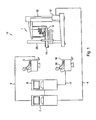
- Figure 1 is a view of a rig control and monitoring system
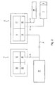
- Figure 2 is a view of a communication structure with corresponding communication links used according to Figure 1 .
- FIG 1 is a view of one embodiment of a rig control and monitoring system 11 according to the invention.
- the rig control and monitoring system 11 includes a piece of well bore equipment 1, which in turn includes a rig control system 15, which may include a Power Frame TM available from Weatherford International of Houston, Texas, or a Torq Winder TM , also available from Weatherford International.
- a rig control system 15 is typically used for operating a tong 14 which holds a tube or casing 28.
- One sensor module 6 is assigned to this system 15.
- the sensor module 6 may be, for example, a JAM (joint analyzed makeup) monitoring means, also available from Weatherford International.
- JAM joint analyzed makeup
- Such a JAM monitoring means is used to monitor torque, turns and rotations per minute of the tong to ensure that all tubing and casing connections confirm to a manufacturer's specification.
- the corresponding parameters monitored by the sensor module are typically torque and turns.
- the data corresponding to the measured parameter is submitted by the sensor module to an individual control means 10 assigned to the corresponding well bore equipment 1.
- the communication link 4 may be a wire transmission link or a field bus link.
- Examples for such a field bus are Profibus, Interbus, CANBus, LightBus or even other communication links as RS232 or RS485 or others.
- One universal data acquisition and control system 2 suitable for use in this invention is a HiPerTM control system available from Weatherford, which is an operating platform suitable for all mechanized rig systems in which the corresponding components can be operated remotely by utilizing this system.
- the collected data is transmitted by communication link 8 to personnel or an operator working at a distance from sensor module 6.
- the operator may be located onshore when the well site is offshore.
- the communication link 8 is realized by a bus transmission such as Ethernet.
- the connection over Ethernet is in general a TCP/IP connection.
- the operator uses a remote control/monitoring unit 3 which may be, for example, a laptop computer.
- This laptop serves as a display unit and may also serve as an evaluation unit for the data received from the universal data acquisition and control system 2.
- wireless transmissions for example, radio transmission via satellite, or a fiber optic transmission.
- the communication links 4, 8 are fully duplex, and it is also possible to retransmit control data from the remote control/monitoring unit 3 to the universal data acquisition and control system 2. These control data may then be used by the universal data acquisition and control system 2 to modify or adjust well bore equipment 1 such that the parameter measured by sensor module 6 is within predefined limits or such control data may be used to stop the operation of the corresponding well bore equipment 1.
- Another universal data acquisition and control system 9 may be connected to system 2 through a communication link 17, and may also be used to remotely control the well bore equipment 1 from another computer or laptop 16 wherein the corresponding operator is arranged offshore, i.e. on rig site. This operator directly controls the well bore equipment 1 and may also receive the control data from the remote control/monitoring unit 3 for adjusting his operation in response to the received control data.
- a load cell for torque measuring and a turn counter may transmit data to the universal data acquisition and control system as a generalized measuring device.
- the corresponding control data received by the universal data acquisition and control system 2 may be transmitted to a corresponding valve control block assigned to the corresponding well bore equipment 1 is operated via system 2 for control of tong speed and torque.
- sensor modules measure other parameters as for example temperature, pressure, flow etc.
- the sensor module may also detect a leak or the like.
- FIG 2 is a more detailed view of the communication structure used by the rig control and monitoring system 11 according to Figure 1 .
- the universal data acquisition and control system 2 comprises for example a memory storage means 5 which may be used for immediate storage of data collected from one or more sensor modules 6.
- this memory storage means 5 may also be used for storing other data of the well bore equipment 1 or for storing control data received from the remote control/monitoring unit 3.
- the universal data acquisition and control system 2 further comprises a programmable logic control device 21 and interfaces 24 and 25 for the corresponding communication links to the remote control/monitoring unit 3 and the sensor module 6 or well bore equipment 1 and further remote control means 16, see the operator 29 in figure 1 with laptop 16.
- the communication link between laptop 16 of operator 29 or sensor module 6/well bore equipment 1 and universal data acquisition and control system 2 is realized by a field bus 17 which may be a Profibus, Interbus, RS232, RS485 or others.
- the other interface 24 is used for realizing the communication link to the remote control/monitoring unit 3 by Ethernet 8.
- this communication is a radio transmission via satellite, a fiber optic transmission, etc.
- the remote control/monitoring unit 3 also comprises another interface 20 and further a display means 12 and a storage means 13.
- the display means 12 is used for visualizing the evaluated data received from the universal data acquisition and control system 2 as a graph, a table, etc.
- a corresponding evaluation module 22 is stored in the remote control/monitoring unit, wherein, the evaluation module 22 may be provided on any kind of at least readable storage means.
- the corresponding or general communication link 8, such as Ethernet, between remote control/monitoring unit 3 and universal data acquisition and control system is also used for forwarding an interpretation of the data to the corresponding rig control system 15 or well bore equipment 1 such that it can be immediately decided if the parameters are in predefined limits.
- the applied torque and rotation in making up a shouldered tubular connection are measured at regular intervals throughout a pipe connection makeup.
- the rate of change of torque with rotation (derivative) is calculated for each set of measurements.
- These three values are then compared either continuously or at selected rotational positions, with minimum and maximum acceptable predetermined values, and a decision made whether to continue rotation or abort the makeup.
- the derivative (rate of change of torque) is compared with predetermined threshold values to determine seal and shoulder contact points. The change in torque and rotation between these two detected contact points is checked to ensure that the change is within a predetermined acceptable range.
- a predetermined torque value and/or rotation value is added to the measured torque and/or rotation values, respectively, at shoulder contact and rotation continued until this calculated value(s) is reached.
- the application of torque is terminated and the reverse rotation of a tubing length is monitored as the connection relaxes. If the relaxation is within an acceptable predetermined range and the above conditions are met then the makeup is considered acceptable.
- the invention it is in particular possible to remove personnel from the well bore or well center area on the rig without interruption of the operation of the well bore equipment due to safety reasons as there may be an intermediate response back from the remote control/monitoring unit 3 to the universal data acquisition and control system 2 and further to the corresponding well bore equipment 1 or rig control system 15. Consequently, there is not only real time data acquisition and evaluation according to the method of the invention but also real time operation of the corresponding well bore equipment or rig control system to react on the evaluation of the collected data.
- information can be displayed in other useful ways, especially information related to operating variables of automated equipment on a rig floor.
- information can be displayed in other useful ways, especially information related to operating variables of automated equipment on a rig floor.
- utilizing the hardware and software described herein it is possible to display items in a three dimensional format whereby variables like torque, turns, and time are independently illustrated along with their relationship to each other.
- this three dimensional format it is also possible to dissect the image to give a snap shot of any one or two of the variables at any particular time. In this manner, the make up of a joint, for instance can be analysed at any time.
- the universal data acquisition and control system Because of the plurality of sensor modules, the universal data acquisition and control system, additional control system, control/monitoring units, it is of advantage when all these devices are synchronized.
- it may comprise a programmable logic control means.
Landscapes
- Engineering & Computer Science (AREA)
- Geology (AREA)
- Life Sciences & Earth Sciences (AREA)
- Mining & Mineral Resources (AREA)
- Physics & Mathematics (AREA)
- Environmental & Geological Engineering (AREA)
- Fluid Mechanics (AREA)
- General Life Sciences & Earth Sciences (AREA)
- Geochemistry & Mineralogy (AREA)
- Geophysics (AREA)
- Mechanical Engineering (AREA)
- Arrangements For Transmission Of Measured Signals (AREA)
- Selective Calling Equipment (AREA)
Claims (11)
- Verfahren zum Fernsteuern und/oder Überwachen des Zusammensetzens einer Röhrenverbindung, umfassend:Drehen einer ersten Gewinderöhre relativ zu einer zweiten Gewinderöhre, worin jede der Gewinderöhren einen Absatz umfasst; undwährend der Drehung der ersten Gewinderöhre:Messen des Drehmoments;Messen der Drehung;Messen der Zeit;Übertragen des Drehmomentmesswerts zu einer Fernsteuerungs-/Überwachungseinheit (3) über eine drahtlose Kommunikationsverbindung (8);Berechnen einer Änderungsgeschwindigkeit des Drehmoments in Bezug auf die Drehung;Ermitteln einer Absatzberührung durch Überwachen der Änderungsgeschwindigkeit des Drehmoments in Bezug auf die Drehung; und gekennzeichnet durch:Anhalten der Drehung der ersten Röhre, wenn ein vordefinierter Drehungswert von der Absatzberührung erreicht wird.
- Verfahren nach Anspruch 1, ferner umfassend: Bestimmen der Annahmetauglichkeit der Schraubverbindung.
- Verfahren nach Anspruch 1 oder 2, worin die Fernsteuerungs-/Überwachungseinheit (3) die Änderungsgeschwindigkeit des Drehmoments in Bezug auf die Drehung berechnet und die Absatzberührung ermittelt.
- Verfahren nach Anspruch 1, 2 oder 3, worin die Röhren auf See sind und die Fernsteuerungs-/Überwachungseinheit (3) an Land ist.
- Verfahren nach einem der vorhergehenden Ansprüche, worin der Drehungsmesswert ebenfalls über die drahtlose Kommunikationsverbindung (8) zur Fernsteuerungs-/Überwachungseinheit (3) übertragen wird.
- Verfahren nach einem der vorhergehenden Ansprüche, ferner umfassend: grafisches Anzeigen der Drehmoment-, Drehungs- und Zeitmesswerte in einem dreidimensionalen Format.
- Bohranlagensteuerungs- und -überwachungssystem (11), umfassend:mindestens ein Exemplar von mechanisierter Ölfeld-Röhrenhandhabungsausrüstung (1), umfassend ein Drehmomentsensormodul (6) und ein Umdrehungszählersensormodul, worin die Ausrüstung betriebsfähig ist zum:Drehen einer ersten Gewinderöhre relativ zu einer zweiten Gewinderöhre, worin jede der Gewinderöhren einen Absatz umfasst; undwährend der Drehung der ersten Gewinderöhre:Messen des Drehmoments,Messen der Drehung,Messen der Zeit, undÜbertragen des Drehmomentmesswerts zu einer Fernsteuerungs-/Überwachungseinheit über eine drahtlose Kommunikationsverbindung; unddie Fernsteuerungs-/Überwachungseinheit betriebsfähig ist zum:Berechnen einer Änderungsgeschwindigkeit des Drehmoments in Bezug auf die Drehung;Ermitteln einer Absatzberührung durch Überwachen der Änderungsgeschwindigkeit des Drehmoments in Bezug auf die Drehung; und gekennzeichnet ist durch:Anhalten der Drehung der ersten Röhre, wenn ein vordefinierter Drehungswert von der Absatzberührung erreicht wird.
- System nach Anspruch 7, worin die Fernsteuerungs-/Überwachungseinheit ferner betriebsfähig ist, die Annahmetauglichkeit der Schraubverbindung zu bestimmen.
- System nach Anspruch 7 oder 8, worin die Ausrüstung (1) auf See ist und die Fernsteuerungs-/Überwachungseinheit (3) an Land ist.
- System nach Anspruch 7, 8 oder 9, worin die Ausrüstung (1) ferner betriebsfähig ist, den Drehungsmesswert über die drahtlose Kommunikationsverbindung (8) zur Fernsteuerungs-/Überwachungseinheit zu übertragen.
- System nach einem der Ansprüche 7 bis 10, worin die Fernsteuerungs-/Überwachungseinheit (3) ferner betriebsfähig ist, die Drehmoment-, Drehungs- und Zeitmesswerte in einem dreidimensionalen Format grafisch anzuzeigen.
Applications Claiming Priority (2)
| Application Number | Priority Date | Filing Date | Title |
|---|---|---|---|
| US10/360,547 US6896055B2 (en) | 2003-02-06 | 2003-02-06 | Method and apparatus for controlling wellbore equipment |
| EP04250651A EP1445419B1 (de) | 2003-02-06 | 2004-02-06 | Verfahren und Vorrichtung zur Steuerung einer Bohrlocheinrichtung |
Related Parent Applications (1)
| Application Number | Title | Priority Date | Filing Date |
|---|---|---|---|
| EP04250651A Division EP1445419B1 (de) | 2003-02-06 | 2004-02-06 | Verfahren und Vorrichtung zur Steuerung einer Bohrlocheinrichtung |
Publications (3)
| Publication Number | Publication Date |
|---|---|
| EP1978206A2 EP1978206A2 (de) | 2008-10-08 |
| EP1978206A3 EP1978206A3 (de) | 2008-10-15 |
| EP1978206B1 true EP1978206B1 (de) | 2012-10-17 |
Family
ID=32655656
Family Applications (2)
| Application Number | Title | Priority Date | Filing Date |
|---|---|---|---|
| EP04250651A Expired - Lifetime EP1445419B1 (de) | 2003-02-06 | 2004-02-06 | Verfahren und Vorrichtung zur Steuerung einer Bohrlocheinrichtung |
| EP08009538A Expired - Lifetime EP1978206B1 (de) | 2003-02-06 | 2004-02-06 | Verfahren und Vorrichtung zur Steuerung von Bohrlochgeräten |
Family Applications Before (1)
| Application Number | Title | Priority Date | Filing Date |
|---|---|---|---|
| EP04250651A Expired - Lifetime EP1445419B1 (de) | 2003-02-06 | 2004-02-06 | Verfahren und Vorrichtung zur Steuerung einer Bohrlocheinrichtung |
Country Status (5)
| Country | Link |
|---|---|
| US (1) | US6896055B2 (de) |
| EP (2) | EP1445419B1 (de) |
| AU (1) | AU2004200433B2 (de) |
| CA (1) | CA2457078C (de) |
| NO (1) | NO342133B1 (de) |
Families Citing this family (78)
| Publication number | Priority date | Publication date | Assignee | Title |
|---|---|---|---|---|
| US6536520B1 (en) | 2000-04-17 | 2003-03-25 | Weatherford/Lamb, Inc. | Top drive casing system |
| US7264050B2 (en) * | 2000-09-22 | 2007-09-04 | Weatherford/Lamb, Inc. | Method and apparatus for controlling wellbore equipment |
| US7278540B2 (en) * | 2004-04-29 | 2007-10-09 | Varco I/P, Inc. | Adjustable basket vibratory separator |
| US20050242003A1 (en) * | 2004-04-29 | 2005-11-03 | Eric Scott | Automatic vibratory separator |
| US7331469B2 (en) * | 2004-04-29 | 2008-02-19 | Varco I/P, Inc. | Vibratory separator with automatically adjustable beach |
| US8312995B2 (en) * | 2002-11-06 | 2012-11-20 | National Oilwell Varco, L.P. | Magnetic vibratory screen clamping |
| US7571817B2 (en) * | 2002-11-06 | 2009-08-11 | Varco I/P, Inc. | Automatic separator or shaker with electromagnetic vibrator apparatus |
| US20060113220A1 (en) * | 2002-11-06 | 2006-06-01 | Eric Scott | Upflow or downflow separator or shaker with piezoelectric or electromagnetic vibrator |
| SE528911C2 (sv) * | 2005-01-19 | 2007-03-13 | Atlas Copco Rock Drills Ab | Förfarande och system för övervakning och dokumentering av installation av bergförstärkningsbult |
| US7539548B2 (en) * | 2005-02-24 | 2009-05-26 | Sara Services & Engineers (Pvt) Ltd. | Smart-control PLC based touch screen driven remote control panel for BOP control unit |
| US7604072B2 (en) * | 2005-06-07 | 2009-10-20 | Baker Hughes Incorporated | Method and apparatus for collecting drill bit performance data |
| US8100196B2 (en) * | 2005-06-07 | 2012-01-24 | Baker Hughes Incorporated | Method and apparatus for collecting drill bit performance data |
| US8376065B2 (en) * | 2005-06-07 | 2013-02-19 | Baker Hughes Incorporated | Monitoring drilling performance in a sub-based unit |
| US7849934B2 (en) * | 2005-06-07 | 2010-12-14 | Baker Hughes Incorporated | Method and apparatus for collecting drill bit performance data |
| US20070044959A1 (en) * | 2005-09-01 | 2007-03-01 | Baker Hughes Incorporated | Apparatus and method for evaluating a formation |
| CA2586317C (en) | 2006-04-27 | 2012-04-03 | Weatherford/Lamb, Inc. | Torque sub for use with top drive |
| WO2008022425A1 (en) * | 2006-08-24 | 2008-02-28 | Canrig Drilling Technology Ltd. | Oilfield tubular torque wrench |
| WO2008022424A1 (en) * | 2006-08-24 | 2008-02-28 | Canrig Drilling Technology Ltd. | Oilfield tubular torque wrench |
| CA2661405C (en) * | 2006-08-25 | 2013-01-08 | Canrig Drilling Technology Ltd. | Methods and apparatus for automated oilfield torque wrench set-up to make-up and break-out tubular strings |
| US8074537B2 (en) | 2006-09-08 | 2011-12-13 | Canrig Drilling Technology Ltd. | Oilfield tubular spin-in and spin-out detection for making-up and breaking-out tubular strings |
| US20080083566A1 (en) | 2006-10-04 | 2008-04-10 | George Alexander Burnett | Reclamation of components of wellbore cuttings material |
| US20080154510A1 (en) * | 2006-12-21 | 2008-06-26 | Chevron U.S.A. Inc. | Method and system for automated choke control on a hydrocarbon producing well |
| US20080190604A1 (en) * | 2007-02-09 | 2008-08-14 | International Business Machines Corporation | System and Method for Coordinated Monitoring and Control of Multiple Oil Well Pump Systems |
| US7519503B2 (en) * | 2007-02-15 | 2009-04-14 | Epsis As | Data handling system |
| US8622220B2 (en) | 2007-08-31 | 2014-01-07 | Varco I/P | Vibratory separators and screens |
| US20090210813A1 (en) * | 2008-02-15 | 2009-08-20 | Sawczak Stephen D | Systems and methods for computer equipment management |
| US8155942B2 (en) * | 2008-02-21 | 2012-04-10 | Chevron U.S.A. Inc. | System and method for efficient well placement optimization |
| US7819183B2 (en) | 2008-06-16 | 2010-10-26 | Halliburton Energy Services, Inc. | Work string controller |
| US9073104B2 (en) | 2008-08-14 | 2015-07-07 | National Oilwell Varco, L.P. | Drill cuttings treatment systems |
| US8556083B2 (en) | 2008-10-10 | 2013-10-15 | National Oilwell Varco L.P. | Shale shakers with selective series/parallel flow path conversion |
| US9079222B2 (en) | 2008-10-10 | 2015-07-14 | National Oilwell Varco, L.P. | Shale shaker |
| US9527140B2 (en) * | 2009-02-05 | 2016-12-27 | Minnich Manufacturing Company, Inc. | Drilling apparatus |
| US20100252325A1 (en) * | 2009-04-02 | 2010-10-07 | National Oilwell Varco | Methods for determining mechanical specific energy for wellbore operations |
| US9567843B2 (en) * | 2009-07-30 | 2017-02-14 | Halliburton Energy Services, Inc. | Well drilling methods with event detection |
| US9528334B2 (en) | 2009-07-30 | 2016-12-27 | Halliburton Energy Services, Inc. | Well drilling methods with automated response to event detection |
| US8381838B2 (en) | 2009-12-31 | 2013-02-26 | Pason Systems Corp. | System and apparatus for directing the drilling of a well |
| GB2478915B (en) * | 2010-03-22 | 2012-11-07 | Stingray Geophysical Ltd | Sensor array |
| US20130008718A1 (en) * | 2010-03-26 | 2013-01-10 | Vermeer Manufacturing Company | Control system and interface for a tunneling apparatus |
| CA2799402C (en) | 2010-05-14 | 2020-10-06 | Harnischfeger Technologies, Inc. | Cycle decomposition analysis for remote machine monitoring |
| US8689866B2 (en) * | 2011-04-28 | 2014-04-08 | Canrig Drilling Technology Ltd. | Automated systems and methods for make-up and break-out of tubulars |
| CN102322253B (zh) * | 2011-05-06 | 2015-08-12 | 三一重工股份有限公司 | 一种工程机械及其工况控制方法、装置 |
| US8949416B1 (en) * | 2012-01-17 | 2015-02-03 | Canyon Oak Energy LLC | Master control system with remote monitoring for handling tubulars |
| US20140095658A1 (en) * | 2012-10-02 | 2014-04-03 | Transocean Sedco Forex Ventures Limited | Information Aggregation on a Mobile Offshore Drilling Unit |
| AU2013337757B2 (en) * | 2012-10-31 | 2016-10-20 | Weatherford Technology Holdings, Llc | Graphical evaluator for tubular makeup |
| US9643111B2 (en) | 2013-03-08 | 2017-05-09 | National Oilwell Varco, L.P. | Vector maximizing screen |
| MX366941B (es) | 2013-03-15 | 2019-07-31 | Wellaware Holdings Inc | Sistemas y métodos para proporcionar seguimiento y/o control, de principio a fin, de activos remotos de producción de petróleo y gas. |
| US20170122092A1 (en) | 2015-11-04 | 2017-05-04 | Schlumberger Technology Corporation | Characterizing responses in a drilling system |
| WO2017132297A2 (en) | 2016-01-26 | 2017-08-03 | Schlumberger Technology Corporation | Tubular measurement |
| CN109328256A (zh) | 2016-05-25 | 2019-02-12 | 斯伦贝谢技术有限公司 | 基于图像的钻井作业系统 |
| US11021944B2 (en) | 2017-06-13 | 2021-06-01 | Schlumberger Technology Corporation | Well construction communication and control |
| US11143010B2 (en) | 2017-06-13 | 2021-10-12 | Schlumberger Technology Corporation | Well construction communication and control |
| US11422999B2 (en) | 2017-07-17 | 2022-08-23 | Schlumberger Technology Corporation | System and method for using data with operation context |
| CN107780919A (zh) * | 2017-09-22 | 2018-03-09 | 中国石油集团西部钻探工程有限公司 | 远程气井控制柜及其远程控制方法 |
| US10808474B2 (en) * | 2017-10-24 | 2020-10-20 | Weatherford Technology Holdings, Llc | Method and system for evaluating tubular makeup |
| DE112019001243T5 (de) | 2018-03-09 | 2020-11-26 | Schlumberger Technology B.V. | Integrierte Bohrlochkonstruktionssystem-Betriebsvorgänge |
| US11035219B2 (en) | 2018-05-10 | 2021-06-15 | Schlumberger Technology Corporation | System and method for drilling weight-on-bit based on distributed inputs |
| US10876834B2 (en) | 2018-05-11 | 2020-12-29 | Schlumberger Technology Corporation | Guidance system for land rig assembly |
| US20190368286A1 (en) * | 2018-05-31 | 2019-12-05 | Schlumberger Technology Corporation | Torque turn logger |
| US12366152B2 (en) | 2018-06-04 | 2025-07-22 | Schlumberger Technology Corporation | Well construction workstation and control |
| US11613009B2 (en) | 2018-08-07 | 2023-03-28 | Frank's International, Llc | Connection analyzed make-up systems and methods |
| US10890060B2 (en) | 2018-12-07 | 2021-01-12 | Schlumberger Technology Corporation | Zone management system and equipment interlocks |
| US10907466B2 (en) | 2018-12-07 | 2021-02-02 | Schlumberger Technology Corporation | Zone management system and equipment interlocks |
| US10844675B2 (en) | 2018-12-21 | 2020-11-24 | Weatherford Technology Holdings, Llc | Autonomous connection makeup and evaluation |
| US12000269B2 (en) | 2019-04-05 | 2024-06-04 | Mccoy Global Inc. | Method and system for monitoring, communicating and controlling completion related operations |
| US11643891B2 (en) | 2019-06-06 | 2023-05-09 | Weatherford Technology Holdings, Llc | Drilling system and method using calibrated pressure losses |
| CA3145945C (en) * | 2019-08-13 | 2022-06-21 | Spencer P. Taubner | Systems and methods for detecting steps in tubular connection processes |
| US11047224B2 (en) | 2019-08-28 | 2021-06-29 | Weatherford Technology Holdings, Llc | Automatic compensation for surge and swab during pipe movement in managed pressure drilling operation |
| US11514383B2 (en) | 2019-09-13 | 2022-11-29 | Schlumberger Technology Corporation | Method and system for integrated well construction |
| US20210080938A1 (en) * | 2019-09-17 | 2021-03-18 | Schlumberger Technology Corporation | Smart historian for rig equipment |
| US11391142B2 (en) | 2019-10-11 | 2022-07-19 | Schlumberger Technology Corporation | Supervisory control system for a well construction rig |
| US12055027B2 (en) | 2020-03-06 | 2024-08-06 | Schlumberger Technology Corporation | Automating well construction operations based on detected abnormal events |
| CN111443678A (zh) * | 2020-04-16 | 2020-07-24 | 河南省百世联智能科技有限公司 | 一种移动式监控数据监测终端及使用方法 |
| US20220010669A1 (en) * | 2020-07-10 | 2022-01-13 | Reign RMC, LLC | Marginal well monitoring and control systems and methods |
| NO20230584A1 (en) | 2020-11-19 | 2023-05-19 | Schlumberger Technology Bv | Interactive monitoring and control system for a mineral extraction system |
| US11824682B1 (en) | 2023-01-27 | 2023-11-21 | Schlumberger Technology Corporation | Can-open master redundancy in PLC-based control system |
| CN115865683B (zh) * | 2023-03-02 | 2023-05-23 | 山东创安交通预警工程有限公司 | 智慧社区设备管理系统 |
| US12134942B2 (en) | 2023-03-10 | 2024-11-05 | Baker Hughes Oilfield Operations Llc | Control of tubular connections based on estimation of turns remaining |
| CN117166970B (zh) * | 2023-09-15 | 2024-04-02 | 大庆石油管理局有限公司 | 一种塔架式抽油机远程监测系统及方法 |
Family Cites Families (20)
| Publication number | Priority date | Publication date | Assignee | Title |
|---|---|---|---|---|
| US4738145A (en) * | 1982-06-01 | 1988-04-19 | Tubular Make-Up Specialists, Inc. | Monitoring torque in tubular goods |
| USRE34063E (en) | 1982-06-01 | 1992-09-15 | Monitoring torque in tubular goods | |
| GB8326736D0 (en) * | 1983-10-06 | 1983-11-09 | Salvesen Drilling Services | Analysis of torque applied to joint |
| GB8901918D0 (en) * | 1989-01-28 | 1989-03-15 | Franks Casing Crews Uk Limited | Control system |
| GB2247904A (en) | 1990-09-13 | 1992-03-18 | Axl Systems Ltd | Identifying metal articles |
| US5233742A (en) * | 1992-06-29 | 1993-08-10 | Gray N Monroe | Method and apparatus for controlling tubular connection make-up |
| US5402688A (en) * | 1993-03-17 | 1995-04-04 | Sumitomo Metal Industries, Ltd. | Method and apparatus for determining the tightened condition of a pipe joint |
| GB2334282B (en) * | 1995-02-09 | 1999-09-29 | Baker Hughes Inc | A remotely controlled valve and variable choke assembly |
| US5706896A (en) | 1995-02-09 | 1998-01-13 | Baker Hughes Incorporated | Method and apparatus for the remote control and monitoring of production wells |
| JP3959552B2 (ja) * | 1996-06-03 | 2007-08-15 | 忠弘 大見 | 配管施工の締付の管理方法 |
| US5955666A (en) * | 1997-03-12 | 1999-09-21 | Mullins; Augustus Albert | Satellite or other remote site system for well control and operation |
| US6281489B1 (en) * | 1997-05-02 | 2001-08-28 | Baker Hughes Incorporated | Monitoring of downhole parameters and tools utilizing fiber optics |
| US6787758B2 (en) * | 2001-02-06 | 2004-09-07 | Baker Hughes Incorporated | Wellbores utilizing fiber optic-based sensors and operating devices |
| US6766854B2 (en) * | 1997-06-02 | 2004-07-27 | Schlumberger Technology Corporation | Well-bore sensor apparatus and method |
| AU8164898A (en) * | 1997-06-27 | 1999-01-19 | Baker Hughes Incorporated | Drilling system with sensors for determining properties of drilling fluid downhole |
| US6385837B1 (en) | 1999-04-05 | 2002-05-14 | Central Motor Wheel Co., Ltd. | Method and apparatus for fixedly connecting threaded tubes, and recording medium storing control program for practicing or controlling those method and apparatus |
| WO2002057805A2 (en) * | 2000-06-29 | 2002-07-25 | Tubel Paulo S | Method and system for monitoring smart structures utilizing distributed optical sensors |
| US6405135B1 (en) * | 2000-07-18 | 2002-06-11 | John J. Adriany | System for remote detection and notification of subterranean pollutants |
| AU2001287866A1 (en) | 2000-09-22 | 2002-04-02 | David Michael Haugen | Methods and apparatus for interactive communications |
| US6491828B1 (en) * | 2000-11-07 | 2002-12-10 | General Electric Company | Method and system to remotely monitor groundwater treatment |
-
2003
- 2003-02-06 US US10/360,547 patent/US6896055B2/en not_active Expired - Lifetime
-
2004
- 2004-02-05 NO NO20040522A patent/NO342133B1/no not_active IP Right Cessation
- 2004-02-05 CA CA2457078A patent/CA2457078C/en not_active Expired - Fee Related
- 2004-02-06 EP EP04250651A patent/EP1445419B1/de not_active Expired - Lifetime
- 2004-02-06 EP EP08009538A patent/EP1978206B1/de not_active Expired - Lifetime
- 2004-02-06 AU AU2004200433A patent/AU2004200433B2/en not_active Ceased
Also Published As
| Publication number | Publication date |
|---|---|
| AU2004200433B2 (en) | 2009-01-08 |
| CA2457078C (en) | 2011-10-18 |
| US20040154832A1 (en) | 2004-08-12 |
| NO20040522L (no) | 2004-08-09 |
| NO342133B1 (no) | 2018-03-26 |
| AU2004200433A1 (en) | 2004-08-26 |
| EP1978206A2 (de) | 2008-10-08 |
| EP1445419B1 (de) | 2009-01-14 |
| CA2457078A1 (en) | 2004-08-06 |
| US6896055B2 (en) | 2005-05-24 |
| EP1978206A3 (de) | 2008-10-15 |
| EP1445419A1 (de) | 2004-08-11 |
Similar Documents
| Publication | Publication Date | Title |
|---|---|---|
| CA2457078C (en) | Method and apparatus for controlling wellbore equipment | |
| US7264050B2 (en) | Method and apparatus for controlling wellbore equipment | |
| CA2448419C (en) | Instrumentation for a downhole deployment valve | |
| US20200224524A1 (en) | Utilizing Vision Systems at a Wellsite | |
| EP3947896B1 (de) | Automatisiertes system und verfahren zur verwendung in der bohrlochsteuerung | |
| US12366130B2 (en) | Communicating with blowout preventer control system | |
| US20200224526A1 (en) | Utilizing Vision Systems at a Wellsite | |
| US20200224523A1 (en) | Utilizing Vision Systems at a Wellsite | |
| US20200224525A1 (en) | Utilizing Vision Systems at a Wellsite | |
| JP2016533549A (ja) | 非侵入型センサシステム | |
| US20180171760A1 (en) | Relationship Tagging of Data in Well Construction | |
| CN111226022A (zh) | 无线紧急停止 | |
| KR102331841B1 (ko) | 조인트 인식 시스템 | |
| US20070278009A1 (en) | Method and Apparatus for Sensing Downhole Characteristics | |
| US20210177341A1 (en) | Utilizing wearable electronic devices at a worksite | |
| US11187714B2 (en) | Processing downhole rotational data | |
| US11761273B2 (en) | Determining stickup height based on pipe tally, block position, and digital images | |
| CN116437247A (zh) | 一种井下异常信息上传方法和上传系统 | |
| WO2018101968A1 (en) | Anomaly detection systems and methods employing a downhole tool with axially-spaced sensor packages | |
| US12352158B2 (en) | Downhole fault detection in well system using spread spectrum time domain reflectometry (SSTDR) | |
| US12158046B2 (en) | Maintaining torque wrenches using a predictive model | |
| CN120889564A (zh) | 一种基于dc指数的地层压力监测系统 | |
| WO2001092686A1 (en) | Webserver-based well instrumentation, logging, monitoring and control |
Legal Events
| Date | Code | Title | Description |
|---|---|---|---|
| PUAI | Public reference made under article 153(3) epc to a published international application that has entered the european phase |
Free format text: ORIGINAL CODE: 0009012 |
|
| PUAL | Search report despatched |
Free format text: ORIGINAL CODE: 0009013 |
|
| 17P | Request for examination filed |
Effective date: 20080526 |
|
| AC | Divisional application: reference to earlier application |
Ref document number: 1445419 Country of ref document: EP Kind code of ref document: P |
|
| AK | Designated contracting states |
Kind code of ref document: A2 Designated state(s): GB IT NL |
|
| AK | Designated contracting states |
Kind code of ref document: A3 Designated state(s): GB IT NL |
|
| AKX | Designation fees paid |
Designated state(s): GB IT NL |
|
| 17Q | First examination report despatched |
Effective date: 20110928 |
|
| GRAP | Despatch of communication of intention to grant a patent |
Free format text: ORIGINAL CODE: EPIDOSNIGR1 |
|
| GRAS | Grant fee paid |
Free format text: ORIGINAL CODE: EPIDOSNIGR3 |
|
| GRAA | (expected) grant |
Free format text: ORIGINAL CODE: 0009210 |
|
| AC | Divisional application: reference to earlier application |
Ref document number: 1445419 Country of ref document: EP Kind code of ref document: P |
|
| AK | Designated contracting states |
Kind code of ref document: B1 Designated state(s): GB IT NL |
|
| REG | Reference to a national code |
Ref country code: GB Ref legal event code: FG4D |
|
| REG | Reference to a national code |
Ref country code: NL Ref legal event code: T3 |
|
| PLBE | No opposition filed within time limit |
Free format text: ORIGINAL CODE: 0009261 |
|
| STAA | Information on the status of an ep patent application or granted ep patent |
Free format text: STATUS: NO OPPOSITION FILED WITHIN TIME LIMIT |
|
| 26N | No opposition filed |
Effective date: 20130718 |
|
| REG | Reference to a national code |
Ref country code: NL Ref legal event code: SD Effective date: 20150318 |
|
| REG | Reference to a national code |
Ref country code: GB Ref legal event code: 732E Free format text: REGISTERED BETWEEN 20151029 AND 20151104 |
|
| PGFP | Annual fee paid to national office [announced via postgrant information from national office to epo] |
Ref country code: IT Payment date: 20180221 Year of fee payment: 15 |
|
| PG25 | Lapsed in a contracting state [announced via postgrant information from national office to epo] |
Ref country code: IT Free format text: LAPSE BECAUSE OF NON-PAYMENT OF DUE FEES Effective date: 20190206 |
|
| REG | Reference to a national code |
Ref country code: NL Ref legal event code: RC Free format text: DETAILS LICENCE OR PLEDGE: RIGHT OF PLEDGE, ESTABLISHED Name of requester: DEUTSCHE BANK TRUST COMPANY AMERICAS Effective date: 20200723 |
|
| REG | Reference to a national code |
Ref country code: GB Ref legal event code: 732E Free format text: REGISTERED BETWEEN 20200813 AND 20200819 |
|
| REG | Reference to a national code |
Ref country code: GB Ref legal event code: 732E Free format text: REGISTERED BETWEEN 20201126 AND 20201202 |
|
| REG | Reference to a national code |
Ref country code: GB Ref legal event code: 732E Free format text: REGISTERED BETWEEN 20210225 AND 20210303 |
|
| PGFP | Annual fee paid to national office [announced via postgrant information from national office to epo] |
Ref country code: NL Payment date: 20210212 Year of fee payment: 18 |
|
| PGFP | Annual fee paid to national office [announced via postgrant information from national office to epo] |
Ref country code: GB Payment date: 20211216 Year of fee payment: 19 |
|
| REG | Reference to a national code |
Ref country code: NL Ref legal event code: MM Effective date: 20220301 |
|
| PG25 | Lapsed in a contracting state [announced via postgrant information from national office to epo] |
Ref country code: NL Free format text: LAPSE BECAUSE OF NON-PAYMENT OF DUE FEES Effective date: 20220301 |
|
| GBPC | Gb: european patent ceased through non-payment of renewal fee |
Effective date: 20230206 |
|
| PG25 | Lapsed in a contracting state [announced via postgrant information from national office to epo] |
Ref country code: GB Free format text: LAPSE BECAUSE OF NON-PAYMENT OF DUE FEES Effective date: 20230206 |
|
| PG25 | Lapsed in a contracting state [announced via postgrant information from national office to epo] |
Ref country code: GB Free format text: LAPSE BECAUSE OF NON-PAYMENT OF DUE FEES Effective date: 20230206 |