EP1978368B1 - Vorrichtung zur automatischen sukzessiven Online-Entnahme einer Serie von Proben aus einer zu analysierenden Flüssigkeit sowie Umsetzungsverfahren nach dem Einsatz einer solchen Vorrichtung - Google Patents
Vorrichtung zur automatischen sukzessiven Online-Entnahme einer Serie von Proben aus einer zu analysierenden Flüssigkeit sowie Umsetzungsverfahren nach dem Einsatz einer solchen Vorrichtung Download PDFInfo
- Publication number
- EP1978368B1 EP1978368B1 EP08300117A EP08300117A EP1978368B1 EP 1978368 B1 EP1978368 B1 EP 1978368B1 EP 08300117 A EP08300117 A EP 08300117A EP 08300117 A EP08300117 A EP 08300117A EP 1978368 B1 EP1978368 B1 EP 1978368B1
- Authority
- EP
- European Patent Office
- Prior art keywords
- sample
- liquid
- valve
- sample reservoir
- analysis cell
- Prior art date
- Legal status (The legal status is an assumption and is not a legal conclusion. Google has not performed a legal analysis and makes no representation as to the accuracy of the status listed.)
- Active
Links
Images


Classifications
-
- G—PHYSICS
- G01—MEASURING; TESTING
- G01N—INVESTIGATING OR ANALYSING MATERIALS BY DETERMINING THEIR CHEMICAL OR PHYSICAL PROPERTIES
- G01N35/00—Automatic analysis not limited to methods or materials provided for in any single one of groups G01N1/00 - G01N33/00; Handling materials therefor
- G01N35/10—Devices for transferring samples or any liquids to, in, or from, the analysis apparatus, e.g. suction devices, injection devices
- G01N35/1095—Devices for transferring samples or any liquids to, in, or from, the analysis apparatus, e.g. suction devices, injection devices for supplying the samples to flow-through analysers
- G01N35/1097—Devices for transferring samples or any liquids to, in, or from, the analysis apparatus, e.g. suction devices, injection devices for supplying the samples to flow-through analysers characterised by the valves
Definitions
- the subject of the present invention is a device for successive automatic sampling in line, on a main pipeline, in particular on a pipeline of an installation for the industrial production of petroleum products, of a series of samples of a liquid to be analyzed in an analysis cell.
- such an analysis cell may advantageously be constituted by an automatic distillation apparatus suitable for measuring the distillation parameters of samples of petroleum products. respecting a predefined test standard.
- distillation parameters of petroleum products are representative of the performance of these products as well as the risks that they may incur to their users.
- mini-distillation apparatuses are further distinguished by the fact that the characteristics of the samples analyzed are directly determined from temperature and pressure measurements, without the need to measure the volume of condensate collected in the measuring cylinder.
- Such laboratory apparatus which is for example described in the document FR 2 815 413 , are equipped with analysis flasks whose spherical portion cooperates with a heating element such as a heating resistor and whose neck has a lateral capillary connected to a condenser tube and is closed by a cap equipped with a temperature sensor which plunged into the sample, as well as a differential sensor to measure the pressure prevailing near the inlet of the capillary.
- the document US Patent 3,918,913 discloses a device for automatically taking a sample of a liquid and conducting a subsequent analysis, the volume of liquid introduced into the analysis chamber being controlled by means of an external device.
- the object of the present invention is to propose an on-line automatic sampling device of a series of samples of a liquid to be analyzed in an analysis cell which can remedy these drawbacks.
- the invention relates to a method according to claim 1, allowing the implementation of such an automatic sampling device, characterized in that it comprises a rotary valve associated with a predefined volume sample tank corresponding to the dose of sample to be introduced into the analysis cell at each analysis.
- the rotary valve may advantageously be constituted by a six-way valve.
- the operating mode of the sampling device which is the subject of the invention is therefore based on the constant provision in the sample reservoir of a sample volume corresponding to the volume to be introduced into the cell of the invention. analysis during each test to allow its transfer to this cell and the permanent renewal of this volume.
- the filling circuit comprises a buffer volume pneumatic chamber adapted to that of the sample reservoir and mounted upstream of this reservoir in the direction of displacement of the compressed gas.
- This pneumatic buffer chamber is advantageously equipped with a pressure sensor for monitoring the transfer of the sample dose of liquid to be analyzed contained in the sample reservoir to the analysis cell.
- a capillary mounted on the filling circuit, between the pneumatic buffer chamber and the sample reservoir, makes it possible to control this transfer by preventing it from being too abrupt.
- the pressure sensor is continuously monitored to verify that the entire sample dose contained in the sample reservoir has indeed been transferred to the analysis cell.
- the presence of the capillary makes it possible to limit the flow of sample transferred to the analysis cell.
- the implementation of the aforementioned method according to the invention requires the presence of a series of valves for controlling the circulation of the liquid to be analyzed in the transfer circuit and the circulation of the compressed gas in the filling circuit, and the presence of control and regulation means for managing the opening and closing of these different valves according to the successive analyzes to be performed.
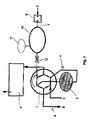
- the sampling device essentially comprises a six-way valve 1 associated with a sample reservoir 2 whose volume corresponds to a dose of sample to be introduced into an analysis cell 3 provided with a vent to perform a test.
- the rotation of the six-way valve 1 shown schematically by the double arrow A causes the displacement of this valve between a circulation position in which it allows the passage of a fluid by the paths schematized in black and a loading position in which it allows the passage of a fluid by the paths schematized in gray.
- the sample reservoir 2 is connected to a transfer circuit 4 schematized in solid lines on the figure 2 which is mounted in shunt on a main pipe not shown.
- the liquid to be analyzed thus enters the transfer circuit 4 via an inlet 5 to exit through an outlet 6.
- the sample reservoir 2 When the six-way valve 1 is in the loading position, the sample reservoir 2 is connected to a filling circuit 7 schematized in solid lines on the figure 3 which connects the analysis cell 3 to a source of compressed gas 8 equipped with a shut-off valve 9.
- the filling circuit 7 further comprises a pneumatic buffer chamber 10 whose volume is adapted to that of the sample reservoir 2.
- the buffer air chamber 10 is mounted upstream of the sample tank 2 in the direction of displacement of the compressed gas.
- the pneumatic buffer chamber 10 is further equipped with a pressure sensor 11.
- a capillary 12 is furthermore mounted between the pneumatic buffer chamber 10 and the sample reservoir 2.
- the liquid to be analyzed circulates continuously in the transfer circuit 4 connected in shunt on the main line between the inlet 5 and the outlet 6 of this circuit.
- the dose of liquid contained in the sample tank 2 is thus constantly renewed.
- a dose of compressed gas is then introduced into the filling circuit and pushes the sample dose contained in the sample volume 2 towards the analysis cell 3.
- the capillary 12 mounted downstream of the pneumatic buffer chamber 10 allows timing this introduction.
- the pressure sensor 11 constantly monitors the pressure in the pneumatic buffer chamber 10 so as to verify that the entire sample dose has actually been transferred to the analysis cell 3.
- control and regulation means make it possible to control a series of unrepresented valves as well as the six-way valve 1 to return it to the circulating position and to allow the continuous circulation of the liquid to be analyzed in the circuit. transfer 4.
Landscapes
- Physics & Mathematics (AREA)
- Health & Medical Sciences (AREA)
- Life Sciences & Earth Sciences (AREA)
- Chemical & Material Sciences (AREA)
- Analytical Chemistry (AREA)
- Biochemistry (AREA)
- General Health & Medical Sciences (AREA)
- General Physics & Mathematics (AREA)
- Immunology (AREA)
- Pathology (AREA)
- Sampling And Sample Adjustment (AREA)
- Automatic Analysis And Handling Materials Therefor (AREA)
Claims (1)
- Verfahren zur automatischen aufeinander folgenden Entnahme einer Serie von Proben von einer in einer Analysezelle zu analysierenden Flüssigkeit über eine Leitungsverbindung aus einer Hauptleitungsanlage, insbesondere aus einer Leitungsanlage einer Einrichtung zur industriellen Herstellung von Erdölprodukten, mit Hilfe einer einen Drehschieber (1) aufweisenden Vorrichtung, der mit einem Probenbehälter (2) mit einem vorgegebenen, der Probenmenge entsprechenden Volumen verbunden ist, die bei jeder Analyse in die Analysezelle (3) eingefüllt werden soll, wobei dieser Drehschieber (1) zwischen zwei Stellungen bewegbar ist, und zwar:- einerseits einer Zirkulationsstellung, in der der Probenbehälter (2) an einen als Umgehungsleitung zur Hauptleitungsanlage installierten Leitungskreis für die Weiterleitung (4) angeschlossen ist, und- andererseits einer Befüllungsstellung, in der der Probenbehälter (2) an einen Leitungskreis zum Befüllen (7) angeschlossen ist, der die Analysezelle (3) mit einer mit einem Absperrventil (9) versehenen Quelle komprimierten Gases (8), insbesondere Stickstoff, verbindet, wobei dieser Leitungskreis zum Befüllen (7) eine pneumatische Pufferkammer (10) mit einem an das Volumen des Probenbehälters (2) angepassten Volumen aufweist, die diesem Behälter (2), in Richtung der Verlagerungsbewegung des komprimierten Gases gesehen, vorgelagert ist, und die mit einem Drucksensor (11) sowie einer zwischen der pneumatische Pufferkammer (10) und dem Probenbehälter (2) angeordneten Kapillare (12) ausgestattet ist,gekennzeichnet durch die Aufeinanderfolge folgender Schritte:- man bringt den Drehschieber (1) in die Zirkulationsstellung,- man lässt einen Strom zu analysierender Flüssigkeit kontinuierlich im Leitungskreis für die Weiterleitung (4) zirkulieren, um die im Probenbehälter (2) enthaltene Flüssigkeit ständig zu erneuern,- man dreht den Drehschieber (1) in die Befüllungsstellung,- man öffnet kurz das Absperrventil (9), damit komprimiertes Gas in den Leitungskreis zum Befüllen (7) einströmt, um die pneumatische Pufferkammer (10) unter Druck zu setzen und daraufhin die in dem Probenbehälter (2) enthaltene Probenmenge zur Analysezelle (3) hin zu drücken, indem der Strom der weitergeleiteten Probe durch das Vorhandensein der Kapillare (12) begrenzt wird,- man überwacht permanent den Druck in der pneumatischen Pufferkammer (10) mit Hilfe eines Drucksensors (11), um zu prüfen, ob die gesamte in dem Probenbehälter (2) enthaltene Probenmenge tatsächlich in die Analysezelle (3) weitergeleitet worden ist, und- man dreht, wenn diese Weiterleitung beendet ist, den Drehschieber (1) in die Zirkulationsstellung, um einen Strom zu analysierender Flüssigkeit kontinuierlich im Leitungskreis für die Weiterleitung (4) zirkulieren zu lassen und so weiter.
Applications Claiming Priority (1)
| Application Number | Priority Date | Filing Date | Title |
|---|---|---|---|
| FR0754354A FR2914749B1 (fr) | 2007-04-06 | 2007-04-06 | Dispositif de prelevement automatique successif en ligne d'une serie d'echantillons d'un liquide a analyser ainsi que procede mis en oeuvre suite a l'utilisation de ce dispositif |
Publications (2)
| Publication Number | Publication Date |
|---|---|
| EP1978368A1 EP1978368A1 (de) | 2008-10-08 |
| EP1978368B1 true EP1978368B1 (de) | 2010-05-12 |
Family
ID=38895672
Family Applications (1)
| Application Number | Title | Priority Date | Filing Date |
|---|---|---|---|
| EP08300117A Active EP1978368B1 (de) | 2007-04-06 | 2008-02-27 | Vorrichtung zur automatischen sukzessiven Online-Entnahme einer Serie von Proben aus einer zu analysierenden Flüssigkeit sowie Umsetzungsverfahren nach dem Einsatz einer solchen Vorrichtung |
Country Status (4)
| Country | Link |
|---|---|
| EP (1) | EP1978368B1 (de) |
| AT (1) | ATE467838T1 (de) |
| DE (1) | DE602008001191D1 (de) |
| FR (1) | FR2914749B1 (de) |
Families Citing this family (3)
| Publication number | Priority date | Publication date | Assignee | Title |
|---|---|---|---|---|
| FR2940440B1 (fr) * | 2008-12-18 | 2010-12-24 | Millipore Corp | Dispositif pour le transfert d'un milieu |
| CN107632099A (zh) * | 2017-08-31 | 2018-01-26 | 天津市鹏翔科技有限公司 | 一种智能在线连续取样自动分析系统及方法 |
| CN112729960B (zh) * | 2021-02-04 | 2025-10-17 | 宁夏福瑞硅烷材料有限公司 | 一种移动式液体密闭取样器 |
Family Cites Families (5)
| Publication number | Priority date | Publication date | Assignee | Title |
|---|---|---|---|---|
| US3918913A (en) * | 1974-12-02 | 1975-11-11 | Lilly Co Eli | Sampler-injector for liquid chromatography |
| US4987785A (en) * | 1990-04-04 | 1991-01-29 | Spencer R Wilson | Constant volume sampling system |
| FR2815413B1 (fr) | 2000-10-17 | 2003-04-04 | Instrumentation Scient De Labo | Procede de determination des caracteristiques de distillation de produits petroliers liquides par mini-distillation express ainsi qu'appareil permettant la mise en oeuvre de ce procede |
| EP1333348A1 (de) * | 2002-02-05 | 2003-08-06 | Avantium International B.V. | Gegendruckregler |
| US7157051B2 (en) * | 2003-09-10 | 2007-01-02 | Advanced Technology Materials, Inc. | Sampling management for a process analysis tool to minimize sample usage and decrease sampling time |
-
2007
- 2007-04-06 FR FR0754354A patent/FR2914749B1/fr active Active
-
2008
- 2008-02-27 AT AT08300117T patent/ATE467838T1/de not_active IP Right Cessation
- 2008-02-27 DE DE602008001191T patent/DE602008001191D1/de active Active
- 2008-02-27 EP EP08300117A patent/EP1978368B1/de active Active
Also Published As
| Publication number | Publication date |
|---|---|
| DE602008001191D1 (de) | 2010-06-24 |
| EP1978368A1 (de) | 2008-10-08 |
| FR2914749A1 (fr) | 2008-10-10 |
| FR2914749B1 (fr) | 2009-07-31 |
| ATE467838T1 (de) | 2010-05-15 |
Similar Documents
| Publication | Publication Date | Title |
|---|---|---|
| EP2936145B1 (de) | Vorrichtung und verfahren zur unterscheidung von gasen in einer probe | |
| EP0184521A1 (de) | Verfahren und Vorrichtung zum Feststellen von Lecken in einem Wärmetauscher während des Betriebes | |
| KR20070006807A (ko) | 흡착제 튜브를 특성화하기 위한 방법 및 시스템 | |
| EP0243284A2 (de) | Künstliche Niere mit einer Anordnung zur Kontrolle der im Dialysatkreislauf fliessenden Flüssigkeitsmengen | |
| EP1978368B1 (de) | Vorrichtung zur automatischen sukzessiven Online-Entnahme einer Serie von Proben aus einer zu analysierenden Flüssigkeit sowie Umsetzungsverfahren nach dem Einsatz einer solchen Vorrichtung | |
| EP3652425B1 (de) | Kraftstoffmessschaltung und verfahren mit kompensation der kraftstoffdichtevariabilität | |
| EP1734351A1 (de) | Vorrichtung und Verfahren zur Untersuchung der undichten Stellen eines Brennkraftgaslagers unter hohen Druck | |
| EP1459007B1 (de) | Vorrichtung zum lagern und mischen von zwei gasen | |
| FR2923014A1 (fr) | Sonde iso-cinetique pour l'analyse de la pollution des gaz generes par un moteur d'avion | |
| FR2531788A1 (fr) | Appareil et procede de regulation de debit | |
| FR2772126A1 (fr) | Procede et dispositif de prelevement isocinetique d'echantillons d'un fluide s'ecoulant dans une tuyauterie | |
| EP0816841A1 (de) | Vorrichtung zum Messen der Löslichkeit fester Bestandteile in überkritischen Fluiden | |
| CH367341A (fr) | Procédé d'analyse chromatographique et appareil pour la mise en oeuvre de ce procédé | |
| WO2014096593A1 (fr) | Debitmetre pour fluide diphasique utilisant un debitmetre massique et une vanne trois voies | |
| EP1884761B1 (de) | Gasentnahme- und -analysesystem | |
| FR2905176A1 (fr) | Dispositif et procede de test d'etancheite d'articles. | |
| FR2817347A1 (fr) | Dispositif de couplage d'un microchromatographe avec un spectrometre de masse et dispositif d'analyse | |
| EP2277016B1 (de) | Verfahren und einrichtung zur bestimmung einer durchflussmessgrösse eines fluides | |
| BE1014782A3 (fr) | Procede de controle de la teneur en hydrocarbures d'une vapeur circulant dans une installation equipee d'un systeme d'aspiration de vapeur. | |
| FR3074232B1 (fr) | Procede de detection d'un defaut d'ecoulement de gaz dans une ligne de ventilation d'un dispositif de purge | |
| FR2970077A1 (fr) | Analyse de fluide circulant dans un conduit | |
| FR2767206A1 (fr) | Generateur de faibles quantites de gaz et procede de generation d'un debit constant de gaz au moyen de ce generateur | |
| EP1978356B1 (de) | Verfahren zur Steuerung der sukzessiven Online-Analyse einer Serie von flüssigen Proben, die in einem Analysekolben zum Sieden gebracht werden | |
| FR3021879A1 (fr) | Dispositif de melange d'un gaz traceur avec un gaz porteur et procede de melange prevoyant un tel dispositif de melange | |
| FR3027999A1 (fr) | Station d'approvisionnement en hydrogene gazeux et procede associe permettant de determiner avec une precision donnee le debit massique d'hydrogene gazeux |
Legal Events
| Date | Code | Title | Description |
|---|---|---|---|
| PUAI | Public reference made under article 153(3) epc to a published international application that has entered the european phase |
Free format text: ORIGINAL CODE: 0009012 |
|
| AK | Designated contracting states |
Kind code of ref document: A1 Designated state(s): AT BE BG CH CY CZ DE DK EE ES FI FR GB GR HR HU IE IS IT LI LT LU LV MC MT NL NO PL PT RO SE SI SK TR |
|
| AX | Request for extension of the european patent |
Extension state: AL BA MK RS |
|
| 17P | Request for examination filed |
Effective date: 20090129 |
|
| AKX | Designation fees paid |
Designated state(s): AT BE BG CH CY CZ DE DK EE ES FI FR GB GR HR HU IE IS IT LI LT LU LV MC MT NL NO PL PT RO SE SI SK TR |
|
| GRAP | Despatch of communication of intention to grant a patent |
Free format text: ORIGINAL CODE: EPIDOSNIGR1 |
|
| GRAS | Grant fee paid |
Free format text: ORIGINAL CODE: EPIDOSNIGR3 |
|
| GRAA | (expected) grant |
Free format text: ORIGINAL CODE: 0009210 |
|
| AK | Designated contracting states |
Kind code of ref document: B1 Designated state(s): AT BE BG CH CY CZ DE DK EE ES FI FR GB GR HR HU IE IS IT LI LT LU LV MC MT NL NO PL PT RO SE SI SK TR |
|
| REG | Reference to a national code |
Ref country code: GB Ref legal event code: FG4D Free format text: NOT ENGLISH |
|
| REG | Reference to a national code |
Ref country code: CH Ref legal event code: EP |
|
| REG | Reference to a national code |
Ref country code: IE Ref legal event code: FG4D Free format text: LANGUAGE OF EP DOCUMENT: FRENCH |
|
| REF | Corresponds to: |
Ref document number: 602008001191 Country of ref document: DE Date of ref document: 20100624 Kind code of ref document: P |
|
| REG | Reference to a national code |
Ref country code: NL Ref legal event code: T3 |
|
| LTIE | Lt: invalidation of european patent or patent extension |
Effective date: 20100512 |
|
| PG25 | Lapsed in a contracting state [announced via postgrant information from national office to epo] |
Ref country code: SE Free format text: LAPSE BECAUSE OF FAILURE TO SUBMIT A TRANSLATION OF THE DESCRIPTION OR TO PAY THE FEE WITHIN THE PRESCRIBED TIME-LIMIT Effective date: 20100512 Ref country code: NO Free format text: LAPSE BECAUSE OF FAILURE TO SUBMIT A TRANSLATION OF THE DESCRIPTION OR TO PAY THE FEE WITHIN THE PRESCRIBED TIME-LIMIT Effective date: 20100812 Ref country code: LT Free format text: LAPSE BECAUSE OF FAILURE TO SUBMIT A TRANSLATION OF THE DESCRIPTION OR TO PAY THE FEE WITHIN THE PRESCRIBED TIME-LIMIT Effective date: 20100512 Ref country code: ES Free format text: LAPSE BECAUSE OF FAILURE TO SUBMIT A TRANSLATION OF THE DESCRIPTION OR TO PAY THE FEE WITHIN THE PRESCRIBED TIME-LIMIT Effective date: 20100823 |
|
| PG25 | Lapsed in a contracting state [announced via postgrant information from national office to epo] |
Ref country code: IS Free format text: LAPSE BECAUSE OF FAILURE TO SUBMIT A TRANSLATION OF THE DESCRIPTION OR TO PAY THE FEE WITHIN THE PRESCRIBED TIME-LIMIT Effective date: 20100912 Ref country code: SI Free format text: LAPSE BECAUSE OF FAILURE TO SUBMIT A TRANSLATION OF THE DESCRIPTION OR TO PAY THE FEE WITHIN THE PRESCRIBED TIME-LIMIT Effective date: 20100512 Ref country code: LV Free format text: LAPSE BECAUSE OF FAILURE TO SUBMIT A TRANSLATION OF THE DESCRIPTION OR TO PAY THE FEE WITHIN THE PRESCRIBED TIME-LIMIT Effective date: 20100512 Ref country code: AT Free format text: LAPSE BECAUSE OF FAILURE TO SUBMIT A TRANSLATION OF THE DESCRIPTION OR TO PAY THE FEE WITHIN THE PRESCRIBED TIME-LIMIT Effective date: 20100512 Ref country code: FI Free format text: LAPSE BECAUSE OF FAILURE TO SUBMIT A TRANSLATION OF THE DESCRIPTION OR TO PAY THE FEE WITHIN THE PRESCRIBED TIME-LIMIT Effective date: 20100512 Ref country code: HR Free format text: LAPSE BECAUSE OF FAILURE TO SUBMIT A TRANSLATION OF THE DESCRIPTION OR TO PAY THE FEE WITHIN THE PRESCRIBED TIME-LIMIT Effective date: 20100512 |
|
| REG | Reference to a national code |
Ref country code: IE Ref legal event code: FD4D |
|
| PG25 | Lapsed in a contracting state [announced via postgrant information from national office to epo] |
Ref country code: CY Free format text: LAPSE BECAUSE OF FAILURE TO SUBMIT A TRANSLATION OF THE DESCRIPTION OR TO PAY THE FEE WITHIN THE PRESCRIBED TIME-LIMIT Effective date: 20100602 Ref country code: PL Free format text: LAPSE BECAUSE OF FAILURE TO SUBMIT A TRANSLATION OF THE DESCRIPTION OR TO PAY THE FEE WITHIN THE PRESCRIBED TIME-LIMIT Effective date: 20100512 |
|
| PG25 | Lapsed in a contracting state [announced via postgrant information from national office to epo] |
Ref country code: DK Free format text: LAPSE BECAUSE OF FAILURE TO SUBMIT A TRANSLATION OF THE DESCRIPTION OR TO PAY THE FEE WITHIN THE PRESCRIBED TIME-LIMIT Effective date: 20100512 Ref country code: IE Free format text: LAPSE BECAUSE OF FAILURE TO SUBMIT A TRANSLATION OF THE DESCRIPTION OR TO PAY THE FEE WITHIN THE PRESCRIBED TIME-LIMIT Effective date: 20100512 Ref country code: EE Free format text: LAPSE BECAUSE OF FAILURE TO SUBMIT A TRANSLATION OF THE DESCRIPTION OR TO PAY THE FEE WITHIN THE PRESCRIBED TIME-LIMIT Effective date: 20100512 |
|
| PG25 | Lapsed in a contracting state [announced via postgrant information from national office to epo] |
Ref country code: CZ Free format text: LAPSE BECAUSE OF FAILURE TO SUBMIT A TRANSLATION OF THE DESCRIPTION OR TO PAY THE FEE WITHIN THE PRESCRIBED TIME-LIMIT Effective date: 20100512 Ref country code: RO Free format text: LAPSE BECAUSE OF FAILURE TO SUBMIT A TRANSLATION OF THE DESCRIPTION OR TO PAY THE FEE WITHIN THE PRESCRIBED TIME-LIMIT Effective date: 20100512 Ref country code: SK Free format text: LAPSE BECAUSE OF FAILURE TO SUBMIT A TRANSLATION OF THE DESCRIPTION OR TO PAY THE FEE WITHIN THE PRESCRIBED TIME-LIMIT Effective date: 20100512 |
|
| PLBE | No opposition filed within time limit |
Free format text: ORIGINAL CODE: 0009261 |
|
| STAA | Information on the status of an ep patent application or granted ep patent |
Free format text: STATUS: NO OPPOSITION FILED WITHIN TIME LIMIT |
|
| 26N | No opposition filed |
Effective date: 20110215 |
|
| PG25 | Lapsed in a contracting state [announced via postgrant information from national office to epo] |
Ref country code: GR Free format text: LAPSE BECAUSE OF FAILURE TO SUBMIT A TRANSLATION OF THE DESCRIPTION OR TO PAY THE FEE WITHIN THE PRESCRIBED TIME-LIMIT Effective date: 20100813 |
|
| REG | Reference to a national code |
Ref country code: DE Ref legal event code: R097 Ref document number: 602008001191 Country of ref document: DE Effective date: 20110214 |
|
| BERE | Be: lapsed |
Owner name: INSTRUMENTATION SCIENTIFIQUE DE LABORATOIRE ISL Effective date: 20110228 |
|
| PG25 | Lapsed in a contracting state [announced via postgrant information from national office to epo] |
Ref country code: MC Free format text: LAPSE BECAUSE OF NON-PAYMENT OF DUE FEES Effective date: 20110228 |
|
| REG | Reference to a national code |
Ref country code: FR Ref legal event code: ST Effective date: 20111102 |
|
| PG25 | Lapsed in a contracting state [announced via postgrant information from national office to epo] |
Ref country code: BE Free format text: LAPSE BECAUSE OF NON-PAYMENT OF DUE FEES Effective date: 20110228 |
|
| PG25 | Lapsed in a contracting state [announced via postgrant information from national office to epo] |
Ref country code: MT Free format text: LAPSE BECAUSE OF FAILURE TO SUBMIT A TRANSLATION OF THE DESCRIPTION OR TO PAY THE FEE WITHIN THE PRESCRIBED TIME-LIMIT Effective date: 20100512 |
|
| PG25 | Lapsed in a contracting state [announced via postgrant information from national office to epo] |
Ref country code: FR Free format text: LAPSE BECAUSE OF NON-PAYMENT OF DUE FEES Effective date: 20110228 |
|
| REG | Reference to a national code |
Ref country code: CH Ref legal event code: PL |
|
| PG25 | Lapsed in a contracting state [announced via postgrant information from national office to epo] |
Ref country code: CH Free format text: LAPSE BECAUSE OF NON-PAYMENT OF DUE FEES Effective date: 20120229 Ref country code: LI Free format text: LAPSE BECAUSE OF NON-PAYMENT OF DUE FEES Effective date: 20120229 |
|
| PG25 | Lapsed in a contracting state [announced via postgrant information from national office to epo] |
Ref country code: LU Free format text: LAPSE BECAUSE OF NON-PAYMENT OF DUE FEES Effective date: 20110227 |
|
| PG25 | Lapsed in a contracting state [announced via postgrant information from national office to epo] |
Ref country code: PT Free format text: LAPSE BECAUSE OF NON-PAYMENT OF DUE FEES Effective date: 20100512 |
|
| PG25 | Lapsed in a contracting state [announced via postgrant information from national office to epo] |
Ref country code: BG Free format text: LAPSE BECAUSE OF FAILURE TO SUBMIT A TRANSLATION OF THE DESCRIPTION OR TO PAY THE FEE WITHIN THE PRESCRIBED TIME-LIMIT Effective date: 20100812 Ref country code: TR Free format text: LAPSE BECAUSE OF FAILURE TO SUBMIT A TRANSLATION OF THE DESCRIPTION OR TO PAY THE FEE WITHIN THE PRESCRIBED TIME-LIMIT Effective date: 20100512 |
|
| PG25 | Lapsed in a contracting state [announced via postgrant information from national office to epo] |
Ref country code: HU Free format text: LAPSE BECAUSE OF FAILURE TO SUBMIT A TRANSLATION OF THE DESCRIPTION OR TO PAY THE FEE WITHIN THE PRESCRIBED TIME-LIMIT Effective date: 20100512 |
|
| P01 | Opt-out of the competence of the unified patent court (upc) registered |
Effective date: 20230527 |
|
| PGFP | Annual fee paid to national office [announced via postgrant information from national office to epo] |
Ref country code: NL Payment date: 20260218 Year of fee payment: 19 |
|
| PGFP | Annual fee paid to national office [announced via postgrant information from national office to epo] |
Ref country code: GB Payment date: 20260218 Year of fee payment: 19 |
|
| PGFP | Annual fee paid to national office [announced via postgrant information from national office to epo] |
Ref country code: DE Payment date: 20260217 Year of fee payment: 19 |
|
| PGFP | Annual fee paid to national office [announced via postgrant information from national office to epo] |
Ref country code: IT Payment date: 20260227 Year of fee payment: 19 |