EP1978537B1 - Contacteur avec un caniveau et branchement de puissance avec un tel contacteur - Google Patents
Contacteur avec un caniveau et branchement de puissance avec un tel contacteur Download PDFInfo
- Publication number
- EP1978537B1 EP1978537B1 EP07006733A EP07006733A EP1978537B1 EP 1978537 B1 EP1978537 B1 EP 1978537B1 EP 07006733 A EP07006733 A EP 07006733A EP 07006733 A EP07006733 A EP 07006733A EP 1978537 B1 EP1978537 B1 EP 1978537B1
- Authority
- EP
- European Patent Office
- Prior art keywords
- additional
- contactor
- central area
- main
- main connector
- Prior art date
- Legal status (The legal status is an assumption and is not a legal conclusion. Google has not performed a legal analysis and makes no representation as to the accuracy of the status listed.)
- Active
Links
Images

Classifications
-
- H—ELECTRICITY
- H01—ELECTRIC ELEMENTS
- H01H—ELECTRIC SWITCHES; RELAYS; SELECTORS; EMERGENCY PROTECTIVE DEVICES
- H01H71/00—Details of the protective switches or relays covered by groups H01H73/00 - H01H83/00
- H01H71/08—Terminals; Connections
-
- H—ELECTRICITY
- H01—ELECTRIC ELEMENTS
- H01H—ELECTRIC SWITCHES; RELAYS; SELECTORS; EMERGENCY PROTECTIVE DEVICES
- H01H71/00—Details of the protective switches or relays covered by groups H01H73/00 - H01H83/00
- H01H71/08—Terminals; Connections
- H01H2071/086—Low power connections for auxiliary switches, e.g. shunt trip
-
- H—ELECTRICITY
- H01—ELECTRIC ELEMENTS
- H01H—ELECTRIC SWITCHES; RELAYS; SELECTORS; EMERGENCY PROTECTIVE DEVICES
- H01H89/00—Combinations of two or more different basic types of electric switches, relays, selectors and emergency protective devices, not covered by any single one of the other main groups of this subclass
- H01H89/06—Combination of a manual reset circuit with a contactor, i.e. the same circuit controlled by both a protective and a remote control device
Definitions
- Such contactors and such load branches are well known. Often, in the contactor main actuators, by means of which the main terminals are actuated, accessible from the edge regions. Furthermore, additional operating elements by means of which the additional terminals can be actuated are often accessible from the central area.
- cables are clamped in the additional terminals of both additional connection areas. At least those additional lines, which are clamped in an additional terminal facing the accessory, must therefore be performed either over the central region and the side facing away from the attachment edge region or on the attachment.
- This approach is disadvantageous because it affects access to the contactor or the attachment and the view of the contactor or the attachment. Furthermore, this embodiment is unaesthetic.
- a low-voltage circuit breaker having a front and a rear wall having housing, the front wall of the rear wall opposite and is formed as an operating side.
- the housing further comprises two side and a bottom and a top surface, which connect the front and the rear wall.
- the side surfaces are on the one hand opposite each other and the bottom and the top surface are on the other hand opposite each other.
- a cable channel is integrated, which extends substantially over the entire width of the low-voltage circuit breaker and in the direction of the housing front wall has one or more passages for passing connecting lines between current transformers and a front electronic trip unit.
- the object of the present invention is to provide a way to avoid the disadvantages mentioned above.
- the object is achieved in a contactor of the type mentioned above in that in the central region a duct is introduced, which extends from the one of the edge regions to the other of the edge regions.
- the object for the load branch described above is achieved in that the contactor is designed as described last and the at least one additional line is guided through the duct.
- the duct runs parallel to the side surfaces. It can be arranged centrally in relation to the side surfaces. Preferably, however, the duct is located closer to one side surface than to the other side surface.
- the duct has one of the side wall facing a channel wall and the other side surface facing channel wall.
- the channel wall facing the other side surface is arranged closer to the one side surface than to the other side surface.
- the contactor has a plunger.
- the plunger is accessible from the central area.
- the plunger is arranged closer to the other side surface than on the one side surface.
- the duct can be covered by a flap. It is possible that the flap covers the duct and other elements - for example, the entire central area. Preferably, however, by means of the flap only the duct can be covered.
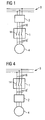
- FIG. 1 has a load feeder on a contactor 1 and an accessory 2.
- the load branch is arranged between a power grid 3 and a load 4.
- the attachment 2 is according to FIG. 1 designed as a circuit breaker. It is upstream of the contactor 1.
- the contactor 1 has a housing 5.
- the housing 5 has a mounting side 6, an operating side 7, two main connection surfaces 8, 8 'and two side surfaces 9, 9'.
- the operator side 7 is opposite to the mounting side 6.
- the main connection surfaces 8, 8 ' are opposite each other.
- the side surfaces 9, 9 ' face each other.
- the operating side 7 has a raised central region 10 and two edge regions 11, 11 'adjoining the middle region 10 on both sides of the middle region 10.
- FIG. 1 Schematically illustrated main terminals 13, 13 ', which are connected to load contacts 14 of the contactor 1, have main receiving openings 15, 15'.
- the main receiving openings 15, 15 ' are main lines 16, 16' insertable.
- the insertability is in this case given by one of the main connection surfaces 8, 8 '.
- the contactor 1 further comprises schematically indicated additional terminals 17, 17 '.
- the additional terminals 17, 17 'additional lines 18, 18' to the contactor 1 can be connected.
- the additional terminals 17, 17' have additional receiving openings 19, 19 ', in which the additional lines 18, 18th 'are insertable.
- the additional lines 18, 18 'are in this case of one of the additional connection surfaces 12, 12' from in the additional receiving openings 19, 19 'insertable.
- main terminals 13, 13 ' are designed as screw terminals.
- main operating elements 20, 20 '(namely screws), by means of which the main clamps 13, 13' are actuated, are accessible from the edge regions 11, 11 '.
- the additional terminals 17, 17 ' are also designed as screw terminals.
- additional operating elements 21, 21 ' (namely screws again), by means of which the additional terminals 17, 17' are actuated, accessible from the central region 10 from.
- the attachment 2 is mechanically and electrically connected to the contactor 1 on one of the main connection surfaces 8, 8 '.
- an intermediate element 22 may be arranged, which causes the electrical and mechanical connection of the auxiliary device 2 with the contactor 1.
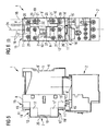
- a duct 23 is introduced, which extends from the one of the edge regions 11, 11 'to the other of the edge regions 11, 11'. Through the duct 23 through at least one of the additional lines 18 is guided, which is clamped in one of the auxiliary device 2 facing additional terminals 17.
- the reference numeral 24 denotes a center line, which runs centrally between the side surfaces 9. As can be seen, the duct 23 extends parallel to the side surfaces 9, but is arranged off-center, namely closer to one side surface 9 than to the other side surface 9 '.
- the duct 23 has two channel walls 25, 25 '.
- the one channel wall 25 faces the one side surface 9, the other channel wall 25 'of the other side surface 9'.
- the other side surface 9 'facing channel wall 25' is arranged closer to the one side surface 9 than on the other side surface 9 '.
- the duct 23 is in the embodiment of FIGS. 2 and 3 thus completely closer to the one side surface 9 arranged as on the other side surface 9 '.
- the duct 23 is preferably coverable by means of a flap 26.
- the conduit 23 can be covered. It would be, however alternatively possible to cover also other elements - in particular the entire central region 10 - with the flap 26.
- the contactor 1 has a plunger 27.
- the plunger 27 is according to FIG. 3 accessible from the central area 10.
- the plunger 27 is in this case arranged closer to the other side surface 9 'than on the one side surface 9. It is thus also arranged off-center.
- an auxiliary device can be actuated, the operator side of the contactor 1 can be attached.
Landscapes
- Switch Cases, Indication, And Locking (AREA)
- Breakers (AREA)
- Multi-Conductor Connections (AREA)
Claims (10)
- Contacteur, construit de la manière suivante :- Il comporte un boîtier (5), ayant un côté montage (6), un côté commande (7), deux faces de raccordement principales (8, 8') et deux faces latérales (9, 9').- Le côté commande (7) fait face au côté montage (6) et est relié au côté montage (6) par les faces de raccordement principales (8, 8') et les faces latérales (9, 9'), les faces de raccordement principales (8, 8') se faisant face et les faces latérales (9, 9') se faisant face.- Le côté commande (7) comporte une zone centrale (10) en relief et deux zones périphériques (11, 11') adjacentes à la zone centrale (10) de part et d'autre de la zone centrale (10), les zones périphériques (11, 11') étant adjacentes aux faces de raccordement principales (8, 8') et reliées à la zone centrale (10) par respectivement une face de raccordement auxiliaire (12, 12').- Des bornes principales (13, 13') reliées à des contacts de puissance (14) du contacteur comportent des ouvertures réceptrices principales (15, 15'), dans lesquelles peuvent s'introduire des conducteurs principaux (16, 16') depuis respectivement une des faces de raccordement principales (8, 8').- Des bornes auxiliaires (17, 17') permettant de brancher des conducteurs auxiliaires (18, 18') sur le contacteur comportent des ouvertures réceptrices auxiliaires (19, 19'), dans lesquelles peuvent s'introduire les conducteurs auxiliaires (18, 18') depuis respectivement une des faces de raccordement auxiliaires (12, 12').- La zone centrale (10) intègre un caniveau (23), s'étendant de l'une des zones périphériques (11, 11') à l'autre des zones périphériques (11, 11').
- Contacteur selon la revendication 1, caractérisé en ce que le caniveau (23) s'étend parallèlement aux faces latérales (9, 9').
- Contacteur selon la revendication 2, caractérisé en ce que le caniveau (23) est placé plus près de ladite une face latérale (9) que de ladite autre face latérale (9').
- Contacteur selon la revendication 3, caractérisé en ce que le caniveau (23) comporte une paroi de caniveau (25) orientée vers ladite une face latérale (9) et une paroi de caniveau (25') orientée vers ladite autre face latérale (9'), et en ce que la paroi de caniveau (25') orientée vers ladite autre face latérale (9') est placée plus près de ladite une face latérale (9) que de ladite autre face latérale (9').
- Contacteur selon la revendication 3 ou la revendication 4, caractérisé en ce que le contacteur comporte un poussoir (27), en ce que le poussoir (27) est accessible depuis la zone centrale (10), et en ce que le poussoir (27) est placé plus près de ladite autre face latérale (9') que de ladite une face latérale (9).
- Contacteur selon l'une des revendications mentionnées ci-dessus, caractérisé en ce que le caniveau (23) peut être recouvert à l'aide d'un volet (26).
- Contacteur selon la revendication 6, caractérisé en ce que le volet (26) permet de recouvrir exclusivement le caniveau (23) .
- Contacteur selon l'une des revendications mentionnées ci-dessus, caractérisé en ce que des actionneurs principaux (20, 20') permettant d'actionner les bornes principales (13, 13') sont accessibles depuis les zones périphériques (11, 11').
- Contacteur selon l'une des revendications mentionnées ci-dessus, caractérisé en ce que des actionneurs auxiliaires (21, 21') permettant d'actionner les bornes auxiliaires (17, 17') sont accessibles depuis la zone centrale (10).
- Branchement de puissance, composé d'un contacteur (1) selon l'une des revendications mentionnées ci-dessus et d'un appareil auxiliaire (2),- dans lequel l'appareil auxiliaire (2) est relié mécaniquement et électriquement au contacteur (1) à l'une des faces de raccordement principales (8, 8'),- dans lequel au moins un conducteur auxiliaire (18, 18') est serré dans l'une des bornes auxiliaires (17, 17') orientées vers l'appareil auxiliaire (2) et guidé à travers le caniveau (23).
Priority Applications (5)
| Application Number | Priority Date | Filing Date | Title |
|---|---|---|---|
| AT07006733T ATE538484T1 (de) | 2007-03-30 | 2007-03-30 | Schütz mit leitungskanal und lastabzweig mit einem derartigen schütz |
| ES07006733T ES2378695T3 (es) | 2007-03-30 | 2007-03-30 | Contactor con canal para conductores y derivación para carga con un tal contactor |
| EP07006733A EP1978537B1 (fr) | 2007-03-30 | 2007-03-30 | Contacteur avec un caniveau et branchement de puissance avec un tel contacteur |
| CN2007101959631A CN101276703B (zh) | 2007-03-30 | 2007-12-07 | 具有导线槽的接触器和具有这种接触器的负荷支路 |
| US12/000,225 US7936241B2 (en) | 2007-03-30 | 2007-12-11 | Contactor with conductor channel and load branch circuit with a contactor of this type |
Applications Claiming Priority (1)
| Application Number | Priority Date | Filing Date | Title |
|---|---|---|---|
| EP07006733A EP1978537B1 (fr) | 2007-03-30 | 2007-03-30 | Contacteur avec un caniveau et branchement de puissance avec un tel contacteur |
Publications (2)
| Publication Number | Publication Date |
|---|---|
| EP1978537A1 EP1978537A1 (fr) | 2008-10-08 |
| EP1978537B1 true EP1978537B1 (fr) | 2011-12-21 |
Family
ID=38190735
Family Applications (1)
| Application Number | Title | Priority Date | Filing Date |
|---|---|---|---|
| EP07006733A Active EP1978537B1 (fr) | 2007-03-30 | 2007-03-30 | Contacteur avec un caniveau et branchement de puissance avec un tel contacteur |
Country Status (5)
| Country | Link |
|---|---|
| US (1) | US7936241B2 (fr) |
| EP (1) | EP1978537B1 (fr) |
| CN (1) | CN101276703B (fr) |
| AT (1) | ATE538484T1 (fr) |
| ES (1) | ES2378695T3 (fr) |
Families Citing this family (3)
| Publication number | Priority date | Publication date | Assignee | Title |
|---|---|---|---|---|
| CN107591289B (zh) * | 2016-07-08 | 2019-12-27 | 浙江正泰电器股份有限公司 | 接触器 |
| FR3075460B1 (fr) * | 2017-12-14 | 2020-01-10 | Schneider Electric Industries Sas | Appareil de protection electrique comportant un systeme d'actionnement pyrotechnique |
| US11581159B2 (en) * | 2019-09-03 | 2023-02-14 | Eaton Intelligent Power Limited | Circuit interrupters with ground fault modules and related methods |
Family Cites Families (16)
| Publication number | Priority date | Publication date | Assignee | Title |
|---|---|---|---|---|
| US3296565A (en) * | 1965-01-06 | 1967-01-03 | Gen Electric | Motor-driven switch operating mechanism with indicating means |
| ATE14489T1 (de) * | 1980-03-13 | 1985-08-15 | Square D Starkstrom Gmbh | Elektromagnetisches schuetz. |
| FR2643503B1 (fr) * | 1989-02-21 | 1991-05-10 | Telemecanique Electrique | Appareil contacteur a interrupteurs proteges |
| JP2566346B2 (ja) * | 1991-06-25 | 1996-12-25 | 松下電工株式会社 | 回路遮断器 |
| JPH05258657A (ja) * | 1992-03-16 | 1993-10-08 | Mitsubishi Electric Corp | 回路しゃ断器 |
| JPH08250013A (ja) * | 1995-03-08 | 1996-09-27 | Toshiba Corp | 漏電遮断器 |
| US5652420A (en) * | 1995-11-14 | 1997-07-29 | Eaton Corporation | Modular contactor control system |
| DE19611997A1 (de) * | 1996-03-26 | 1997-10-02 | Siemens Ag | Elektromagnetisches Relais |
| US5875885A (en) * | 1997-05-28 | 1999-03-02 | Eaton Corporation | Combined wire lead and interphase barrier for power switches |
| DE19729595C1 (de) * | 1997-07-10 | 1998-10-22 | Siemens Ag | Kondensatorschütz |
| US6034584A (en) * | 1997-08-06 | 2000-03-07 | Allen-Bradley Company, Llc | Arrangement for mechanically coupling an overload relay to a contactor |
| DZ2952A1 (fr) * | 1998-12-01 | 2004-03-15 | Schneider Electric Ind Sa | Conacteur électromécanique logeant dans un corps un électroaimant et un porte-contacts mobile. |
| FR2793948B1 (fr) * | 1999-05-20 | 2001-06-29 | Schneider Electric Sa | Relais de protection et ensemble de commande protege a cablage frontal |
| JP2000340093A (ja) * | 1999-05-25 | 2000-12-08 | Fuji Electric Co Ltd | 回路遮断器の過電流引外し装置 |
| DE19958943A1 (de) | 1999-11-26 | 2001-05-31 | Siemens Ag | Niederspannungs-Leistungsschalter mit einem eine Vorderwand und eine Rückwand aufweisenden Gehäuse |
| ES2164593B1 (es) * | 2000-03-17 | 2003-05-16 | Ge Power Controls Iberica S L | Dispositivo de deteccion de fuga a tierra. |
-
2007
- 2007-03-30 AT AT07006733T patent/ATE538484T1/de active
- 2007-03-30 ES ES07006733T patent/ES2378695T3/es active Active
- 2007-03-30 EP EP07006733A patent/EP1978537B1/fr active Active
- 2007-12-07 CN CN2007101959631A patent/CN101276703B/zh active Active
- 2007-12-11 US US12/000,225 patent/US7936241B2/en active Active
Also Published As
| Publication number | Publication date |
|---|---|
| US20080238590A1 (en) | 2008-10-02 |
| ES2378695T3 (es) | 2012-04-17 |
| CN101276703A (zh) | 2008-10-01 |
| US7936241B2 (en) | 2011-05-03 |
| ATE538484T1 (de) | 2012-01-15 |
| EP1978537A1 (fr) | 2008-10-08 |
| CN101276703B (zh) | 2012-04-04 |
Similar Documents
| Publication | Publication Date | Title |
|---|---|---|
| EP2107587B1 (fr) | Adaptateur enfichable pour un appareil de coupure | |
| EP1412957B1 (fr) | Appareil de connexion a module commutateur monobloc | |
| DE102008057754B4 (de) | Baueinheit aus mindestens zwei nebeneinander angeordneten Trennklemmen und mindestens zwei miteinander verbundenen Anschlusssteckern | |
| EP2546856B1 (fr) | Baguette pour fusibles NH | |
| EP2070161A2 (fr) | Appareil de commutation électrique d'une installation | |
| DE102014108090B3 (de) | Adaptersystem mit einem Adapter für Sammelschienen und einem Adapteranschlussmodul | |
| EP1917672B1 (fr) | Systeme de connexion comprenant un appareil de commutation electromagnetique, en particulier un contacteur electromagnetique, et un connecteur | |
| DE102007027522B3 (de) | Schaltgerät | |
| EP2023364B1 (fr) | Commutateur électromagnétique doté de plusieurs zones dégradées les unes par rapport aux autres | |
| EP1978537A1 (fr) | Contacteur avec un caniveau et branchement de puissance avec un tel contacteur | |
| DE20203910U1 (de) | Anschlussmodul der Telekommunikationstechnik | |
| EP1353350B1 (fr) | Interrupteur auxiliaire | |
| DE10061564B4 (de) | Anschlußeinheit für mehrpoligen Schalter | |
| DE10340212B4 (de) | Verteileranordnung | |
| DE102004043466B4 (de) | Strom-Einspeisemodul mit Käfig-Zugfederklemmen | |
| DE69510610T2 (de) | Verbesserungen an Schalter und differential Schalter | |
| DE102022212200B4 (de) | Verdrahtungsmodul zur internen Kontaktierung eines Hilfsschalters, Verdrahtungssystem und Verfahren zum elektrischen Kontaktieren eines solchen Verdrahtungsmoduls | |
| DE10224976A1 (de) | Verbindungsbaugruppe zum elektrischen Verbinden eines elektrischen Grundschaltgeräts mit einem elektrischen Zusatzschaltgerät | |
| DE102020212249B4 (de) | Schaltschrank mit einem Kabelverlegekasten | |
| DE102018132273A1 (de) | Vorrichtung zur Bereitstellung eines Zählerplatzes für einen elektronischen Zähler in einem Zählerschrank und Zählerschrank enthaltend eine solche Vorrichtung. | |
| DE102025146383A1 (de) | Kabelanschlussdose zum Anschluss eines Anschlusskabels und eines Verbindungselements | |
| DE102014118759B4 (de) | Installationsschaltgerät mit zwei Anschlussklemmen unterschiedlichen Typs an einer Gehäuseseite | |
| EP1508949A1 (fr) | Dispositif à fusible basse tension haute puissance | |
| EP3281215B1 (fr) | Système convertisseur de courant et sectionneur équipé d'un tel système | |
| DE102005005081B4 (de) | Kontaktierungsvorrichtung und Verfahren zur Verbindung von elektrischen Leitern, Kontaktelement sowie elektrisches Leitungssystem |
Legal Events
| Date | Code | Title | Description |
|---|---|---|---|
| PUAI | Public reference made under article 153(3) epc to a published international application that has entered the european phase |
Free format text: ORIGINAL CODE: 0009012 |
|
| 17P | Request for examination filed |
Effective date: 20070910 |
|
| AK | Designated contracting states |
Kind code of ref document: A1 Designated state(s): AT BE BG CH CY CZ DE DK EE ES FI FR GB GR HU IE IS IT LI LT LU LV MC MT NL PL PT RO SE SI SK TR |
|
| AX | Request for extension of the european patent |
Extension state: AL BA HR MK RS |
|
| 17Q | First examination report despatched |
Effective date: 20081210 |
|
| AKX | Designation fees paid |
Designated state(s): AT BE BG CH CY CZ DE DK EE ES FI FR GB GR HU IE IS IT LI LT LU LV MC MT NL PL PT RO SE SI SK TR |
|
| GRAP | Despatch of communication of intention to grant a patent |
Free format text: ORIGINAL CODE: EPIDOSNIGR1 |
|
| GRAS | Grant fee paid |
Free format text: ORIGINAL CODE: EPIDOSNIGR3 |
|
| GRAA | (expected) grant |
Free format text: ORIGINAL CODE: 0009210 |
|
| AK | Designated contracting states |
Kind code of ref document: B1 Designated state(s): AT BE BG CH CY CZ DE DK EE ES FI FR GB GR HU IE IS IT LI LT LU LV MC MT NL PL PT RO SE SI SK TR |
|
| REG | Reference to a national code |
Ref country code: GB Ref legal event code: FG4D Free format text: NOT ENGLISH |
|
| REG | Reference to a national code |
Ref country code: CH Ref legal event code: EP |
|
| REG | Reference to a national code |
Ref country code: AT Ref legal event code: REF Ref document number: 538484 Country of ref document: AT Kind code of ref document: T Effective date: 20120115 |
|
| REG | Reference to a national code |
Ref country code: IE Ref legal event code: FG4D |
|
| REG | Reference to a national code |
Ref country code: DE Ref legal event code: R096 Ref document number: 502007008880 Country of ref document: DE Effective date: 20120308 |
|
| REG | Reference to a national code |
Ref country code: NL Ref legal event code: VDEP Effective date: 20111221 |
|
| REG | Reference to a national code |
Ref country code: ES Ref legal event code: FG2A Ref document number: 2378695 Country of ref document: ES Kind code of ref document: T3 Effective date: 20120417 |
|
| PG25 | Lapsed in a contracting state [announced via postgrant information from national office to epo] |
Ref country code: LT Free format text: LAPSE BECAUSE OF FAILURE TO SUBMIT A TRANSLATION OF THE DESCRIPTION OR TO PAY THE FEE WITHIN THE PRESCRIBED TIME-LIMIT Effective date: 20111221 |
|
| LTIE | Lt: invalidation of european patent or patent extension |
Effective date: 20111221 |
|
| PG25 | Lapsed in a contracting state [announced via postgrant information from national office to epo] |
Ref country code: SE Free format text: LAPSE BECAUSE OF FAILURE TO SUBMIT A TRANSLATION OF THE DESCRIPTION OR TO PAY THE FEE WITHIN THE PRESCRIBED TIME-LIMIT Effective date: 20111221 Ref country code: SI Free format text: LAPSE BECAUSE OF FAILURE TO SUBMIT A TRANSLATION OF THE DESCRIPTION OR TO PAY THE FEE WITHIN THE PRESCRIBED TIME-LIMIT Effective date: 20111221 Ref country code: LV Free format text: LAPSE BECAUSE OF FAILURE TO SUBMIT A TRANSLATION OF THE DESCRIPTION OR TO PAY THE FEE WITHIN THE PRESCRIBED TIME-LIMIT Effective date: 20111221 Ref country code: GR Free format text: LAPSE BECAUSE OF FAILURE TO SUBMIT A TRANSLATION OF THE DESCRIPTION OR TO PAY THE FEE WITHIN THE PRESCRIBED TIME-LIMIT Effective date: 20120322 Ref country code: NL Free format text: LAPSE BECAUSE OF FAILURE TO SUBMIT A TRANSLATION OF THE DESCRIPTION OR TO PAY THE FEE WITHIN THE PRESCRIBED TIME-LIMIT Effective date: 20111221 |
|
| PG25 | Lapsed in a contracting state [announced via postgrant information from national office to epo] |
Ref country code: CY Free format text: LAPSE BECAUSE OF FAILURE TO SUBMIT A TRANSLATION OF THE DESCRIPTION OR TO PAY THE FEE WITHIN THE PRESCRIBED TIME-LIMIT Effective date: 20111221 |
|
| REG | Reference to a national code |
Ref country code: IE Ref legal event code: FD4D |
|
| PG25 | Lapsed in a contracting state [announced via postgrant information from national office to epo] |
Ref country code: EE Free format text: LAPSE BECAUSE OF FAILURE TO SUBMIT A TRANSLATION OF THE DESCRIPTION OR TO PAY THE FEE WITHIN THE PRESCRIBED TIME-LIMIT Effective date: 20111221 Ref country code: BG Free format text: LAPSE BECAUSE OF FAILURE TO SUBMIT A TRANSLATION OF THE DESCRIPTION OR TO PAY THE FEE WITHIN THE PRESCRIBED TIME-LIMIT Effective date: 20120321 Ref country code: IS Free format text: LAPSE BECAUSE OF FAILURE TO SUBMIT A TRANSLATION OF THE DESCRIPTION OR TO PAY THE FEE WITHIN THE PRESCRIBED TIME-LIMIT Effective date: 20120421 Ref country code: SK Free format text: LAPSE BECAUSE OF FAILURE TO SUBMIT A TRANSLATION OF THE DESCRIPTION OR TO PAY THE FEE WITHIN THE PRESCRIBED TIME-LIMIT Effective date: 20111221 Ref country code: IE Free format text: LAPSE BECAUSE OF FAILURE TO SUBMIT A TRANSLATION OF THE DESCRIPTION OR TO PAY THE FEE WITHIN THE PRESCRIBED TIME-LIMIT Effective date: 20111221 |
|
| PG25 | Lapsed in a contracting state [announced via postgrant information from national office to epo] |
Ref country code: PL Free format text: LAPSE BECAUSE OF FAILURE TO SUBMIT A TRANSLATION OF THE DESCRIPTION OR TO PAY THE FEE WITHIN THE PRESCRIBED TIME-LIMIT Effective date: 20111221 Ref country code: RO Free format text: LAPSE BECAUSE OF FAILURE TO SUBMIT A TRANSLATION OF THE DESCRIPTION OR TO PAY THE FEE WITHIN THE PRESCRIBED TIME-LIMIT Effective date: 20111221 Ref country code: PT Free format text: LAPSE BECAUSE OF FAILURE TO SUBMIT A TRANSLATION OF THE DESCRIPTION OR TO PAY THE FEE WITHIN THE PRESCRIBED TIME-LIMIT Effective date: 20120423 |
|
| BERE | Be: lapsed |
Owner name: SIEMENS A.G. Effective date: 20120331 |
|
| PLBE | No opposition filed within time limit |
Free format text: ORIGINAL CODE: 0009261 |
|
| STAA | Information on the status of an ep patent application or granted ep patent |
Free format text: STATUS: NO OPPOSITION FILED WITHIN TIME LIMIT |
|
| PG25 | Lapsed in a contracting state [announced via postgrant information from national office to epo] |
Ref country code: DK Free format text: LAPSE BECAUSE OF FAILURE TO SUBMIT A TRANSLATION OF THE DESCRIPTION OR TO PAY THE FEE WITHIN THE PRESCRIBED TIME-LIMIT Effective date: 20111221 Ref country code: MC Free format text: LAPSE BECAUSE OF NON-PAYMENT OF DUE FEES Effective date: 20120331 |
|
| REG | Reference to a national code |
Ref country code: CH Ref legal event code: PL |
|
| 26N | No opposition filed |
Effective date: 20120924 |
|
| REG | Reference to a national code |
Ref country code: DE Ref legal event code: R097 Ref document number: 502007008880 Country of ref document: DE Effective date: 20120924 |
|
| PG25 | Lapsed in a contracting state [announced via postgrant information from national office to epo] |
Ref country code: LI Free format text: LAPSE BECAUSE OF NON-PAYMENT OF DUE FEES Effective date: 20120331 Ref country code: CH Free format text: LAPSE BECAUSE OF NON-PAYMENT OF DUE FEES Effective date: 20120331 Ref country code: BE Free format text: LAPSE BECAUSE OF NON-PAYMENT OF DUE FEES Effective date: 20120331 |
|
| REG | Reference to a national code |
Ref country code: AT Ref legal event code: MM01 Ref document number: 538484 Country of ref document: AT Kind code of ref document: T Effective date: 20120330 |
|
| PG25 | Lapsed in a contracting state [announced via postgrant information from national office to epo] |
Ref country code: FI Free format text: LAPSE BECAUSE OF FAILURE TO SUBMIT A TRANSLATION OF THE DESCRIPTION OR TO PAY THE FEE WITHIN THE PRESCRIBED TIME-LIMIT Effective date: 20111221 |
|
| PG25 | Lapsed in a contracting state [announced via postgrant information from national office to epo] |
Ref country code: MT Free format text: LAPSE BECAUSE OF FAILURE TO SUBMIT A TRANSLATION OF THE DESCRIPTION OR TO PAY THE FEE WITHIN THE PRESCRIBED TIME-LIMIT Effective date: 20111221 Ref country code: AT Free format text: LAPSE BECAUSE OF NON-PAYMENT OF DUE FEES Effective date: 20120330 |
|
| PG25 | Lapsed in a contracting state [announced via postgrant information from national office to epo] |
Ref country code: TR Free format text: LAPSE BECAUSE OF FAILURE TO SUBMIT A TRANSLATION OF THE DESCRIPTION OR TO PAY THE FEE WITHIN THE PRESCRIBED TIME-LIMIT Effective date: 20111221 |
|
| PG25 | Lapsed in a contracting state [announced via postgrant information from national office to epo] |
Ref country code: LU Free format text: LAPSE BECAUSE OF NON-PAYMENT OF DUE FEES Effective date: 20120330 |
|
| PG25 | Lapsed in a contracting state [announced via postgrant information from national office to epo] |
Ref country code: HU Free format text: LAPSE BECAUSE OF FAILURE TO SUBMIT A TRANSLATION OF THE DESCRIPTION OR TO PAY THE FEE WITHIN THE PRESCRIBED TIME-LIMIT Effective date: 20070330 |
|
| REG | Reference to a national code |
Ref country code: FR Ref legal event code: PLFP Year of fee payment: 10 |
|
| REG | Reference to a national code |
Ref country code: FR Ref legal event code: PLFP Year of fee payment: 11 |
|
| REG | Reference to a national code |
Ref country code: FR Ref legal event code: PLFP Year of fee payment: 12 |
|
| REG | Reference to a national code |
Ref country code: DE Ref legal event code: R039 Ref document number: 502007008880 Country of ref document: DE Ref country code: DE Ref legal event code: R008 Ref document number: 502007008880 Country of ref document: DE |
|
| REG | Reference to a national code |
Ref country code: DE Ref legal event code: R040 Ref document number: 502007008880 Country of ref document: DE |
|
| P01 | Opt-out of the competence of the unified patent court (upc) registered |
Effective date: 20230512 |
|
| PGFP | Annual fee paid to national office [announced via postgrant information from national office to epo] |
Ref country code: CZ Payment date: 20240325 Year of fee payment: 18 |
|
| PGFP | Annual fee paid to national office [announced via postgrant information from national office to epo] |
Ref country code: IT Payment date: 20240321 Year of fee payment: 18 Ref country code: FR Payment date: 20240319 Year of fee payment: 18 |
|
| PGFP | Annual fee paid to national office [announced via postgrant information from national office to epo] |
Ref country code: GB Payment date: 20240409 Year of fee payment: 18 |
|
| PGFP | Annual fee paid to national office [announced via postgrant information from national office to epo] |
Ref country code: ES Payment date: 20240627 Year of fee payment: 18 |
|
| PG25 | Lapsed in a contracting state [announced via postgrant information from national office to epo] |
Ref country code: CZ Free format text: LAPSE BECAUSE OF NON-PAYMENT OF DUE FEES Effective date: 20250330 |
|
| GBPC | Gb: european patent ceased through non-payment of renewal fee |
Effective date: 20250330 |
|
| PG25 | Lapsed in a contracting state [announced via postgrant information from national office to epo] |
Ref country code: GB Free format text: LAPSE BECAUSE OF NON-PAYMENT OF DUE FEES Effective date: 20250330 |
|
| PG25 | Lapsed in a contracting state [announced via postgrant information from national office to epo] |
Ref country code: IT Free format text: LAPSE BECAUSE OF NON-PAYMENT OF DUE FEES Effective date: 20250330 Ref country code: FR Free format text: LAPSE BECAUSE OF NON-PAYMENT OF DUE FEES Effective date: 20250331 |
|
| PGFP | Annual fee paid to national office [announced via postgrant information from national office to epo] |
Ref country code: DE Payment date: 20250714 Year of fee payment: 20 |
|
| REG | Reference to a national code |
Ref country code: ES Ref legal event code: FD2A Effective date: 20260505 |