EP1978579A2 - Batterieelektrode und Verfahren zu ihrer Herstellung - Google Patents
Batterieelektrode und Verfahren zu ihrer Herstellung Download PDFInfo
- Publication number
- EP1978579A2 EP1978579A2 EP08102488A EP08102488A EP1978579A2 EP 1978579 A2 EP1978579 A2 EP 1978579A2 EP 08102488 A EP08102488 A EP 08102488A EP 08102488 A EP08102488 A EP 08102488A EP 1978579 A2 EP1978579 A2 EP 1978579A2
- Authority
- EP
- European Patent Office
- Prior art keywords
- current collector
- electrode
- coated
- uncoated
- active material
- Prior art date
- Legal status (The legal status is an assumption and is not a legal conclusion. Google has not performed a legal analysis and makes no representation as to the accuracy of the status listed.)
- Ceased
Links
Images



Classifications
-
- H—ELECTRICITY
- H01—ELECTRIC ELEMENTS
- H01M—PROCESSES OR MEANS, e.g. BATTERIES, FOR THE DIRECT CONVERSION OF CHEMICAL ENERGY INTO ELECTRICAL ENERGY
- H01M4/00—Electrodes
- H01M4/02—Electrodes composed of, or comprising, active material
- H01M4/13—Electrodes for accumulators with non-aqueous electrolyte, e.g. for lithium-accumulators; Processes of manufacture thereof
-
- H—ELECTRICITY
- H01—ELECTRIC ELEMENTS
- H01M—PROCESSES OR MEANS, e.g. BATTERIES, FOR THE DIRECT CONVERSION OF CHEMICAL ENERGY INTO ELECTRICAL ENERGY
- H01M4/00—Electrodes
- H01M4/02—Electrodes composed of, or comprising, active material
- H01M4/04—Processes of manufacture in general
- H01M4/0402—Methods of deposition of the material
- H01M4/0404—Methods of deposition of the material by coating on electrode collectors
-
- H—ELECTRICITY
- H01—ELECTRIC ELEMENTS
- H01M—PROCESSES OR MEANS, e.g. BATTERIES, FOR THE DIRECT CONVERSION OF CHEMICAL ENERGY INTO ELECTRICAL ENERGY
- H01M4/00—Electrodes
- H01M4/02—Electrodes composed of, or comprising, active material
- H01M4/04—Processes of manufacture in general
- H01M4/043—Processes of manufacture in general involving compressing or compaction
-
- H—ELECTRICITY
- H01—ELECTRIC ELEMENTS
- H01M—PROCESSES OR MEANS, e.g. BATTERIES, FOR THE DIRECT CONVERSION OF CHEMICAL ENERGY INTO ELECTRICAL ENERGY
- H01M4/00—Electrodes
- H01M4/02—Electrodes composed of, or comprising, active material
- H01M4/04—Processes of manufacture in general
- H01M4/0471—Processes of manufacture in general involving thermal treatment, e.g. firing, sintering, backing particulate active material, thermal decomposition, pyrolysis
-
- H—ELECTRICITY
- H01—ELECTRIC ELEMENTS
- H01M—PROCESSES OR MEANS, e.g. BATTERIES, FOR THE DIRECT CONVERSION OF CHEMICAL ENERGY INTO ELECTRICAL ENERGY
- H01M4/00—Electrodes
- H01M4/02—Electrodes composed of, or comprising, active material
- H01M4/13—Electrodes for accumulators with non-aqueous electrolyte, e.g. for lithium-accumulators; Processes of manufacture thereof
- H01M4/139—Processes of manufacture
-
- H—ELECTRICITY
- H01—ELECTRIC ELEMENTS
- H01M—PROCESSES OR MEANS, e.g. BATTERIES, FOR THE DIRECT CONVERSION OF CHEMICAL ENERGY INTO ELECTRICAL ENERGY
- H01M4/00—Electrodes
- H01M4/02—Electrodes composed of, or comprising, active material
- H01M4/64—Carriers or collectors
- H01M4/66—Selection of materials
- H01M4/661—Metal or alloys, e.g. alloy coatings
-
- H—ELECTRICITY
- H01—ELECTRIC ELEMENTS
- H01M—PROCESSES OR MEANS, e.g. BATTERIES, FOR THE DIRECT CONVERSION OF CHEMICAL ENERGY INTO ELECTRICAL ENERGY
- H01M10/00—Secondary cells; Manufacture thereof
- H01M10/05—Accumulators with non-aqueous electrolyte
- H01M10/052—Li-accumulators
-
- H—ELECTRICITY
- H01—ELECTRIC ELEMENTS
- H01M—PROCESSES OR MEANS, e.g. BATTERIES, FOR THE DIRECT CONVERSION OF CHEMICAL ENERGY INTO ELECTRICAL ENERGY
- H01M4/00—Electrodes
- H01M4/02—Electrodes composed of, or comprising, active material
- H01M2004/021—Physical characteristics, e.g. porosity, surface area
-
- H—ELECTRICITY
- H01—ELECTRIC ELEMENTS
- H01M—PROCESSES OR MEANS, e.g. BATTERIES, FOR THE DIRECT CONVERSION OF CHEMICAL ENERGY INTO ELECTRICAL ENERGY
- H01M4/00—Electrodes
- H01M4/02—Electrodes composed of, or comprising, active material
- H01M4/13—Electrodes for accumulators with non-aqueous electrolyte, e.g. for lithium-accumulators; Processes of manufacture thereof
- H01M4/131—Electrodes based on mixed oxides or hydroxides, or on mixtures of oxides or hydroxides, e.g. LiCoOx
-
- H—ELECTRICITY
- H01—ELECTRIC ELEMENTS
- H01M—PROCESSES OR MEANS, e.g. BATTERIES, FOR THE DIRECT CONVERSION OF CHEMICAL ENERGY INTO ELECTRICAL ENERGY
- H01M4/00—Electrodes
- H01M4/02—Electrodes composed of, or comprising, active material
- H01M4/13—Electrodes for accumulators with non-aqueous electrolyte, e.g. for lithium-accumulators; Processes of manufacture thereof
- H01M4/139—Processes of manufacture
- H01M4/1391—Processes of manufacture of electrodes based on mixed oxides or hydroxides, or on mixtures of oxides or hydroxides, e.g. LiCoOx
-
- Y—GENERAL TAGGING OF NEW TECHNOLOGICAL DEVELOPMENTS; GENERAL TAGGING OF CROSS-SECTIONAL TECHNOLOGIES SPANNING OVER SEVERAL SECTIONS OF THE IPC; TECHNICAL SUBJECTS COVERED BY FORMER USPC CROSS-REFERENCE ART COLLECTIONS [XRACs] AND DIGESTS
- Y02—TECHNOLOGIES OR APPLICATIONS FOR MITIGATION OR ADAPTATION AGAINST CLIMATE CHANGE
- Y02E—REDUCTION OF GREENHOUSE GAS [GHG] EMISSIONS, RELATED TO ENERGY GENERATION, TRANSMISSION OR DISTRIBUTION
- Y02E60/00—Enabling technologies; Technologies with a potential or indirect contribution to GHG emissions mitigation
- Y02E60/10—Energy storage using batteries
-
- Y—GENERAL TAGGING OF NEW TECHNOLOGICAL DEVELOPMENTS; GENERAL TAGGING OF CROSS-SECTIONAL TECHNOLOGIES SPANNING OVER SEVERAL SECTIONS OF THE IPC; TECHNICAL SUBJECTS COVERED BY FORMER USPC CROSS-REFERENCE ART COLLECTIONS [XRACs] AND DIGESTS
- Y02—TECHNOLOGIES OR APPLICATIONS FOR MITIGATION OR ADAPTATION AGAINST CLIMATE CHANGE
- Y02P—CLIMATE CHANGE MITIGATION TECHNOLOGIES IN THE PRODUCTION OR PROCESSING OF GOODS
- Y02P70/00—Climate change mitigation technologies in the production process for final industrial or consumer products
- Y02P70/50—Manufacturing or production processes characterised by the final manufactured product
Definitions
- the present invention relates to an electrode for a battery. More particularly, the present invention relates to a current collector used for an electrode of a secondary battery.
- a secondary battery used as a power source for electronic appliances has an electrode unit that includes an anode, a cathode, and a separator disposed between the anode and the cathode.
- Each of the anode and the cathode is structured by coating an active material on a current collector formed of metal.
- the current collector of the anode is formed of copper or aluminum and coated with a carbon-based active material.
- the current collector of the cathode is formed of aluminum and coated with an active material, such as LiCoO 2 , LiMnO 2 , or LiNiO 2 .
- the active material is coated in a slurry form together with materials, such as a conductive agent, a binder, a solvent, and the like so that it can be effectively coated on the current collector.
- the current collector coated with the active material slurry is dried in a drying furnace, after which the current collector is pressed flat by a pressing machine, for example.
- the electrode When pressing the current collector, the electrode may be bent such that a defect occurs during a winding process of the electrode. As a result, productivity is reduced, as is charge and discharge efficiency.
- the present invention has been made in an effort to provide a secondary battery having an electrode that is designed to minimize a difference between an amount of elongation of a part coated with an active material and an uncoated part not coated with an active material.
- an electrode for a battery includes a thin plate current collector and an active material layer coated on the current collector.
- the current collector is provided at a top surface with a coated current collector part and an uncoated current collector part adjacent to the coated current collector part.
- the uncoated current collector part has a yield stress that is less than that of the coated current collector part.
- a method of fabricating an electrode includes forming a current collector, annealing an edge of the current collector, coating an active material on the current collector, and pressing the current collector on which the active material has been coated.
- the uncoated current collector part may have greater elongation ratio than that of the coated current collector part.
- the uncoated current collector part may have less residual stress than that of the coated current collector part.
- the condition of 1.5 ⁇ 1/ ⁇ 2 ⁇ 7 may be satisfied.
- the current collector may be formed of aluminum.
- the current collector may be formed of copper.
- the battery may be fabricated by a positive electrode and a negative electrode that are stacked on one another with a separator interposed therebetween, and then the positive electrode, the negative electrode, and the separator are rolled up.
- the annealing of the edge may be performed before the active material is coated.
- the annealing of the edge may be performed after the active material has been coated.
- the current collector may be heated by radiant heat.
- FIG. 1 is a perspective view of an electrode for a battery according to an exemplary embodiment of the present invention.
- An electrode 10 used as a positive electrode or negative electrode of a rechargeable battery includes a current collector 15 and an active material layer 17 formed on the current collector 15.
- the active material layer 17 is not formed on an entire surface of the current collector 15. That is, the electrode 10 has a part 12 coated with an active material and an uncoated part 11 not coated with an active material, thereby exposing the current collector 15.
- the current collector 15 is formed of aluminum when the electrode 10 is used as a positive electrode, while the current collector 15 is formed of copper or aluminum when the electrode 10 is used as a negative electrode.
- the active material layer 17 is formed of a slurry including an active material, such as LiCoO 2 , LiMnO 2 , or LiNiO 2 , a conductive agent, and a binder.
- the active material layer 17 is formed of a slurry including a carbon-based material, a conductive agent, and a binder.
- the current collector 15 is provided in a strip configuration extending in a direction, and the uncoated part 11 is formed along a longitudinal edge of the current collector 15.
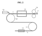
- An apparatus for manufacturing the electrode 10 for a battery includes a heating member 110 that is installed at an extreme end to heat the current collector 15, a plurality of rollers 121 and 123 for transferring the current collector 15, an active material coating member 130 installed adjacent to the roller 123, a drying furnace 140 for drying the current collector 15 on which the active material layer 17 is formed, and a pressing member 150 for pressing the dried current collector 15.
- An edge of the current collector 15 is heated by the heating member 110 installed at the extreme end (of the apparatus), and subsequently, the current collector 15 is transferred toward the coating member 130 by the rollers 121 and 123. Since the heated part of the current collector 15 is slowly cooled while being transferred toward the coating member 130, the edge of the current collector 15 is annealed and thus yield stress and residual stress thereof decrease while an elongation ratio thereof increases.
- a cooling time is controlled by a length of path between the heating member 110 and the coating member 130.
- a cooling method described above is provided only by way of example and thus a cooling method of the present invention is not limited to the above configuration.
- two heating members 110 are installed to correspond to both longitudinal edges of the current collector 15.
- the heating members 110 are configured to heat the current collector 15 using radiant heat. When the current collector 15 is heated by radiant heat, specific portions can be heated efficiently.
- the heating member 110 is provided only by way of example and thus the heating member 110 of the present invention is not limited to the above configuration.
- the heating member 110 may be configured to heat the current collector 115 through conduction, convection, etc.
- the cooled current collector 15 is transferred to the roller 123 installed adjacent to the coating member 130 and coated with the active material layer 17 by the coating member 130.
- the current collector 15 coated with the active material layer 17 is transferred to the drying furnace 140 so that volatile ingredients contained in the active material layer 17 can be evaporated.
- the current collector 15 that is dried in the drying furnace 140 is then pressed flat by the pressing member 150.
- FIG. 2 shows one side of current collector 15 is coated with the active material. But the electrode 10 shown in FIG. 2 is provided only by way of example and thus both side of current collector may be coated with the active material.
- the current collector 15 is cut along a center thereof in a width direction and completed as the electrode 10 as shown in FIG. 1 .
- the electrode 10 is used as a positive electrode or a negative electrode of a battery.
- the positive electrode and the negative electrode are stacked on one another with a separator interposed therebetween, and then the stacked positive electrode, negative electrode, and separator are rolled up to form a jelly-roll electrode assembly.
- FIG. 4 is a perspective view of a current collector according to an exemplary embodiment of the present invention.
- FIG. 4 shows the current collector 15 including a coated current collector part 15b and an uncoated current collector part 15a formed at an edge of current collector 15.
- the current collector 15 is annealed as described above, and thus, with reference to FIG. 4 , the elongation ratio of the uncoated current collector part 15a becomes greater than that of the coated current collector part 15b.
- the yield stress of the uncoated current collector part 15a becomes smaller than that of the coated current collector part 15b.
- the condition of 1.5 ⁇ 1/ ⁇ 2 ⁇ 7 is satisfied.
- ⁇ 1/ ⁇ 2 is less than 1.5, the uncoated current collector part 15a is not sufficiently elongated during the pressing process and thus the electrode 10 may be bent.
- ⁇ 1/ ⁇ 2 is greater than 7, the uncoated current collector part 15a is heated to an excessively high temperature, such that the structure of the uncoated current collector part 15a may be damaged.
- An uncoated current collector part 15a of a positive current collector 15 formed of A1 A1050 and having a thickness of 15 ⁇ m is annealed.
- the annealing process includes heating the positive current collector 15 to 550°C for 24 seconds and slowly cooling the anode current collector 15 to room temperature.
- the current collector 15 is coated with an active material on a coated current collector part 15b and dried and pressed.
- a yield load and an elongation amount of the annealed uncoated current collector part 15 are measured by a tensile test. In the tensile test, a specimen is formed of the annealed uncoated current collector part 15a that has a width of 3mm and a length of 10mm.
- a positive current collector formed of the A1 A1050 and having a thickness of 15 ⁇ m is coated with an active material on a coated current collector part, and the positive current collector is dried and pressed.
- a yield load and an amount of elongation of an uncoated current collector part are measured by a tensile test.
- a specimen is formed of the uncoated current collector part that has a width of 3mm and a length of 10mm.
- Yield load and an amount of elongation of the coated current collector part and the uncoated current collector part are measured by a tensile test.
- a specimen is formed of the coated current collector part where active material is removed and the specimen has a width of 3mm and a length of 10mm.
- the yield load of the uncoated current collector part is greater than that of the coated current collector part.
- the elongation amount of the coated current collector part is greater than that of the uncoated collector part.
- the yield load of the uncoated current collector part 15a is significantly less than that of the coated current collector part 15b.
- the elongation amount of the uncoated current collector part 15a is about twice that of the coated current collector part 15b.
- a yield load ratio of the yield load of the coated current collector part to the yield load of the conventional uncoated current collector part is 0.948.
- a yield load ratio of the yield load of the coated current collector part 15b to the yield load of the uncoated current collector part 15a is 4.555.
- the yield load ratio is greater than 1.
- the uncoated current collector part 15a since the uncoated current collector part 15a is annealed, the softness of the uncoated current collector part 15a significantly increases and the yield load becomes significantly less than the uncoated current collector part of the conventional current collector.
- the uncoated current collector part 15a of the present invention has smaller yield stress than the coated current collector part 15b, and further, has much smaller yield stress than the conventional uncoated current collector.
- a ratio of an amount of elongation of the coated current collector part to an amount of elongation of the uncoated current collector part is 1.078.
- a ratio of an amount of elongation of the coated current collector part 15b to an amount of elongation of the uncoated current collector part 15a is 0.512. That is, it can be noted that, for the current collector 15 of the present invention, the amount of elongation of the uncoated current collector part 15a is significantly greater than that of the coated current collector part 15b.
- the elongation ratio of the uncoated current collector part 15a is greater than that of the coated current collector part 15b.
- the uncoated current collector part 15a of the current collector 15 of the present invention since the uncoated current collector part 15a of the current collector 15 of the present invention has a relatively high amount of elongation even under a relatively small load, the uncoated current collector part 15a is sufficiently elongated even when a relatively high pressure is applied to the coated current collector part 15b to elongate the coated current collector part 15b. Therefore, the bending of the electrode 10, which is caused by the amount of elongation difference between the coated current collector part 15b and the uncoated current collector part 15a, can be prevented.
- FIG. 6 is a plain view of a current collector according to an exemplary embodiment of the present invention.
- the uncoated current collector part 15a is located at width direction end of current collector part 15 and has a width 35mm.
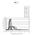
- Points shown in FIG. 6 are locations of specimens for measuring yield load and elongation amount. Points are appointed at 10mm intervals for showing the difference of yield load between the annealed part and the not annealed part.
- a specimen is picked that has a width of 3.18mm and a length of 9.53mm, and a tensile test performed on the specimens.
- FIG. 7 shows result of the tensile test. As shown in FIG. 7 , from P1 to P3 located in the annealed part have a relatively small yield load and a relatively large elongation amount, from P4 to P8 located in the not annealed part have a relatively large yield load and a relatively small elongation amount.
- the annealed part is easily elongated at small load, and the not annealed part is not easily elongated at large load.
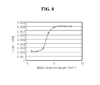
- FIG. 8 shows yield load distribution along width direction of a current collector. Referring to FIG. 8 , between P3 located in the annealed part and P4 located in the not annealed part, the yield load changes significantly.
- the uncoated current collector part is annealed to reduce the yield stress thereof, the uncoated current collector part can be effectively elongated and thus the bending of the electrode during the pressing process can be prevented. Accordingly, the structural stability and the productivity of the electrode can be enhanced.
Landscapes
- Chemical & Material Sciences (AREA)
- Engineering & Computer Science (AREA)
- Chemical Kinetics & Catalysis (AREA)
- Electrochemistry (AREA)
- General Chemical & Material Sciences (AREA)
- Manufacturing & Machinery (AREA)
- Materials Engineering (AREA)
- Battery Electrode And Active Subsutance (AREA)
- Cell Electrode Carriers And Collectors (AREA)
- Secondary Cells (AREA)
Applications Claiming Priority (1)
| Application Number | Priority Date | Filing Date | Title |
|---|---|---|---|
| KR1020070026724A KR100823198B1 (ko) | 2007-03-19 | 2007-03-19 | 전지용 전극 및 전지용 전극의 제조 방법 |
Publications (2)
| Publication Number | Publication Date |
|---|---|
| EP1978579A2 true EP1978579A2 (de) | 2008-10-08 |
| EP1978579A3 EP1978579A3 (de) | 2012-08-29 |
Family
ID=39571865
Family Applications (1)
| Application Number | Title | Priority Date | Filing Date |
|---|---|---|---|
| EP08102488A Ceased EP1978579A3 (de) | 2007-03-19 | 2008-03-11 | Batterieelektrode und Verfahren zu ihrer Herstellung |
Country Status (5)
| Country | Link |
|---|---|
| US (1) | US20080233476A1 (de) |
| EP (1) | EP1978579A3 (de) |
| JP (1) | JP5001867B2 (de) |
| KR (1) | KR100823198B1 (de) |
| CN (1) | CN101271970B (de) |
Cited By (2)
| Publication number | Priority date | Publication date | Assignee | Title |
|---|---|---|---|---|
| EP2680346A4 (de) * | 2011-02-23 | 2015-09-02 | Toshiba Kk | Sekundärbatterie mit nichtwässrigem elektrolyt |
| DE102017215143A1 (de) * | 2017-08-30 | 2019-02-28 | Bayerische Motoren Werke Aktiengesellschaft | Elektrode und verfahren zur ihrer herstellung |
Families Citing this family (22)
| Publication number | Priority date | Publication date | Assignee | Title |
|---|---|---|---|---|
| US8894818B2 (en) * | 2008-02-28 | 2014-11-25 | Chevron U.S.A. Inc. | Process for generating a hydrocarbon feedstock lignin |
| KR20100069493A (ko) * | 2008-12-16 | 2010-06-24 | 삼성전자주식회사 | 전지 및 그를 포함하는 전지팩 |
| US20110052954A1 (en) * | 2009-02-24 | 2011-03-03 | Panasonic Corporation | Battery, method of manufacturing the same and non-aqueous secondary battery using the same |
| KR20110017761A (ko) * | 2009-08-14 | 2011-02-22 | 에스비리모티브 주식회사 | 이차 전지용 전극판 및 이를 포함하는 이차 전지 |
| JP5716622B2 (ja) * | 2011-09-26 | 2015-05-13 | 日産自動車株式会社 | 帯状電極の製造装置および製造方法 |
| US20130189577A1 (en) * | 2011-12-20 | 2013-07-25 | Zheng Wang | Apparatus and method for hot coating electrodes of lithium-ion batteries |
| JP5765574B2 (ja) * | 2011-12-20 | 2015-08-19 | トヨタ自動車株式会社 | 二次電池及びその製造方法ならびに該電池に用いられる負極シートの製造方法 |
| US10050255B2 (en) | 2012-03-08 | 2018-08-14 | Samsung Sdi Co., Ltd. | Rechargeable battery and method of manufacturing the same |
| US9490472B2 (en) * | 2013-03-28 | 2016-11-08 | Semiconductor Energy Laboratory Co., Ltd. | Method for manufacturing electrode for storage battery |
| WO2019239988A1 (ja) * | 2018-06-11 | 2019-12-19 | 株式会社村田製作所 | 電池用電極およびその製造方法 |
| KR102751961B1 (ko) | 2018-11-20 | 2025-01-10 | 주식회사 엘지에너지솔루션 | 전극 조립체 제조장치 및 전극 조립체 제조방법 |
| US12261282B2 (en) | 2019-12-05 | 2025-03-25 | Lg Energy Solution, Ltd. | Electrode for secondary battery and method of manufacturing electrode for secondary battery |
| US12230842B2 (en) | 2020-11-06 | 2025-02-18 | Sk On Co., Ltd. | Electrode for lithium secondary battery and method of manufacturing the same |
| KR20220079083A (ko) * | 2020-12-04 | 2022-06-13 | 주식회사 엘지화학 | 전극 압연 장치 및 전극 압연 방법 |
| KR20220079084A (ko) * | 2020-12-04 | 2022-06-13 | 주식회사 엘지화학 | 전극 압연 장치 및 전극 압연 방법 |
| JP7178433B2 (ja) * | 2021-01-19 | 2022-11-25 | 本田技研工業株式会社 | 非水電解質二次電池用負極及びこれを備える非水電解質二次電池 |
| JP7289861B2 (ja) * | 2021-02-24 | 2023-06-12 | プライムプラネットエナジー&ソリューションズ株式会社 | 電極シートの製造方法 |
| WO2024020730A1 (zh) * | 2022-07-25 | 2024-02-01 | 宁德时代新能源科技股份有限公司 | 集流体、极片、电池单体、电池及用电装置 |
| CN120035894A (zh) * | 2022-11-01 | 2025-05-23 | 株式会社Lg新能源 | 电极片材加热装置、电极片材加热方法以及卷绕型电极组件 |
| KR20240102415A (ko) * | 2022-12-26 | 2024-07-03 | 주식회사 엘지에너지솔루션 | 알루미늄 박막의 제조 방법, 알루미늄 박막, 이를 포함하는 양극 및 리튬 이차 전지 |
| KR20250053476A (ko) | 2023-10-13 | 2025-04-22 | 주식회사 엘지에너지솔루션 | 롤 검사 방법 |
| KR102915650B1 (ko) * | 2024-12-19 | 2026-01-20 | 김경환 | 고율충전용 이차전지의 음극 제조방법 |
Citations (1)
| Publication number | Priority date | Publication date | Assignee | Title |
|---|---|---|---|---|
| JP2000251942A (ja) * | 1999-03-01 | 2000-09-14 | Matsushita Battery Industrial Co Ltd | 非水電解液二次電池の製造方法 |
Family Cites Families (16)
| Publication number | Priority date | Publication date | Assignee | Title |
|---|---|---|---|---|
| CA2103490A1 (en) * | 1992-11-24 | 1994-05-25 | John J. Weckesser | Metal hydride electrode, cell and process |
| JPH09199166A (ja) * | 1996-01-16 | 1997-07-31 | Hitachi Ltd | ナトリウム2次電池 |
| JP3986727B2 (ja) * | 2000-05-09 | 2007-10-03 | 株式会社タクマ | 導電性ウェブ状材料の製造装置及びこれを用いた導電性ウェブ状材料の製造方法 |
| US6827796B2 (en) * | 2000-11-02 | 2004-12-07 | Composite Tool Company, Inc. | High strength alloys and methods for making same |
| JP2003133878A (ja) * | 2001-10-29 | 2003-05-09 | Sumitomo Special Metals Co Ltd | 圧電素子の製造方法 |
| JP3960877B2 (ja) * | 2002-08-05 | 2007-08-15 | 三洋電機株式会社 | 電池の製造方法 |
| JP2004071335A (ja) | 2002-08-06 | 2004-03-04 | Matsushita Electric Ind Co Ltd | 電池用電極板、電池、電池用電極板の製造方法、および電池用電極板の製造装置 |
| US8021778B2 (en) * | 2002-08-09 | 2011-09-20 | Infinite Power Solutions, Inc. | Electrochemical apparatus with barrier layer protected substrate |
| US6878458B2 (en) * | 2002-09-12 | 2005-04-12 | Matsushita Electric Industrial Co., Ltd. | Metal foil for current collector of secondary battery and method of producing the same |
| JP4357825B2 (ja) * | 2002-10-04 | 2009-11-04 | パナソニック株式会社 | 電池用正極板およびその製造方法ならびに二次電池 |
| JP4238630B2 (ja) * | 2003-05-09 | 2009-03-18 | 株式会社デンソー | 電極の製造方法 |
| JP2005093236A (ja) * | 2003-09-17 | 2005-04-07 | Toyota Motor Corp | シート電極の製造方法 |
| KR100560492B1 (ko) * | 2004-02-25 | 2006-03-13 | 삼성에스디아이 주식회사 | 리튬 이차 전지용 양극 전류 집전체 및 이를 포함하는리튬 이차 전지 |
| JP2006147485A (ja) | 2004-11-24 | 2006-06-08 | Ngk Spark Plug Co Ltd | 蓄電装置の製造方法 |
| JP4954585B2 (ja) * | 2006-03-31 | 2012-06-20 | 株式会社デンソー | リチウムイオン電池用電極の製造方法 |
| JP2007305322A (ja) * | 2006-05-09 | 2007-11-22 | Toyota Motor Corp | 電池及びその製造方法 |
-
2007
- 2007-03-19 KR KR1020070026724A patent/KR100823198B1/ko active Active
-
2008
- 2008-01-15 JP JP2008006044A patent/JP5001867B2/ja active Active
- 2008-01-30 US US12/010,868 patent/US20080233476A1/en not_active Abandoned
- 2008-03-03 CN CN2008100831160A patent/CN101271970B/zh active Active
- 2008-03-11 EP EP08102488A patent/EP1978579A3/de not_active Ceased
Patent Citations (1)
| Publication number | Priority date | Publication date | Assignee | Title |
|---|---|---|---|---|
| JP2000251942A (ja) * | 1999-03-01 | 2000-09-14 | Matsushita Battery Industrial Co Ltd | 非水電解液二次電池の製造方法 |
Cited By (3)
| Publication number | Priority date | Publication date | Assignee | Title |
|---|---|---|---|---|
| EP2680346A4 (de) * | 2011-02-23 | 2015-09-02 | Toshiba Kk | Sekundärbatterie mit nichtwässrigem elektrolyt |
| US9142831B2 (en) | 2011-02-23 | 2015-09-22 | Kabushiki Kaisha Toshiba | Nonaqueous electrolyte secondary battery |
| DE102017215143A1 (de) * | 2017-08-30 | 2019-02-28 | Bayerische Motoren Werke Aktiengesellschaft | Elektrode und verfahren zur ihrer herstellung |
Also Published As
| Publication number | Publication date |
|---|---|
| EP1978579A3 (de) | 2012-08-29 |
| CN101271970A (zh) | 2008-09-24 |
| KR100823198B1 (ko) | 2008-04-18 |
| JP5001867B2 (ja) | 2012-08-15 |
| JP2008235251A (ja) | 2008-10-02 |
| US20080233476A1 (en) | 2008-09-25 |
| CN101271970B (zh) | 2010-08-25 |
Similar Documents
| Publication | Publication Date | Title |
|---|---|---|
| EP1978579A2 (de) | Batterieelektrode und Verfahren zu ihrer Herstellung | |
| EP2296209B1 (de) | Elektrodenplatte für eine Sekundärbatterie und Sekundärbatterie damit | |
| KR101175031B1 (ko) | 전극판 제조 방법 및 이 방법으로 제조된 전극판 | |
| KR101744086B1 (ko) | 이차 전지 및 이차 전지의 제조 방법 | |
| JP7482429B2 (ja) | 電極の製造方法 | |
| KR20120055650A (ko) | 전극 스택을 제조하기 위한 방법 | |
| US10381650B2 (en) | Cladding material for battery collector and electrode | |
| US20160056420A1 (en) | Rechargeable battery and method of manufacturing the same | |
| JP6838480B2 (ja) | 電極の製造方法 | |
| JP2011023129A (ja) | 非水系二次電池用正極板の製造方法およびその製造装置 | |
| JP3683134B2 (ja) | シート電極の製造方法 | |
| EP4053955A1 (de) | Verfahren zur herstellung eines elektrochemischen energiespeicherelements | |
| JP5724930B2 (ja) | 蓄電装置及び二次電池並びに蓄電装置の製造方法 | |
| JP2005093236A (ja) | シート電極の製造方法 | |
| JP2014143008A (ja) | リチウムイオン二次電池の負極集電体用銅箔、及びリチウムイオン二次電池の負極の製造方法、並びにリチウムイオン二次電池の負極集電体用銅箔の評価方法 | |
| EP4095938B1 (de) | Sekundärbatterie | |
| EP4466747B1 (de) | Verfahren und vorrichtung zur thermischen trocknungsbehandlung von elektroden-separator-verbünden mittels induktion | |
| US20240332631A1 (en) | Method for manufacturing non-aqueous secondary battery and device for manufacturing non-aqueous secondary battery | |
| US20260100396A1 (en) | Method for manufacturing battery | |
| CN118588856A (zh) | 用于电化学的蓄能器元件的带形的电极 | |
| KR20250088882A (ko) | 리튬 이차전지용 전극 및 이의 제조방법 | |
| KR20250041899A (ko) | 전극 조립체의 제조 장치 및 전극 조립체의 제조 방법 |
Legal Events
| Date | Code | Title | Description |
|---|---|---|---|
| PUAI | Public reference made under article 153(3) epc to a published international application that has entered the european phase |
Free format text: ORIGINAL CODE: 0009012 |
|
| 17P | Request for examination filed |
Effective date: 20080311 |
|
| AK | Designated contracting states |
Kind code of ref document: A2 Designated state(s): AT BE BG CH CY CZ DE DK EE ES FI FR GB GR HR HU IE IS IT LI LT LU LV MC MT NL NO PL PT RO SE SI SK TR |
|
| AX | Request for extension of the european patent |
Extension state: AL BA MK RS |
|
| RAP1 | Party data changed (applicant data changed or rights of an application transferred) |
Owner name: SAMSUNG SDI CO., LTD. |
|
| PUAL | Search report despatched |
Free format text: ORIGINAL CODE: 0009013 |
|
| AK | Designated contracting states |
Kind code of ref document: A3 Designated state(s): AT BE BG CH CY CZ DE DK EE ES FI FR GB GR HR HU IE IS IT LI LT LU LV MC MT NL NO PL PT RO SE SI SK TR |
|
| AX | Request for extension of the european patent |
Extension state: AL BA MK RS |
|
| RIC1 | Information provided on ipc code assigned before grant |
Ipc: H01M 10/052 20100101ALI20120726BHEP Ipc: H01M 4/13 20100101ALI20120726BHEP Ipc: H01M 4/66 20060101ALI20120726BHEP Ipc: H01M 4/02 20060101AFI20120726BHEP Ipc: H01M 4/139 20100101ALI20120726BHEP Ipc: H01M 4/04 20060101ALI20120726BHEP |
|
| AKX | Designation fees paid |
Designated state(s): DE FR GB |
|
| 17Q | First examination report despatched |
Effective date: 20130516 |
|
| RAP1 | Party data changed (applicant data changed or rights of an application transferred) |
Owner name: SAMSUNG SDI CO., LTD. |
|
| STAA | Information on the status of an ep patent application or granted ep patent |
Free format text: STATUS: THE APPLICATION HAS BEEN REFUSED |
|
| 18R | Application refused |
Effective date: 20151216 |