EP1978647A2 - Système de réception à large bande - Google Patents
Système de réception à large bande Download PDFInfo
- Publication number
- EP1978647A2 EP1978647A2 EP08004533A EP08004533A EP1978647A2 EP 1978647 A2 EP1978647 A2 EP 1978647A2 EP 08004533 A EP08004533 A EP 08004533A EP 08004533 A EP08004533 A EP 08004533A EP 1978647 A2 EP1978647 A2 EP 1978647A2
- Authority
- EP
- European Patent Office
- Prior art keywords
- receiving system
- adc
- dspe
- band
- output
- Prior art date
- Legal status (The legal status is an assumption and is not a legal conclusion. Google has not performed a legal analysis and makes no representation as to the accuracy of the status listed.)
- Withdrawn
Links
- 230000007704 transition Effects 0.000 claims abstract description 5
- 238000005070 sampling Methods 0.000 claims description 51
- 238000011144 upstream manufacturing Methods 0.000 claims description 8
- 238000011156 evaluation Methods 0.000 claims description 6
- 238000012545 processing Methods 0.000 claims description 6
- LVNGJLRDBYCPGB-LDLOPFEMSA-N (R)-1,2-distearoylphosphatidylethanolamine Chemical compound CCCCCCCCCCCCCCCCCC(=O)OC[C@H](COP([O-])(=O)OCC[NH3+])OC(=O)CCCCCCCCCCCCCCCCC LVNGJLRDBYCPGB-LDLOPFEMSA-N 0.000 claims 23
- 230000008878 coupling Effects 0.000 claims 5
- 238000010168 coupling process Methods 0.000 claims 5
- 238000005859 coupling reaction Methods 0.000 claims 5
- 238000010586 diagram Methods 0.000 description 11
- 230000006870 function Effects 0.000 description 9
- 230000010354 integration Effects 0.000 description 9
- 238000000034 method Methods 0.000 description 5
- 230000009466 transformation Effects 0.000 description 5
- 230000005540 biological transmission Effects 0.000 description 4
- 238000006243 chemical reaction Methods 0.000 description 4
- 230000006872 improvement Effects 0.000 description 4
- 230000035945 sensitivity Effects 0.000 description 4
- 230000001629 suppression Effects 0.000 description 4
- 238000013459 approach Methods 0.000 description 3
- 230000008901 benefit Effects 0.000 description 3
- 230000008859 change Effects 0.000 description 3
- 238000001914 filtration Methods 0.000 description 3
- 238000005457 optimization Methods 0.000 description 3
- 230000003321 amplification Effects 0.000 description 2
- 238000003199 nucleic acid amplification method Methods 0.000 description 2
- 230000008569 process Effects 0.000 description 2
- 230000006978 adaptation Effects 0.000 description 1
- 230000000712 assembly Effects 0.000 description 1
- 238000000429 assembly Methods 0.000 description 1
- 230000000903 blocking effect Effects 0.000 description 1
- 238000012937 correction Methods 0.000 description 1
- 230000007423 decrease Effects 0.000 description 1
- 230000007812 deficiency Effects 0.000 description 1
- 230000001934 delay Effects 0.000 description 1
- 238000013461 design Methods 0.000 description 1
- 229920005994 diacetyl cellulose Polymers 0.000 description 1
- 230000000694 effects Effects 0.000 description 1
- 238000005562 fading Methods 0.000 description 1
- 125000000524 functional group Chemical group 0.000 description 1
- 230000000116 mitigating effect Effects 0.000 description 1
- 230000035484 reaction time Effects 0.000 description 1
- 230000004044 response Effects 0.000 description 1
- 230000005236 sound signal Effects 0.000 description 1
- 238000001228 spectrum Methods 0.000 description 1
Images


Classifications
-
- H—ELECTRICITY
- H04—ELECTRIC COMMUNICATION TECHNIQUE
- H04B—TRANSMISSION
- H04B1/00—Details of transmission systems, not covered by a single one of groups H04B3/00 - H04B13/00; Details of transmission systems not characterised by the medium used for transmission
- H04B1/06—Receivers
- H04B1/16—Circuits
- H04B1/26—Circuits for superheterodyne receivers
- H04B1/28—Circuits for superheterodyne receivers the receiver comprising at least one semiconductor device having three or more electrodes
-
- H—ELECTRICITY
- H04—ELECTRIC COMMUNICATION TECHNIQUE
- H04B—TRANSMISSION
- H04B1/00—Details of transmission systems, not covered by a single one of groups H04B3/00 - H04B13/00; Details of transmission systems not characterised by the medium used for transmission
- H04B1/0003—Software-defined radio [SDR] systems, i.e. systems wherein components typically implemented in hardware, e.g. filters or modulators/demodulators, are implented using software, e.g. by involving an AD or DA conversion stage such that at least part of the signal processing is performed in the digital domain
- H04B1/0007—Software-defined radio [SDR] systems, i.e. systems wherein components typically implemented in hardware, e.g. filters or modulators/demodulators, are implented using software, e.g. by involving an AD or DA conversion stage such that at least part of the signal processing is performed in the digital domain wherein the AD/DA conversion occurs at radiofrequency or intermediate frequency stage
- H04B1/0025—Software-defined radio [SDR] systems, i.e. systems wherein components typically implemented in hardware, e.g. filters or modulators/demodulators, are implented using software, e.g. by involving an AD or DA conversion stage such that at least part of the signal processing is performed in the digital domain wherein the AD/DA conversion occurs at radiofrequency or intermediate frequency stage using a sampling rate lower than twice the highest frequency component of the sampled signal
-
- H—ELECTRICITY
- H04—ELECTRIC COMMUNICATION TECHNIQUE
- H04B—TRANSMISSION
- H04B1/00—Details of transmission systems, not covered by a single one of groups H04B3/00 - H04B13/00; Details of transmission systems not characterised by the medium used for transmission
- H04B1/005—Details of transmission systems, not covered by a single one of groups H04B3/00 - H04B13/00; Details of transmission systems not characterised by the medium used for transmission adapting radio receivers, transmitters andtransceivers for operation on two or more bands, i.e. frequency ranges
- H04B1/0067—Details of transmission systems, not covered by a single one of groups H04B3/00 - H04B13/00; Details of transmission systems not characterised by the medium used for transmission adapting radio receivers, transmitters andtransceivers for operation on two or more bands, i.e. frequency ranges with one or more circuit blocks in common for different bands
- H04B1/0082—Details of transmission systems, not covered by a single one of groups H04B3/00 - H04B13/00; Details of transmission systems not characterised by the medium used for transmission adapting radio receivers, transmitters andtransceivers for operation on two or more bands, i.e. frequency ranges with one or more circuit blocks in common for different bands with a common local oscillator for more than one band
- H04B1/0089—Details of transmission systems, not covered by a single one of groups H04B3/00 - H04B13/00; Details of transmission systems not characterised by the medium used for transmission adapting radio receivers, transmitters andtransceivers for operation on two or more bands, i.e. frequency ranges with one or more circuit blocks in common for different bands with a common local oscillator for more than one band using a first intermediate frequency higher that the highest of any band received
- H04B1/0092—Details of transmission systems, not covered by a single one of groups H04B3/00 - H04B13/00; Details of transmission systems not characterised by the medium used for transmission adapting radio receivers, transmitters andtransceivers for operation on two or more bands, i.e. frequency ranges with one or more circuit blocks in common for different bands with a common local oscillator for more than one band using a first intermediate frequency higher that the highest of any band received using a wideband front end
-
- H—ELECTRICITY
- H04—ELECTRIC COMMUNICATION TECHNIQUE
- H04B—TRANSMISSION
- H04B1/00—Details of transmission systems, not covered by a single one of groups H04B3/00 - H04B13/00; Details of transmission systems not characterised by the medium used for transmission
- H04B1/38—Transceivers, i.e. devices in which transmitter and receiver form a structural unit and in which at least one part is used for functions of transmitting and receiving
- H04B1/40—Circuits
- H04B1/403—Circuits using the same oscillator for generating both the transmitter frequency and the receiver local oscillator frequency
- H04B1/406—Circuits using the same oscillator for generating both the transmitter frequency and the receiver local oscillator frequency with more than one transmission mode, e.g. analog and digital modes
Definitions
- the invention relates to a broadband receiving system according to the preamble of claim 1.
- this known concept is in many cases, depending on the specific embodiment, characterized by disturbances emanating from a phase noise of a local oscillator, secondary reception points by harmonics of the oscillator, IQ imbalance problems and an imperfect image rejection by the mixer upstream filter.
- a passage loss of the mixer leads to a loss of sensitivity and power. All of these imperfections require extensive circuitry to achieve a correction or at least a mitigation of these disturbances.
- the object of the invention is to provide a receiving system of the type described above with simple system architecture and high performance at the same time based on the techniques of direct sampling of a complete frequency band for conversion into a digital form standard independence and the possibility of parallel reception by means of software only shown tuner allows.
- the central ADC analog-to-digital converter
- the sampling frequency f s which must be seen in connection with the useful band to be converted.
- the analog input signal of the ADC must be band-limited and, by appropriate selection of the sampling frequency, care should be taken to avoid interference in the form of aliasing.
- a sub-sampling is set up, namely such that the useful band to be scanned lies completely in the second Nyquist zone, preferably in the center. This allows a good compromise between the requirements of the filter characteristic of the analog part and the performance of the ADC and other functional groups of the digital part.
- the sampling frequency according to the features of claim 2 is an optimum frequency which results when the relative bandwidths of both transition bands are equal.
- claims 3 to 5 are directed to the embodiment of the analog part. Due to the low requirements on the edge steepness filter low order can be used, and alternatively, to protect the ADC from overdriving a controllable amplifier or a fixed amplifier can be used in combination with a variable attenuator. By the amplifier upstream attenuator is achieved that the input of the amplifier is protected even at the highest signal levels of the antenna from overdriving.
- the attenuator can have both a continuous and a step-shaped control characteristic.
- the structure of the selection module Fig. 4 which enables an application of this receiving system not only in the FM area to present a sub-scan type direct scan but also in the AM area which does not allow sub-scan.
- a device of the front-end amplifier according to the features of claim 6 leads to an optimal performance of the direct-sampling system, in particular to an optimal use of the dynamic range of the ADC.
- a transformer with impedance transformation is provided at the input of the ADC for linearity improvement.
- a transformer with a transmission ratio of secondary to primary side of ü> 1 in front of the input of the ADC an impedance transformation between a terminator connected in parallel on the secondary side (20, Fig. 2 ) and reaches the trafoprimary-side impedance.
- claims 8 to 10 are directed to functions of the DSPE. These consist in the software representation of one or more tuners, but also of numerous, also represented by software control functions.
- AGC Automatic Gain Control
- claims 11 to 15 are directed to applications of the form of direct sampling according to the invention, which relate to the integration of different services into a system design, for example the treatment of FM and AM services accommodated in the 150 kHz to 30 MHz band are, the concept of the digital antenna as well as an antenna diversity concept.
- the concept of the digital antenna allows a plurality of terminals, for example, the parallel reception, wherein the terminals via the DSPE subbands or individual channels, or even the entire obtained by means of direct sampling Nutzband is fed. In the latter case, all AM and FM radio services would be present in parallel at each terminal, so that each terminal could demodulate and evaluate or output any number of channels in parallel by means of a plurality of software-represented tuners.
- the concept of the digital antenna thus offers the highest degree of flexibility and reconfigurability, since all functions can be represented by software at the output of the digital antenna and the entire useful band is available digitally.
- a plurality of the ADC is applied to a common sampling frequency.
- This is applied to a use of the reception system for the simultaneous reception in the FM and AM range in that the conditions mentioned above are given an undersampling for the FM area, whereas for the AM area at this sampling frequency is an oversampling. Subscanning over the entire spectrum is not possible in this case.
- claims 17 and 18 are directed to the control of an analog-side attenuator or an amplifier used here. This is given on the basis of an AGC algorithm set up in the DSPE, in which an inverse control characteristic of the attenuator is stored in digital form or in a look-up table (LUT).
- LUT look-up table
- the amplitude of the level change is determined and, taking into account a currently set control voltage, the associated value from the LUT is used to control the attenuator, which exactly compensates for this level jump.
- these approaches include a peak-hold function in which, after the occurrence of a level peak, the control value for the attenuator associated with the adjustment of this peak value is held for a period of time. if no new level peak occurs. If no new peak occurs, the slow release begins, so that the attenuation slowly decreases until either a new peak occurs that is above the AGC threshold or until the minimum attenuation setting of the attenuator is reached.
- the present receiver architecture based on the concept of direct sampling offers a high degree of flexibility and configurability due to a high degree of software-representable functions, especially in all cases where parallel reception of multiple channels is desired. It is distinguished from known forms of direct sampling due to the selected sampling frequency by a simple, inexpensive realizable structure of its analog part.
- claims 19 to 23 are directed to possibilities of summarizing the direct sampling concept according to the invention with conventional mixing concepts including its inclusion in an antenna diversity concept.
- the coupled via an antenna 1 received signal passes through a specific for the suppression of an image frequency filter 2 to a mixer 3, in which the signal mixed with a set in accordance with the desired channel frequency of a local oscillator 4 and in a fixed, that is from the receiving frequency independent intermediate frequency (IF) is implemented.
- a second, subsequent filter 5 is designed and set up for channel selection on the intermediate frequency stage as well as an aliasing filter for the sampling process of the digitization.
- AGC automatic gain control 6
- the IF signal is adjusted in terms of its level to the input side of an ADC 7 (analog-to-digital converter), wherein in a signal processing unit 8, the now digital signal is converted further, with the aim of Obtaining the wanted signal by demodulation.
- Essential for this known circuit concept is a conversion of a receive signal into a fixed intermediate frequency by mixing with a variable oscillator frequency in the analog range and a subsequent digitization.
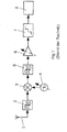
- FIG. 3 shows the inventive concept in its basic features.
- the amplifier 8 designates an analogue part which is connected to the antenna 1 on the input side and consists of two filters 9, 10, between which a variable amplifier 11 is located.
- the amplifier 11 may be a single amplifier, but may also be a cascade of amplifiers.
- the amplifier 11 is designed with the proviso that, as viewed at the output of the ADC 12, the noise level generated in a channel of the utility band by the amplifier is less than 10 dB above or below the worst case ADC generated in that channel noise level , In this way, there is a good trade-off between system sensitivity and dynamic range utilization of the ADC.
- the filters 9, 10 serve to select the frequency band coupled in via the antenna 1, the filter 10 being additionally designed to cause disturbances outside the frequency band to be received but generated by the upstream amplifier, such as harmonics or broadband noise to suppress, since these disturbances would otherwise be detected in the subsequent sampling process with the sampling frequency f S and could get into the useful signal (aliasing).
- the amplifier 11 or the cascade of attenuator and fixed amplifier is designed and controlled such that the amplitude of the analog time signal at the output of the filter 10 and at the input of the subsequent ADC 12 is controlled, so that in particular the ADC is not overridden.
- the Amplifier 11 causes a decoupling of the two filters 9, 10, so that add their attenuation values to a total attenuation.
- Denoted at 13 is a digital part connected to the ADC 12, which consists of a digital signal processing unit (DSPE) 14 and a digital-to-analog converter (DAC) 15, at the output of which the useful signal reproducible in the usual way is available.
- the DSPE 14 is set up such that the data stream 16 supplied on the input side with the word width M bits at the frequency f S is further processed, in particular demodulated, and converted on the output side into a data stream 17 having the word width N bits, which represents the useful signal implemented in the subordinate DAC 15.
- the most important element of this concept in the context of the invention is the ADC 12, since this and the sampling frequency f S and their coordination with the frequency position of the tape to be scanned, the decisive influence on the performance of the overall system.
- Fig. 2 shows a way to improve the linearity at the input of the ADC 12 by between this and the filter 10, a transformer 18 with impedance transformation (ratio of secondary to primary side of ü> 1) is arranged.
- Transformer output side, the ADC 12 is connected and in parallel a termination resistor 20.
- the voltage levels at the termination resistor 20 differ by the transmission ratio of the transformer 18 from the voltage levels at the transformer input 19, so that the transformer actually forms an amplifier in this arrangement.
- the levels at the amplifier output can be lower by the gain of the transformer than in the case without the arrangement of a transformer or when using a transformer with a 1: 1 ratio, so that through the amplifier produced distortions are lower. Distortions in a classical amplifier generally increase the further it is driven.
- transformers with the typical for the ADC input level ranges usually have a much greater linearity than amplifiers with conventional power consumption, is with the transformer arrangement according to Fig. 2 , which represents an impedance transformation, achieves an improvement in the linearity at the input of the ADC 12.
- variable amplifier 11 is used in the presentation according to Fig. 3 .
- the attenuator 22 is connected via a digital-to-analog converter (DAC) 23 to the DSPE 14, in which a digital control variable is generated, which is used after analog conversion via the DAC 23 to control the attenuation.
- DAC digital-to-analog converter
- Fig. 4 denotes a selection module, at whose output a selected from the fed antenna signal frequency band is output level-controlled.
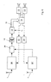
- Fig. 5 shows the application of the invention for the parallel reception of all FM and AM radio frequencies.
- the structures of both paths are basically the same, so that within the selection module between two filters a fixed amplifier with an upstream variable attenuator is arranged, in front of the inputs of the ADC 12, 12 'in each case a transformer 18, 18' for impedance transformation and linearity improvement located. Both paths are connected to a DSPE 14, which has the task of further processing the output from the two ADC 12, 12 'digital data streams.
- channel selection and demodulation paths may be implemented, which may be one or more of the digitized data AM or FM channels select, demodulate and output the resulting audio signals via the DAC 15, 15 '.
- the number of DAC modules or the demodulated channels can be almost arbitrary and is limited only by the performance of the DSPE 14.
- an FM radio band eg the European FM radio band
- an upper path which includes the selection unit 24, and fed to a combiner 25.
- the second input signal of the combiner 25 forms the selected output-side AM band of the selection module 24 '.
- This sample rate is selected so that the FM FM band is sampled in accordance with an undersampling, whereas the AM band is sampled in accordance with an oversampling. This choice of sample rate ensures that the best possible aliasing protection is achieved using common filter characteristics.
- the time signals of both paths are each separately level-controlled. Compared to the representation according to Fig. 5 Only one ADC 12 is required, however, which requires a slightly higher sampling rate, so that the hardware cost for the system can be reduced somewhat. However, this is purchased with a lower blocking resistance of the system and a slightly reduced aliasing protection. This principle is applicable even if the entire global FM radio band is to be sampled directly.
- Fig. 7 shown arrangement clarifies the basic idea of the "digital antenna", here the example of the entire FM radio band and for the band all AM services.
- the entire antenna assembly is denoted by 27, wherein the signals of one or more antennas 1, 1 'are converted by direct sampling into digital data, on the basis of the principle according to the invention, so that the - located in the signal flow direction - before the DSPE 14 assemblies are those of the Fig. 5 . 6 correspond.
- the output signals of the DSPE 14 are supplied to one or more digital data buses 26, 26 'via which the output signals of the digital antenna 27 are redistributed to one or more terminals 28, 28'.
- the digital data forwarded via the data buses 26, 26 ' can forward either parts or individual channels or subbands or even the entire bands directly scanned by the digital antenna 27 to the terminals.
- all the FM and AM radio services would be present in parallel at each of the terminals 28, 28 ', so that each terminal could demodulate or evaluate and output any number of channels in parallel by means of a plurality of tuners realized in software.
- the illustrated concept of the digital antenna 27 thus offers the highest degree of flexibility and reconfigurability since all other functions can be represented by software at the output of the digital antenna and the entire useful band is available in digital form.
- each of the terminals 28, 28 ' has access to the respective entire useful band, namely the entire AM and FM radio band, these selection paths must be adjustable by control signals from the terminals 28, 28'.
- the digital data bus 26, 26 ' is in each case configured bidirectionally and therefore may only have a smaller capacity since only parts of the output data of the digital antenna 27 are transmitted via the respective data bus. In this case, therefore, a high degree of flexibility that the digital Antenna 27 offers, exchanged against lower demands on the transmission capacity of the digital data bus.
- Fig. 8 shows the application of the invention in an antenna diversity concept with four antennas 1, 1 ', 1 ", 1"', so that a total of four input paths are found, each individually according to a single path Fig. 6 correspond.
- the diversity functionality can then be represented by software, wherein for each channel to be received from each digitally present antenna signal, this channel is selected and combined or switched according to the diversity concept.
- the tuner (s) are also represented by software.
- FIG. 8 Although illustrated example relates to a diversity system for the global FM radio band with four input antennas and two tuners represented by the DSPE 14 with correspondingly two audio outputs for demodulated signals.
- the principle is fundamentally expandable to any number of bands and any number of input antennas with a number greater than 1 and a correspondingly arbitrary number of "software tuners".
- FIG. 9 illustrates a combination of the invention with analogue tuners for the integration of further services and frequency ranges.
- the direct sampling concept can be combined with conventional mixing concepts.
- Essential for the inventive concept is an efficient and optimal utilization of the ADC dynamic range.
- the useful bands to be sampled directly here: AM and FM band
- the combiner consists of a direct merging of input and output lines.
- the sampling rate f S of the ADC is chosen such that the FM band is oversampled according to the invention (frequency position in the 2nd Nyquist zone) and the AM band is oversampled.
- the antenna 1 ", 1"' converts signal frequency bands to one or more intermediate frequencies (IF1, IF2) by means of one or more analogue tuners 29, 29'
- intermediate frequency signals are combined by means of a combiner 25 'and
- a suitable selection of the intermediate frequencies and with sufficient selection of the intermediate frequency signals it is achieved that a simultaneous digitization of the intermediate frequency signals is possible without significant aliasing interference
- the use of several identical tuners offers the possibility of antenna switching and phase diversity or the simultaneous reception of multiple channels or services on different frequencies
- the evaluation of the signals on the intermediate frequencies is performed as in direct sampling by means of several implemented on the DSPE 14 digital tuner paths, by means of which also a simultaneous evaluation of the directly sampled channels in the ADC 12 is possible.
- the ADC 12 ' can be supplied via the combiner 25' in parallel with the two tuner paths 29, 29 ', a further direct sampled FM band for the implementation of antenna or phase diversity.
- the integration of further bands to be scanned directly can also take place via one or more additional ADC or ADC channels.
- This band to the DSPE is also possible via another ADC or ADC channel.
- FIG. 10 illustrates a combination of the invention with analog tuners for the integration of further services and frequency ranges with optimized frequency domain utilization of the ADCs.
- the two intermediate frequency signals (IF1, IF2) and the output signals of the selection modules 24, 24 'to be sampled directly are now not supplied to the same ADC or ADC channel, but are split between the two ADCs 12, 12' and in each case by means of a combiner 25 ", Since the intermediate frequency signals for receiving individual channels are usually narrowband compared to the direct sampled band, a better utilization of the available ADC input frequency range is made possible Fig. 9 can the required sampling rate f S of the ADC for the arrangement after Fig. 10 be reduced.
- switches instead of combiners.
- increased aliasing protection is achieved at the expense of a loss of simultaneous receivability of the signal applied to the switch (or combiner).
- Implicitly, such a behavior can also be achieved by lowering or additionally attenuating the levels in the analogue tuners and / or the selection modules while maintaining the combiners.
- antennas 1, 1 ', 1 is always only one antenna via a switch 31 the Sparabtastungsempffiter consisting of the selection module 24, (here: set up for FM reception), the ADC 12 with the sampling frequency f s , the DACs 23rd , 15, 15 'and the DSPE 14.
- the logic for switching between the antennas is integrated in the diversity module 30. Alternatively, this logic may also be included in a digital implementation in the DSPE in which an evaluation of the digitized received signal takes place whose base is switched between the antennas.
- This concept allows receive signal optimization using antenna switching diversity for a limited frequency band or channel, which is sufficient for many applications. Compared to a direct sampling receiver with phase diversity for all receiving channels, for which the complete useful band must be scanned at least twice, the hardware complexity for this antenna switching diversity concept is significantly reduced because the useful band is scanned only once.
- This Antennenschaltdiversityun can be extended to all forms of the invention shown so far, which are therefore also subject of this invention.
Landscapes
- Engineering & Computer Science (AREA)
- Computer Networks & Wireless Communication (AREA)
- Signal Processing (AREA)
- Superheterodyne Receivers (AREA)
- Circuits Of Receivers In General (AREA)
Applications Claiming Priority (2)
| Application Number | Priority Date | Filing Date | Title |
|---|---|---|---|
| DE102007016928 | 2007-04-05 | ||
| DE102008012127A DE102008012127A1 (de) | 2007-04-05 | 2008-03-01 | Breitband-Empfangssystem |
Publications (2)
| Publication Number | Publication Date |
|---|---|
| EP1978647A2 true EP1978647A2 (fr) | 2008-10-08 |
| EP1978647A3 EP1978647A3 (fr) | 2013-10-09 |
Family
ID=39567929
Family Applications (1)
| Application Number | Title | Priority Date | Filing Date |
|---|---|---|---|
| EP08004533.9A Withdrawn EP1978647A3 (fr) | 2007-04-05 | 2008-03-12 | Système de réception à large bande |
Country Status (2)
| Country | Link |
|---|---|
| US (1) | US20080248770A1 (fr) |
| EP (1) | EP1978647A3 (fr) |
Cited By (3)
| Publication number | Priority date | Publication date | Assignee | Title |
|---|---|---|---|---|
| CN103336286A (zh) * | 2013-05-22 | 2013-10-02 | 中国电子科技集团公司第五十四研究所 | 一种基于标准pxi接口的通用宽带信号产生设备 |
| WO2016012153A1 (fr) | 2014-07-24 | 2016-01-28 | Bayerische Motoren Werke Aktiengesellschaft | Récepteur radio pour véhicule automobile, véhicule automobile, procédé et programme informatique pour récepteur radio |
| CN112865832A (zh) * | 2021-01-27 | 2021-05-28 | 中国人民解放军空军工程大学 | 地面观察哨超短波超视距信息传输设备及传输方法 |
Families Citing this family (20)
| Publication number | Priority date | Publication date | Assignee | Title |
|---|---|---|---|---|
| DE102006039357B4 (de) * | 2005-09-12 | 2018-06-28 | Heinz Lindenmeier | Antennendiversityanlage zum Funkempfang für Fahrzeuge |
| DE102007017478A1 (de) * | 2007-04-13 | 2008-10-16 | Lindenmeier, Heinz, Prof. Dr. Ing. | Empfangsanlage mit einer Schaltungsanordnung zur Unterdrückung von Umschaltstörungen bei Antennendiversity |
| EP2037593A3 (fr) * | 2007-07-10 | 2016-10-12 | Delphi Delco Electronics Europe GmbH | Installation de diversité d'antennes pour la réception radio à bande relativement large dans des véhicules |
| DE102007039914A1 (de) * | 2007-08-01 | 2009-02-05 | Lindenmeier, Heinz, Prof. Dr. Ing. | Antennendiversityanlage mit zwei Antennen für den Funkempfang in Fahrzeugen |
| DE102008003532A1 (de) * | 2007-09-06 | 2009-03-12 | Lindenmeier, Heinz, Prof. Dr. Ing. | Antenne für den Satellitenempfang |
| PT2209221T (pt) * | 2009-01-19 | 2018-12-27 | Fuba Automotive Electronics Gmbh | Sistema de recepção para a soma de sinais de antena em fase |
| DE102009011542A1 (de) * | 2009-03-03 | 2010-09-09 | Heinz Prof. Dr.-Ing. Lindenmeier | Antenne für den Empfang zirkular in einer Drehrichtung der Polarisation ausgestrahlter Satellitenfunksignale |
| DE102009023514A1 (de) * | 2009-05-30 | 2010-12-02 | Heinz Prof. Dr.-Ing. Lindenmeier | Antenne für zirkulare Polarisation mit einer leitenden Grundfläche |
| US8290020B2 (en) | 2009-06-16 | 2012-10-16 | Intel Corporation | Frequency selection method to mitigate in-band interference from inter-modulation spur of the collocated radio transmitter |
| DE102009028919A1 (de) * | 2009-08-27 | 2011-03-03 | Robert Bosch Gmbh | Verfahren und Steuergerät zur Direktabtastung einer Mehrzahl von Radiobändern |
| DE102009047388A1 (de) * | 2009-12-02 | 2011-06-09 | Robert Bosch Gmbh | Verfahren und System zum Empfang von Radiosendern |
| US20110159833A1 (en) * | 2009-12-30 | 2011-06-30 | Peter Kenington | Active antenna array for a mobile communications network with a plurality of gain switches and a method for adjusting a signal level of individual radio signals |
| JP5582039B2 (ja) * | 2011-01-07 | 2014-09-03 | 富士通株式会社 | 光伝送装置およびアナログ−デジタル変換装置 |
| EP2845321B1 (fr) * | 2012-05-03 | 2018-01-10 | Telefonaktiebolaget LM Ericsson (publ) | Appareil récepteur de radiocommunication et procédé correspondant |
| US8964898B2 (en) * | 2012-09-14 | 2015-02-24 | Northrop Grumman Systems Corporation | Multi-function receiver with switched channelizer having high dynamic range active microwave filters using carbon nanotube electronics |
| CN104798309A (zh) * | 2012-09-26 | 2015-07-22 | 爱立信(中国)通信有限公司 | 多频带接收器及其信号处理方法 |
| US9037104B2 (en) * | 2013-02-04 | 2015-05-19 | Qualcomm, Incorporated | Receiver that reconfigures between zero intermediate frequency and direct sampling based on channel conditions |
| KR102181550B1 (ko) | 2013-12-06 | 2020-11-23 | 삼성전자주식회사 | 노이즈 차단 구조를 갖는 전자 장치 |
| US9584209B2 (en) * | 2014-12-31 | 2017-02-28 | Nxp B. V. | Multiple antenna distributed radio system |
| CN116325521B (zh) * | 2020-09-29 | 2025-02-25 | 华为技术有限公司 | 一种射频接收机和无线通信装置 |
Family Cites Families (11)
| Publication number | Priority date | Publication date | Assignee | Title |
|---|---|---|---|---|
| NL9002489A (nl) * | 1990-11-15 | 1992-06-01 | Philips Nv | Ontvanger. |
| CA2066540C (fr) * | 1991-06-13 | 1998-01-20 | Edwin A. Kelley | Appareil et methode numeriques de reception de signaux a multiplexage temporel |
| US5280636A (en) * | 1991-06-13 | 1994-01-18 | Hughes Aircraft Company | Multi-band digital receiving apparatus and method with bandwidth reduction |
| EP0696854A1 (fr) * | 1994-08-08 | 1996-02-14 | THOMSON multimedia S.A. | Récepteur de radiodiffusion pour signaux analogiques et numériques |
| US6005506A (en) * | 1997-12-09 | 1999-12-21 | Qualcomm, Incorporated | Receiver with sigma-delta analog-to-digital converter for sampling a received signal |
| US6678512B1 (en) * | 2000-04-14 | 2004-01-13 | Lucent Technologies Inc. | Receiver system using analog to digital conversion at radio frequency and method |
| US6574459B1 (en) * | 2000-04-14 | 2003-06-03 | Lucent Technologies Inc. | Multiple branch receiver system and method |
| EP1193506A3 (fr) * | 2000-09-29 | 2004-07-21 | Siemens Aktiengesellschaft | Procédé pour l'échantillonnage d'un signal recu à haute fréquence, notamment d'un signal à haute fréquence d'une bobine réceptrice d'un appareil de résonance magnétique |
| US7027520B2 (en) * | 2001-08-30 | 2006-04-11 | Thomson Licensing | Method and apparatus for simultaneously retrieving portions of a data stream from different channels |
| US6882310B1 (en) * | 2003-10-15 | 2005-04-19 | Raytheon Company | Direct sampling GPS receiver for anti-interference operations |
| US7129872B1 (en) * | 2005-05-25 | 2006-10-31 | Audio Note Uk Ltd. | Audio signal analog-to-digital converter utilizing a transformed-based input circuit |
-
2008
- 2008-03-12 EP EP08004533.9A patent/EP1978647A3/fr not_active Withdrawn
- 2008-04-07 US US12/098,596 patent/US20080248770A1/en not_active Abandoned
Non-Patent Citations (1)
| Title |
|---|
| T. MÜLLER ET AL.: "Zeitschrift Frequenz", vol. 68, 2004, article "A Software Defined Multistandard Tuner Platform for Automotive Applications", pages: 136 - 139 |
Cited By (5)
| Publication number | Priority date | Publication date | Assignee | Title |
|---|---|---|---|---|
| CN103336286A (zh) * | 2013-05-22 | 2013-10-02 | 中国电子科技集团公司第五十四研究所 | 一种基于标准pxi接口的通用宽带信号产生设备 |
| WO2016012153A1 (fr) | 2014-07-24 | 2016-01-28 | Bayerische Motoren Werke Aktiengesellschaft | Récepteur radio pour véhicule automobile, véhicule automobile, procédé et programme informatique pour récepteur radio |
| DE102014214555A1 (de) | 2014-07-24 | 2016-01-28 | Bayerische Motoren Werke Aktiengesellschaft | Funkempfänger für ein Kraftfahrzeug, Kraftfahrzeug, Verfahren und Computerprogramm für einen Funkempfänger |
| CN112865832A (zh) * | 2021-01-27 | 2021-05-28 | 中国人民解放军空军工程大学 | 地面观察哨超短波超视距信息传输设备及传输方法 |
| CN112865832B (zh) * | 2021-01-27 | 2022-04-05 | 中国人民解放军空军工程大学 | 地面观察哨超短波超视距信息传输设备及传输方法 |
Also Published As
| Publication number | Publication date |
|---|---|
| US20080248770A1 (en) | 2008-10-09 |
| EP1978647A3 (fr) | 2013-10-09 |
Similar Documents
| Publication | Publication Date | Title |
|---|---|---|
| EP1978647A2 (fr) | Système de réception à large bande | |
| EP1142144B1 (fr) | Circuit pour un terminal de communication a plusieurs normes | |
| DE60133435T2 (de) | Kanalformer für ein Mehrträger Empfänger | |
| DE60032116T2 (de) | Rundfunkempfänger | |
| EP0561117A1 (fr) | Circuit pour détecter et supprimer l'interférence des canaux adjacents dans un récepteur de radiodiffusion | |
| DE19619304B4 (de) | Rundfunkempfänger | |
| DE69331653T2 (de) | Hochfrequenzschaltung für ein TDMA System | |
| EP1374397B1 (fr) | Circuit de reception pour recepteur radio mobile a reglage automatique de gain | |
| DE3828817A1 (de) | Raumdiversity-empfaengerschaltung | |
| DE102008012127A1 (de) | Breitband-Empfangssystem | |
| DE60121512T2 (de) | Sende-Empfänger und Verfahren zur Implementierung | |
| EP1748567A2 (fr) | Récepteur radio | |
| DE202007009431U1 (de) | Breitband-Empfangssystem | |
| EP0889646A2 (fr) | Récepteur de signal de télévision | |
| WO2004036781A1 (fr) | Dispositif et procede permettant de suivre un moment fixe d'echantillonnage dans des recepteurs radio | |
| EP0662267A1 (fr) | Systeme de filtrage fi pour signaux de reception fm | |
| DE10060425A1 (de) | Empfängerschaltung | |
| EP1570580B1 (fr) | Dispositif de reception pour systeme de communication sans fil | |
| WO2004110011A1 (fr) | Circuit et procede de reduction du facteur de crete | |
| EP1098454B1 (fr) | Procédé pour sélectionner une antenne parmi une pluralité d'antennes dans une installation de réception en diversité d'antennes et installation de réception en diversité d'antennes | |
| EP0597534A2 (fr) | Emetteur-récepteur radio | |
| DE19619750A1 (de) | Verstärkerschaltung mit Filter für digitale und analoge Signale | |
| EP0945998B1 (fr) | Récepteur de signaux à haute fréquence avec deux ou plus branches de réception | |
| WO2009013015A2 (fr) | Circuit de réception multistandard pour la radiodiffusion analogique et numérique | |
| DE60224987T2 (de) | Rauscharmer HF-Empfänger mit hoher Kanaltrennung |
Legal Events
| Date | Code | Title | Description |
|---|---|---|---|
| PUAI | Public reference made under article 153(3) epc to a published international application that has entered the european phase |
Free format text: ORIGINAL CODE: 0009012 |
|
| AK | Designated contracting states |
Kind code of ref document: A2 Designated state(s): AT BE BG CH CY CZ DE DK EE ES FI FR GB GR HR HU IE IS IT LI LT LU LV MC MT NL NO PL PT RO SE SI SK TR |
|
| AX | Request for extension of the european patent |
Extension state: AL BA MK RS |
|
| 17P | Request for examination filed |
Effective date: 20090423 |
|
| RIC1 | Information provided on ipc code assigned before grant |
Ipc: H04B 1/28 20060101AFI20130521BHEP Ipc: H04B 1/40 20060101ALN20130521BHEP Ipc: H04B 1/00 20060101ALI20130521BHEP |
|
| PUAL | Search report despatched |
Free format text: ORIGINAL CODE: 0009013 |
|
| AK | Designated contracting states |
Kind code of ref document: A3 Designated state(s): AT BE BG CH CY CZ DE DK EE ES FI FR GB GR HR HU IE IS IT LI LT LU LV MC MT NL NO PL PT RO SE SI SK TR |
|
| AX | Request for extension of the european patent |
Extension state: AL BA MK RS |
|
| RIC1 | Information provided on ipc code assigned before grant |
Ipc: H04B 1/28 20060101AFI20130905BHEP Ipc: H04B 1/40 20060101ALN20130905BHEP Ipc: H04B 1/00 20060101ALI20130905BHEP |
|
| AKX | Designation fees paid |
Designated state(s): DE FR IT |
|
| STAA | Information on the status of an ep patent application or granted ep patent |
Free format text: STATUS: THE APPLICATION IS DEEMED TO BE WITHDRAWN |
|
| 18D | Application deemed to be withdrawn |
Effective date: 20140410 |