EP1979072B1 - Verfahren und vorrichtung zur gewinnung von kohlendioxid aus dämpfen - Google Patents
Verfahren und vorrichtung zur gewinnung von kohlendioxid aus dämpfen Download PDFInfo
- Publication number
- EP1979072B1 EP1979072B1 EP06847190A EP06847190A EP1979072B1 EP 1979072 B1 EP1979072 B1 EP 1979072B1 EP 06847190 A EP06847190 A EP 06847190A EP 06847190 A EP06847190 A EP 06847190A EP 1979072 B1 EP1979072 B1 EP 1979072B1
- Authority
- EP
- European Patent Office
- Prior art keywords
- gas
- flue
- cooling
- carbon dioxide
- heat
- Prior art date
- Legal status (The legal status is an assumption and is not a legal conclusion. Google has not performed a legal analysis and makes no representation as to the accuracy of the status listed.)
- Not-in-force
Links
Images

Classifications
-
- B—PERFORMING OPERATIONS; TRANSPORTING
- B01—PHYSICAL OR CHEMICAL PROCESSES OR APPARATUS IN GENERAL
- B01D—SEPARATION
- B01D53/00—Separation of gases or vapours; Recovering vapours of volatile solvents from gases; Chemical or biological purification of waste gases, e.g. engine exhaust gases, smoke, fumes, flue gases, aerosols
-
- B—PERFORMING OPERATIONS; TRANSPORTING
- B01—PHYSICAL OR CHEMICAL PROCESSES OR APPARATUS IN GENERAL
- B01D—SEPARATION
- B01D53/00—Separation of gases or vapours; Recovering vapours of volatile solvents from gases; Chemical or biological purification of waste gases, e.g. engine exhaust gases, smoke, fumes, flue gases, aerosols
- B01D53/002—Separation of gases or vapours; Recovering vapours of volatile solvents from gases; Chemical or biological purification of waste gases, e.g. engine exhaust gases, smoke, fumes, flue gases, aerosols by condensation
-
- C—CHEMISTRY; METALLURGY
- C10—PETROLEUM, GAS OR COKE INDUSTRIES; TECHNICAL GASES CONTAINING CARBON MONOXIDE; FUELS; LUBRICANTS; PEAT
- C10L—FUELS NOT OTHERWISE PROVIDED FOR; NATURAL GAS; SYNTHETIC NATURAL GAS OBTAINED BY PROCESSES NOT COVERED BY SUBCLASSES C10G OR C10K; LIQUIFIED PETROLEUM GAS; USE OF ADDITIVES TO FUELS OR FIRES; FIRE-LIGHTERS
- C10L3/00—Gaseous fuels; Natural gas; Synthetic natural gas obtained by processes not covered by subclass C10G, C10K; Liquefied petroleum gas
- C10L3/06—Natural gas; Synthetic natural gas obtained by processes not covered by C10G, C10K3/02 or C10K3/04
- C10L3/10—Working-up natural gas or synthetic natural gas
-
- F—MECHANICAL ENGINEERING; LIGHTING; HEATING; WEAPONS; BLASTING
- F25—REFRIGERATION OR COOLING; COMBINED HEATING AND REFRIGERATION SYSTEMS; HEAT PUMP SYSTEMS; MANUFACTURE OR STORAGE OF ICE; LIQUEFACTION SOLIDIFICATION OF GASES
- F25J—LIQUEFACTION, SOLIDIFICATION OR SEPARATION OF GASES OR GASEOUS OR LIQUEFIED GASEOUS MIXTURES BY PRESSURE AND COLD TREATMENT OR BY BRINGING THEM INTO THE SUPERCRITICAL STATE
- F25J3/00—Processes or apparatus for separating the constituents of gaseous or liquefied gaseous mixtures involving the use of liquefaction or solidification
- F25J3/02—Processes or apparatus for separating the constituents of gaseous or liquefied gaseous mixtures involving the use of liquefaction or solidification by rectification, i.e. by continuous interchange of heat and material between a vapour stream and a liquid stream
-
- F—MECHANICAL ENGINEERING; LIGHTING; HEATING; WEAPONS; BLASTING
- F25—REFRIGERATION OR COOLING; COMBINED HEATING AND REFRIGERATION SYSTEMS; HEAT PUMP SYSTEMS; MANUFACTURE OR STORAGE OF ICE; LIQUEFACTION SOLIDIFICATION OF GASES
- F25J—LIQUEFACTION, SOLIDIFICATION OR SEPARATION OF GASES OR GASEOUS OR LIQUEFIED GASEOUS MIXTURES BY PRESSURE AND COLD TREATMENT OR BY BRINGING THEM INTO THE SUPERCRITICAL STATE
- F25J3/00—Processes or apparatus for separating the constituents of gaseous or liquefied gaseous mixtures involving the use of liquefaction or solidification
- F25J3/06—Processes or apparatus for separating the constituents of gaseous or liquefied gaseous mixtures involving the use of liquefaction or solidification by partial condensation
- F25J3/063—Processes or apparatus for separating the constituents of gaseous or liquefied gaseous mixtures involving the use of liquefaction or solidification by partial condensation characterised by the separated product stream
- F25J3/066—Processes or apparatus for separating the constituents of gaseous or liquefied gaseous mixtures involving the use of liquefaction or solidification by partial condensation characterised by the separated product stream separation of nitrogen
-
- F—MECHANICAL ENGINEERING; LIGHTING; HEATING; WEAPONS; BLASTING
- F25—REFRIGERATION OR COOLING; COMBINED HEATING AND REFRIGERATION SYSTEMS; HEAT PUMP SYSTEMS; MANUFACTURE OR STORAGE OF ICE; LIQUEFACTION SOLIDIFICATION OF GASES
- F25J—LIQUEFACTION, SOLIDIFICATION OR SEPARATION OF GASES OR GASEOUS OR LIQUEFIED GASEOUS MIXTURES BY PRESSURE AND COLD TREATMENT OR BY BRINGING THEM INTO THE SUPERCRITICAL STATE
- F25J3/00—Processes or apparatus for separating the constituents of gaseous or liquefied gaseous mixtures involving the use of liquefaction or solidification
- F25J3/06—Processes or apparatus for separating the constituents of gaseous or liquefied gaseous mixtures involving the use of liquefaction or solidification by partial condensation
- F25J3/063—Processes or apparatus for separating the constituents of gaseous or liquefied gaseous mixtures involving the use of liquefaction or solidification by partial condensation characterised by the separated product stream
- F25J3/067—Processes or apparatus for separating the constituents of gaseous or liquefied gaseous mixtures involving the use of liquefaction or solidification by partial condensation characterised by the separated product stream separation of carbon dioxide
-
- B—PERFORMING OPERATIONS; TRANSPORTING
- B01—PHYSICAL OR CHEMICAL PROCESSES OR APPARATUS IN GENERAL
- B01D—SEPARATION
- B01D2256/00—Main component in the product gas stream after treatment
- B01D2256/22—Carbon dioxide
-
- B—PERFORMING OPERATIONS; TRANSPORTING
- B01—PHYSICAL OR CHEMICAL PROCESSES OR APPARATUS IN GENERAL
- B01D—SEPARATION
- B01D2257/00—Components to be removed
- B01D2257/50—Carbon oxides
- B01D2257/504—Carbon dioxide
-
- F—MECHANICAL ENGINEERING; LIGHTING; HEATING; WEAPONS; BLASTING
- F25—REFRIGERATION OR COOLING; COMBINED HEATING AND REFRIGERATION SYSTEMS; HEAT PUMP SYSTEMS; MANUFACTURE OR STORAGE OF ICE; LIQUEFACTION SOLIDIFICATION OF GASES
- F25J—LIQUEFACTION, SOLIDIFICATION OR SEPARATION OF GASES OR GASEOUS OR LIQUEFIED GASEOUS MIXTURES BY PRESSURE AND COLD TREATMENT OR BY BRINGING THEM INTO THE SUPERCRITICAL STATE
- F25J2205/00—Processes or apparatus using other separation and/or other processing means
- F25J2205/20—Processes or apparatus using other separation and/or other processing means using solidification of components
-
- F—MECHANICAL ENGINEERING; LIGHTING; HEATING; WEAPONS; BLASTING
- F25—REFRIGERATION OR COOLING; COMBINED HEATING AND REFRIGERATION SYSTEMS; HEAT PUMP SYSTEMS; MANUFACTURE OR STORAGE OF ICE; LIQUEFACTION SOLIDIFICATION OF GASES
- F25J—LIQUEFACTION, SOLIDIFICATION OR SEPARATION OF GASES OR GASEOUS OR LIQUEFIED GASEOUS MIXTURES BY PRESSURE AND COLD TREATMENT OR BY BRINGING THEM INTO THE SUPERCRITICAL STATE
- F25J2205/00—Processes or apparatus using other separation and/or other processing means
- F25J2205/24—Processes or apparatus using other separation and/or other processing means using regenerators, cold accumulators or reversible heat exchangers
-
- F—MECHANICAL ENGINEERING; LIGHTING; HEATING; WEAPONS; BLASTING
- F25—REFRIGERATION OR COOLING; COMBINED HEATING AND REFRIGERATION SYSTEMS; HEAT PUMP SYSTEMS; MANUFACTURE OR STORAGE OF ICE; LIQUEFACTION SOLIDIFICATION OF GASES
- F25J—LIQUEFACTION, SOLIDIFICATION OR SEPARATION OF GASES OR GASEOUS OR LIQUEFIED GASEOUS MIXTURES BY PRESSURE AND COLD TREATMENT OR BY BRINGING THEM INTO THE SUPERCRITICAL STATE
- F25J2210/00—Processes characterised by the type or other details of the feed stream
- F25J2210/62—Liquefied natural gas [LNG]; Natural gas liquids [NGL]; Liquefied petroleum gas [LPG]
-
- F—MECHANICAL ENGINEERING; LIGHTING; HEATING; WEAPONS; BLASTING
- F25—REFRIGERATION OR COOLING; COMBINED HEATING AND REFRIGERATION SYSTEMS; HEAT PUMP SYSTEMS; MANUFACTURE OR STORAGE OF ICE; LIQUEFACTION SOLIDIFICATION OF GASES
- F25J—LIQUEFACTION, SOLIDIFICATION OR SEPARATION OF GASES OR GASEOUS OR LIQUEFIED GASEOUS MIXTURES BY PRESSURE AND COLD TREATMENT OR BY BRINGING THEM INTO THE SUPERCRITICAL STATE
- F25J2210/00—Processes characterised by the type or other details of the feed stream
- F25J2210/70—Flue or combustion exhaust gas
-
- F—MECHANICAL ENGINEERING; LIGHTING; HEATING; WEAPONS; BLASTING
- F25—REFRIGERATION OR COOLING; COMBINED HEATING AND REFRIGERATION SYSTEMS; HEAT PUMP SYSTEMS; MANUFACTURE OR STORAGE OF ICE; LIQUEFACTION SOLIDIFICATION OF GASES
- F25J—LIQUEFACTION, SOLIDIFICATION OR SEPARATION OF GASES OR GASEOUS OR LIQUEFIED GASEOUS MIXTURES BY PRESSURE AND COLD TREATMENT OR BY BRINGING THEM INTO THE SUPERCRITICAL STATE
- F25J2215/00—Processes characterised by the type or other details of the product stream
- F25J2215/04—Recovery of liquid products
-
- F—MECHANICAL ENGINEERING; LIGHTING; HEATING; WEAPONS; BLASTING
- F25—REFRIGERATION OR COOLING; COMBINED HEATING AND REFRIGERATION SYSTEMS; HEAT PUMP SYSTEMS; MANUFACTURE OR STORAGE OF ICE; LIQUEFACTION SOLIDIFICATION OF GASES
- F25J—LIQUEFACTION, SOLIDIFICATION OR SEPARATION OF GASES OR GASEOUS OR LIQUEFIED GASEOUS MIXTURES BY PRESSURE AND COLD TREATMENT OR BY BRINGING THEM INTO THE SUPERCRITICAL STATE
- F25J2220/00—Processes or apparatus involving steps for the removal of impurities
- F25J2220/80—Separating impurities from carbon dioxide, e.g. H2O or water-soluble contaminants
-
- F—MECHANICAL ENGINEERING; LIGHTING; HEATING; WEAPONS; BLASTING
- F25—REFRIGERATION OR COOLING; COMBINED HEATING AND REFRIGERATION SYSTEMS; HEAT PUMP SYSTEMS; MANUFACTURE OR STORAGE OF ICE; LIQUEFACTION SOLIDIFICATION OF GASES
- F25J—LIQUEFACTION, SOLIDIFICATION OR SEPARATION OF GASES OR GASEOUS OR LIQUEFIED GASEOUS MIXTURES BY PRESSURE AND COLD TREATMENT OR BY BRINGING THEM INTO THE SUPERCRITICAL STATE
- F25J2220/00—Processes or apparatus involving steps for the removal of impurities
- F25J2220/80—Separating impurities from carbon dioxide, e.g. H2O or water-soluble contaminants
- F25J2220/82—Separating low boiling, i.e. more volatile components, e.g. He, H2, CO, Air gases, CH4
-
- F—MECHANICAL ENGINEERING; LIGHTING; HEATING; WEAPONS; BLASTING
- F25—REFRIGERATION OR COOLING; COMBINED HEATING AND REFRIGERATION SYSTEMS; HEAT PUMP SYSTEMS; MANUFACTURE OR STORAGE OF ICE; LIQUEFACTION SOLIDIFICATION OF GASES
- F25J—LIQUEFACTION, SOLIDIFICATION OR SEPARATION OF GASES OR GASEOUS OR LIQUEFIED GASEOUS MIXTURES BY PRESSURE AND COLD TREATMENT OR BY BRINGING THEM INTO THE SUPERCRITICAL STATE
- F25J2220/00—Processes or apparatus involving steps for the removal of impurities
- F25J2220/80—Separating impurities from carbon dioxide, e.g. H2O or water-soluble contaminants
- F25J2220/84—Separating high boiling, i.e. less volatile components, e.g. NOx, SOx, H2S
-
- F—MECHANICAL ENGINEERING; LIGHTING; HEATING; WEAPONS; BLASTING
- F25—REFRIGERATION OR COOLING; COMBINED HEATING AND REFRIGERATION SYSTEMS; HEAT PUMP SYSTEMS; MANUFACTURE OR STORAGE OF ICE; LIQUEFACTION SOLIDIFICATION OF GASES
- F25J—LIQUEFACTION, SOLIDIFICATION OR SEPARATION OF GASES OR GASEOUS OR LIQUEFIED GASEOUS MIXTURES BY PRESSURE AND COLD TREATMENT OR BY BRINGING THEM INTO THE SUPERCRITICAL STATE
- F25J2270/00—Refrigeration techniques used
- F25J2270/02—Internal refrigeration with liquid vaporising loop
-
- F—MECHANICAL ENGINEERING; LIGHTING; HEATING; WEAPONS; BLASTING
- F25—REFRIGERATION OR COOLING; COMBINED HEATING AND REFRIGERATION SYSTEMS; HEAT PUMP SYSTEMS; MANUFACTURE OR STORAGE OF ICE; LIQUEFACTION SOLIDIFICATION OF GASES
- F25J—LIQUEFACTION, SOLIDIFICATION OR SEPARATION OF GASES OR GASEOUS OR LIQUEFIED GASEOUS MIXTURES BY PRESSURE AND COLD TREATMENT OR BY BRINGING THEM INTO THE SUPERCRITICAL STATE
- F25J2270/00—Refrigeration techniques used
- F25J2270/90—External refrigeration, e.g. conventional closed-loop mechanical refrigeration unit using Freon or NH3, unspecified external refrigeration
- F25J2270/904—External refrigeration, e.g. conventional closed-loop mechanical refrigeration unit using Freon or NH3, unspecified external refrigeration by liquid or gaseous cryogen in an open loop
-
- F—MECHANICAL ENGINEERING; LIGHTING; HEATING; WEAPONS; BLASTING
- F25—REFRIGERATION OR COOLING; COMBINED HEATING AND REFRIGERATION SYSTEMS; HEAT PUMP SYSTEMS; MANUFACTURE OR STORAGE OF ICE; LIQUEFACTION SOLIDIFICATION OF GASES
- F25J—LIQUEFACTION, SOLIDIFICATION OR SEPARATION OF GASES OR GASEOUS OR LIQUEFIED GASEOUS MIXTURES BY PRESSURE AND COLD TREATMENT OR BY BRINGING THEM INTO THE SUPERCRITICAL STATE
- F25J2290/00—Other details not covered by groups F25J2200/00 - F25J2280/00
- F25J2290/60—Details about pipelines, i.e. network, for feed or product distribution
-
- Y—GENERAL TAGGING OF NEW TECHNOLOGICAL DEVELOPMENTS; GENERAL TAGGING OF CROSS-SECTIONAL TECHNOLOGIES SPANNING OVER SEVERAL SECTIONS OF THE IPC; TECHNICAL SUBJECTS COVERED BY FORMER USPC CROSS-REFERENCE ART COLLECTIONS [XRACs] AND DIGESTS
- Y02—TECHNOLOGIES OR APPLICATIONS FOR MITIGATION OR ADAPTATION AGAINST CLIMATE CHANGE
- Y02C—CAPTURE, STORAGE, SEQUESTRATION OR DISPOSAL OF GREENHOUSE GASES [GHG]
- Y02C20/00—Capture or disposal of greenhouse gases
- Y02C20/40—Capture or disposal of greenhouse gases of CO2
Definitions
- the present invention relates to a method and a system for capturing carbon dioxide (CO 2 ) contained in fumes or other gaseous effluents from industrial installations.
- CO 2 carbon dioxide
- cryogenics or low temperature distillation
- anti-sublimation will be used in the rest of the description to denote the physical phenomenon of solid condensation in which a gas changes state to pass directly into the solid phase without liquefaction. that is, passage through the liquid state. Anti-sublimation thus constitutes the inverse physical phenomenon of sublimation, which refers to the passage of a body directly from the solid state to the gaseous state without passing through the liquid state.
- the solid carbon dioxide may subsequently be handled in solid form, for example after separation in a cyclone, or sublimated before being then liquefied downstream, or further melted directly by simple heating.
- the CO 2 content of the fumes can be quite low, for example of the order of 1 to 5%, which involves an anti-sublimation initiation temperature at atmospheric pressure which can be of the order of -110 ° C to -110 ° C.
- the present invention aims to overcome the aforementioned drawbacks and to make it possible to capture CO 2 efficiently, but at a lower cost and with simplified installations and with potentially improved efficiency.
- the portion of recovered liquid carbon dioxide, which is recycled, is thus reinjected, during the second cooling step, preferably in the form of fine solid particles, and also preferably within a heat exchanger itself.
- the method further comprises a step of pre-cooling the fumes before said first cooling step, the pre-cooling step being carried out by heat exchange with at least one of the fluids comprising the liquid water recovered during the first cooling and dehydration of the fumes, and the incondensable compounds of the fumes recovered after said second cooling step.
- the first cooling of the fumes, the dehydration of the fumes and the second cooling of the fumes operate a heat exchange with the fumes through refrigerating loops bringing frigories obtained by heat exchange with the liquefied natural gas present in a LNG terminal to be regasified.
- the first cooling of the fumes and the dehydration of the fumes operate a heat exchange with the fumes through at least one cooling loop involving glycol water.
- the second cooling of the fumes operates a heat exchange with the fumes through at least one cooling loop involving methane or nitrogen.
- the second cooling of the fumes can operate a heat exchange with the fumes through at least one additional cooling loop involving ethylene or ethane.
- the invention is applicable to all fumes from power plants and thermal installations (steelworks, cement works, etc.) using various fossil fuels (natural gas, coal, fuel, etc.) containing varying concentrations of CO 2 , even low and less than 1%.
- the dehydration of the fumes comprises a step of heat exchange with the incondensable compounds of the fumes recovered after the second cooling step.
- the fumes dehydration step is performed in a discontinuous manner with alternating a step of cooling the fumes to solidify the water on the walls of a heat exchanger and a step of heating the solidified water to allow its recovery under liquid form.
- Warming of the solidified water is effected by heat exchange with fumes before cooling during the step of cooling the fumes with solidification of the water.
- the step of second cooling of the fumes to cause an anti-sublimation of the carbon dioxide and the step of heating the solidified carbon dioxide are carried out discontinuously in alternation.
- the step of heating the solidified carbon dioxide to the triple point where a liquid phase appears can be achieved by heat exchange with flue gas before cooling during the second stage of cooling the fumes.
- the method further comprises a step of recovering the sulfur oxides contained in the fumes by anti-sublimation and reheating to the triple point where a liquid phase of the sulfur oxides appears.
- the first cooling means comprise a heat exchanger between the fumes and at least one of the fluids comprising the liquid water recovered in the first cooling means or in the means of dehydration of the fumes, and the incondensable compounds of the fumes recovered at the inlet of the second cooling means.
- the system according to the invention comprises refrigerant loops using heat transfer fluids circulating on the one hand in heat exchangers present in a methane terminal to ensure a heat exchange with liquefied natural gas subjected to a process of regasification and secondly in heat exchangers arranged in at least one of the first cooling means, dehydration means and second cooling means to ensure heat exchange with the fumes giving rise to the capture of the dioxide of carbon.
- the system comprises at least one refrigeration loop using as heat transfer fluid water glycoled and including at least one heat exchanger disposed in the first cooling means or the dehydration means.
- the system comprises at least one refrigeration loop using as heat transfer fluid methane or nitrogen and including at least one heat exchanger disposed in the second cooling means.
- the system may further comprise a refrigerant loop using as heat transfer fluid ethylene or ethane; and including at least one heat exchanger disposed in the second cooling means.
- the system may comprise means for recovering incondensable smoke compounds at the outlet of the second cooling means and means for heat exchange with at least the means for dehydrating the flue gases.
- the means for dehydrating the flue gases comprise at least first and second enclosures provided with heat exchangers and capable of receiving fumes in a discontinuous manner so as to ensure in each case a cooling of the fumes with solidification in turn. the water contained in the fumes on the walls of the enclosure concerned and a warming of the solidified water to allow recovery of the water in liquid form.
- the second smoke cooling means and said heating means comprise at least first and second enclosures equipped with heat exchangers and able to receive smoke in a discontinuous manner so as to ensure each in turn, a cooling of the fumes with anti-sublimation of the carbon dioxide which is deposited on the walls of the enclosure concerned, and a warming of the carbon dioxide solidified to cause the melting thereof.
- the system may further comprise means for recovering sulfur oxides in the heating means in a closed chamber.
- this phenomenon is applicable to all fumes from power stations and thermal installations using various fossil fuels (natural gas, coal, fuel, etc.) containing varying concentrations of CO 2 from 1% to concentrations of several tens of percent.
- Table 1 gives as an example the typical composition of the fumes of a gas turbine.
- Table 1- Composition of gas turbine fumes N 2 H 2 O O 2 CO 2 Moist base composition (%) 76 6 14 4 Dry base molar composition (%) 81 - 15 4
- the fumes after removal of the water, contain about 4% CO 2 (partial pressure of 0.04 bar).
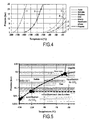
- the solid CO 2 entrapped in the exchanger can then be reheated and evolve to the conditions of the triple point of CO 2 where the liquid CO 2 can be removed in order to shift the thermodynamic equilibrium in favor of the production of liquid CO 2 ( see the dotted upper curve on the Figure 5 ).
- the start temperature of the anti-sublimation process depends on the CO 2 content of the fumes. Thus, it varies from -78.5 ° C for pure CO 2 at atmospheric pressure to -121.9 ° C for an effluent containing a partial pressure of 0.01 bar CO 2 (see Table 2).
- Table 2 Starting temperature of the CO 2 anti-sublimation process as a function of the CO 2 contents of the fumes at atmospheric pressure CO 2 content 100 15 10 5 2 1 0.1
- a fraction of the liquid CO 2 obtained at the process outlet is recycled by expansion until solid particles are formed in the last exchanger so as to create nucleation centers.
- This recycling makes it possible to optimize the anti-sublimation exchanger in terms of the exchange surface and the final operating temperature.
- the Figure 1 shows an advantageous example of implementation of the invention in the context of the capture of fumes produced by an industrial installation 10.
- the combustion fumes are available at a temperature of the order of 40 ° C at the inlet of the CO 2 treatment and capture plant 110.
- the industrial plant 10 is located nearby (for example at a distance of the order of a few hundred meters to a few kilometers) of a LNG terminal 200 which receives liquefied natural gas (LNG) for example at - 161 ° C under a pressure of 80 bar, on a line 201.
- the LNG passes through a heat exchanger 203 which operates a heat exchange between the LNG and heat transfer fluids circulating in exchangers 204, 205 of refrigerant loops 210, 220.
- the natural gas continues the regasification process.
- This regasified natural gas may, for example, be used to supply the industrial plant 10, such as a thermal power station, with a line 206.
- the invention applies to the capture of CO 2 in combustion fumes, but can also be applied to the capture of CO 2 in other gaseous effluents such as synthesis gases obtained in the context of the production of CO 2. 'hydrogen.
- the invention also makes it possible to carry out, by the same anti-sublimation process, the capture of sulfur oxides (SO x ) that may be present in the fumes beside the CO 2 .
- the fumes serve as a hot source for the refrigerated loops 210, 220 while the LNG at - 161 ° C ensures the supply of frigories.
- the cooling of the fumes provided on the line 101 takes place in several stages.
- a cooling device 120 comprising an exchanger 122 of a refrigerating loop 210, for example with brine
- the combustion fumes are cooled from 40 ° C to 1 ° C to cause in the chamber 121 the liquid condensation (liquefaction) a 123 fraction of the water present in the fumes.
- the condensed water 123 is discharged through a pipe 124 and can be for example returned to a heat exchanger 111 which can operate a pre-cooling of the fumes before entering the cooling device 120.
- the water heated in the heat exchanger 111 makes it possible to reduce the temperature of the fumes, for example to 30 ° C., and is evacuated via a line 113 to a close temperature ambient temperature (30 ° C).
- the fumes from the cooling device 120 are introduced via a line 125 into a device 130 for dehydrating the fumes.
- the dehydration of the fumes is necessary to eliminate the residual water (approximately 0.6% of water in the fumes, if we consider that the vapor pressure of the water at 1 ° C is 6.6 mbar) .
- the residual water can solidify and subsequently block the installation and end up in the captured CO 2 .
- the dehydration operation can also be carried out using LNG frigories of the LNG terminal 200, for example by means of a heat exchanger 133 that can be inserted, if necessary, in the same refrigerating loop 210 (for example with water). glycolée) than the exchanger 122.
- the residual water can thus be solidified for example at -30 ° C., on the walls of one (131) of the at least two enclosures 131, 132 operating discontinuously alternately ("in batch").
- the fumes When water is solidified on the walls of an enclosure 131, the fumes are tipped towards the inlet of the other or one of the other enclosures 132 to similarly cause the solidification of the residual water . During this time, the solidified water on the walls of the first chamber 131 is heated, for example by using the heat of the fumes by passing through the first chamber 131 before entering a second chamber 132, where it must then occur. 'water.
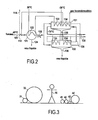
- this shows the fumes saturated with water at 1 ° C arriving on the line 125 to first enter the chamber 132 (whose exchangers 133, 134 are deactivated) in order to cause the melting of the solidified water on the walls of the enclosure, and the evacuation of the liquid water by a pipe 136.
- the fumes are then conducted through the channel 126 to the capture chamber 131 in which the exchangers 133, 134 are activated to cool the fumes and capture the residual water that solidifies on the walls of the enclosure 131.
- the fumes then exit through a pipe 135 to be conducted to the CO 2 capture stage.
- the fumes arriving via line 125 are tilted over the dotted path on the Figure 2 to first enter the enclosure 131 to cause the melting of the water and its evacuation through the pipe 136, then the fumes are introduced into the chamber 132 in which the heat exchangers 133, 134 are then activated, to cause the solidification of the residual water.
- the fumes leaving enclosure 132 are then transferred via line 135 to the next CO 2 capture stage.
- a heat exchanger 134 such as that previously described, which is part of a heat exchange refrigeration loop for example with the LNG of a methane terminal. It is also possible to use a heat exchanger 134 in which incondensable gases (nitrogen, oxygen, etc.) recovered in the fumes at the outlet 145 of the CO 2 capture process flow.
- the incondensable gases can also subsequently be transferred to a heat exchanger 112 providing, like the heat exchanger 111, pre-cooling and removal of the condensed water in a stage 110 located upstream of the cooling device 120 and dehydration 130. Residual incondensable gases (O 2 , N 2 , ...) can then be released into the atmosphere via a line 114 at a temperature of the order of 30 ° C ( Figures 1 and 2 ).
- the liquid water discharged through the pipes 136 may, like the water recovered via the pipe 124, be used to ensure pre-cooling in the exchanger 111.
- the fumes present in the pipe 135 at the outlet of the dehydration stage 130 may have a temperature of the order of -30 ° C. and are introduced into another cooling device 140 which may comprise one or more heat exchangers 143 making part of refrigerating loops such as the loop 220 bringing frigories from the LNG present in the LNG terminal 200.
- the cooling device 140 comprises at least two enclosures 141, 142 each comprising a heat exchanger 143 forming part of the refrigerating loop 220 and means 144, 155 for withdrawing or pumping liquid and / or gaseous CO 2 and, where appropriate also sulfur dioxide.
- the loudspeakers 141, 142 operate alternately alternately in turn (“batch" operation) to capture the CO 2 (respectively SO 2 ) by anti-sublimation and then cause the latter to melt.
- the operation is similar to what has been explained with reference to the Figure 2 for catching water.
- the flue gases are swung towards the enclosure 142.
- the The heat exchanger 143 is deactivated and the flue gas energy can be used to raise the temperature of the solid CO 2 which heats up to a temperature of, for example, -130 ° C to a temperature of about -56.6 ° C. with a partial pressure of CO 2 of 5.18 bar, which corresponds to the triple point where the liquid and gaseous phases appear and coexist simultaneously (see Figure 5 ).
- an important feature of the invention lies in the fact that a fraction of the liquid CO 2 obtained on the line 144 at the outlet of the cooling device 140 and recovered in the tank 150 is recycled by a pipe 152 provided with a valve 153 or (dashed lines) towards the supply pipe 135 dehydrated fumes at the inlet of the cooling device 140, preferably preferably (continuous lines) directly into the enclosures 141, 142 in order to create nucleation centers for the anti-sublimation of CO 2 .
- the Figure 4 gives the gas / liquid balance curves between -200 and -30 ° C of some compounds that can be used as heat transfer fluids in the refrigerating loops 210, 220. These compounds are nitrogen, methane, ethylene, CO 2 ; ethane, hexafluoroethane, propane (curves referenced 1 to 7 respectively).
- the power refrigerant required for the capture of 320 t CO 2 per hour is 192 MW.
- the nitrogen flow rate to be transported is more than one million Nm 3 / h, ie a pipe diameter.
- the dehydration of the fumes is carried out by cooling the fumes from 40 ° C to 1 ° C with removal of the free water, and then at sufficiently low temperatures to reach the desired water contents.
- the dehydration operation is performed using a brine loop 210 which, depending on the glycol content (ethylene glycol, propylene glycol), can achieve -40 ° C .
- Table 3 gives the water content of the fumes and CO 2 captured as a function of the cooling temperature.
- Table 3 Water content of fumes and CO 2 captured as a function of cooling temperature and for a 100% capture rate Fume cooling temperature (° C) Flue gas content (ppm) Water content of captured CO 2 (ppm) - 30 490 1.3% - 40 180 0.5% - 50 60 1650 - 60 18 490 - 70 5 130 - 80 1 30 - 90 0.1 5
- the water content of the fumes is thus 490 ppm, ie about 5g of water / kg of CO 2 captured (1.3%).
- the fumes can be cooled to about -75 ° C with the use of an additional refrigerant loop on the dehydration part of the fumes.
- This additional cooling loop could be a loop using LNG frigories and a heat transfer fluid such as methane or ethylene.
- this additional loop is preferably, as shown in FIG. Figure 1 a loop using the incondensable gases available at the outlet 145 of the anti-sublimation stage, to continue in the exchanger 134 the cooling of the fumes and to obtain a temperature of the order of -75 ° C at the exit 135 of the dehydration device.
- Table 4 gives figures for an example of a flue gas dehydration plant in a 800 MW natural gas combined cycle, with a cooling capacity of 164 MW to achieve dewatering, distributed between exchanger 122 (99 MW) and the exchanger 133 (65 MW).
- the flow rate of water to be transported is about 2500 m 3 / h is a diameter of l order of 0.30 m for the pipes 41 and 42 of the Figure 3 .
- the cooling capacity required for the cooling of fumes from -75 ° C to -90 ° C and the anti-sublimation of CO 2 is 50 MW (of which 21 MW for the cooling of fumes from -75 ° C to -90 ° C and 29 MW for the anti-sublimation of CO 2 ).
- the pipe diameter will be 0.20 m for the liquid side pipe 43 if the liquid velocity is 10 m / s (or 0.30 m if the liquid velocity is 3 m / s) and 0.80 m for the gas side 44 (10 m / s) ( Figure 3 ).
Landscapes
- Engineering & Computer Science (AREA)
- Chemical & Material Sciences (AREA)
- Chemical Kinetics & Catalysis (AREA)
- Oil, Petroleum & Natural Gas (AREA)
- Physics & Mathematics (AREA)
- Mechanical Engineering (AREA)
- Thermal Sciences (AREA)
- General Engineering & Computer Science (AREA)
- General Chemical & Material Sciences (AREA)
- Analytical Chemistry (AREA)
- Organic Chemistry (AREA)
- Treating Waste Gases (AREA)
- Carbon And Carbon Compounds (AREA)
- Gas Separation By Absorption (AREA)
- Vaporization, Distillation, Condensation, Sublimation, And Cold Traps (AREA)
- Separation By Low-Temperature Treatments (AREA)
- Surgical Instruments (AREA)
- Joining Of Building Structures In Genera (AREA)
- Joints Allowing Movement (AREA)
- Organic Low-Molecular-Weight Compounds And Preparation Thereof (AREA)
Claims (25)
- Verfahren zur Rückgewinnung von Kohlendioxid, das in Dämpfen vorhanden ist, umfassend die folgenden Schritte:a) erstes Abkühlen der Dämpfe, um durch Kondensieren eine Fraktion des Wassers zu entfernen, das in den Dämpfen vorhanden ist,b) Dehydratisieren der Dämpfe, um das Restwasser zu entfernen,c) zweites Abkühlen der Dämpfe durch Wärmeaustausch, um die Dämpfe auf eine Temperatur zu bringen, bei der das Kohlendioxid durch Desublimieren direkt vom gasförmigen Zustand in den festen Zustand übergeht,d) nach Ableiten der Dämpfe, Wiederaufheizen des verfestigten Kohlendioxids in einem geschlossenen Behälter bis zum Tripelpunkt, an dem sich eine flüssige Phase ausbildet, unde) Abziehen oder Abpumpen des flüssigen und/oder gasförmigen Kohlendioxids in einen thermisch isolierten Tank,dadurch gekennzeichnet, daß ein Teil des rückgewonnenen flüssigen Kohlendioxids recycelt wird und, nach Entspannung bis auf Atmosphärendruck, während des Schritts des zweiten Abkühlens auf kontinuierliche oder diskontinuierliche Weise erneut injiziert wird, um mit den Dämpfen gemischt zu werden, die zuvor aus dem Schritt des Dehydratisierens hervorgegangen sind.
- Verfahren nach Anspruch 1, dadurch gekennzeichnet, daß der Teil des rückgewonnenen flüssigen Kohlendioxids, das recycelt wurde, während des Schritts des zweiten Abkühlens in Form von feinen Feststoffpartikeln erneut injiziert wird.
- Verfahren nach Anspruch 1 oder Anspruch 2, dadurch gekennzeichnet, daß der Teil des rückgewonnenen flüssigen Kohlendioxids, das recycelt wurde, während des Schritts des zweiten Abkühlens direkt im Innern eines Wärmetauschers erneut injiziert wird.
- Verfahren nach irgendeinem der Ansprüche 1 bis 3, dadurch gekennzeichnet, daß es ferner einen Schritt des Vorabkühlens der Dämpfe vor dem Schritt des ersten Abkühlens umfaßt, wobei der Schritt des Vorabkühlens durch Wärmeaustausch mit mindestens einem der Fluide erfolgt, die das flüssige Wasser, das während der Schritte des ersten Abkühlens und des Dehydratisierens der Dämpfe rückgewonnen wurde, und die nicht kondensierbaren Verbindungen der Dämpfe umfassen, die nach dem Schritt des zweiten Abkühlens rückgewonnenen wurden.
- Verfahren nach irgendeinem der Ansprüche 1 bis 4, dadurch gekennzeichnet, daß das erste Abkühlen der Dämpfe, das Dehydratisieren der Dämpfe und das zweite Abkühlen der Dämpfe einen Wärmeaustausch mit den Dämpfen über Kühlkreisläufe herbeiführen, die Kilokalorien mit sich führen, die durch Wärmeaustausch mit dem verflüssigten Erdgas erhalten wurden, das in einem Flüssiggasterminal vorhanden ist, um regasifiziert zu werden.
- Verfahren nach Anspruch 5, dadurch gekennzeichnet, daß das erste Abkühlen der Dämpfe und das Dehydratisieren der Dämpfe einen Wärmeaustausch mit den Dämpfen über mindestens einen Kühlkreislauf herbeiführen, wobei ein glykolhaltiges Wasser eingesetzt wird.
- Verfahren nach Anspruch 5 oder Anspruch 6, dadurch gekennzeichnet, daß das zweite Abkühlen der Dämpfe einen Wärmeaustausch mit den Dämpfen über mindestens einen Kühlkreislauf herbeiführt, wobei Methan oder Stickstoff eingesetzt wird.
- Verfahren nach Anspruch 7, dadurch gekennzeichnet, daß das zweite Abkühlen der Dämpfe einen Wärmeaustausch mit den Dämpfen über mindestens einen zusätzlichen Kühlkreislauf herbeiführt, wobei Ethylen oder Ethan eingesetzt wird.
- Verfahren nach irgendeinem der Ansprüche 1 bis 8, dadurch gekennzeichnet, daß das Dehydratisieren der Dämpfe einen Schritt des Wärmeaustauschens mit den nicht kondensierbaren Verbindungen der Dämpfe umfaßt, die nach dem Schritt des zweiten Abkühlens rückgewonnen wurden.
- Verfahren nach irgendeinem der Ansprüche 1 bis 9, dadurch gekennzeichnet, daß der Schritt des Dehydratisierens der Dämpfe auf diskontinuierliche Weise abwechselnd mit einem Schritt des Abkühlens der Dämpfe, um das Wasser an den Wänden eines Wärmeaustauschers zu verfestigen, und einem Schritt des Aufheizens des verfestigten Wassers, um seine Rückgewinnung in flüssiger Form zu ermöglichen, durchgeführt wird.
- Verfahren nach Anspruch 10, dadurch gekennzeichnet, daß das Aufheizen des verfestigten Wassers durch Wärmeaustausch mit Dämpfen vor deren Abkühlung während des Schritts des Abkühlens der Dämpfe mit Verfestigung des Wassers durchgeführt wird.
- Verfahren nach irgendeinem der Ansprüche 1 bis 11, dadurch gekennzeichnet, daß der Schritt des zweiten Abkühlens der Dämpfe, um ein Desublimieren des Kohlendioxids zu bewirken, und der Schritt des Aufheizens des verfestigten Kohlendioxids abwechselnd auf diskontinuierliche Weise ausgeführt werden.
- Verfahren nach Anspruch 12, dadurch gekennzeichnet, daß der Schritt des Aufheizens des verfestigten Kohlendioxids bis zum Tripelpunkt, an dem sich eine flüssige Phase ausbildet, durch Wärmeaustausch mit Dämpfen vor deren Abkühlen während des Schritts des zweiten Abkühlens der Dämpfe ausgeführt wird.
- Verfahren nach irgendeinem der Ansprüche 1 bis 13, dadurch gekennzeichnet, daß es ferner einen Schritt der Rückgewinnung der Schwefeloxide, die in den Dämpfen enthalten sind, durch Desublimieren und Aufheizen bis zum Tripelpunkt, an dem sich eine flüssige Phase der Schwefeloxide ausbildet, umfaßt.
- System zur Rückgewinnung von Kohlendioxid, das in Dämpfen vorhanden ist, umfassend:a) erste Mittel (110, 120) zum Abkühlen der Dämpfe, die mindestens einen Wärmetauscher (122) umfassen, um durch Kondensieren eine Fraktion von Wassers zu entfernen, das in den Dämpfen vorhanden ist,b) Mittel (130) zum Dehydratisieren der Dämpfe,c) zweite Mittel (140) zum Abkühlen der Dämpfe, die mindestens einen Wärmeaustauscher (143) umfassen, um die Dämpfe auf eine Temperatur zu bringen, die ein Desublimieren des Kohlendioxids, das in den Dämpfen vorhanden ist, bewirkt,d) Mittel (141, 142) zum Aufheizen des verfestigten Kohlendioxids in einem geschlossenen Behälter, um dessen Verflüssigung zu bewirken,e) Mittel (144) zum Abziehen oder Abpumpen des flüssigen und/oder gasförmigen Kohlendioxids in einen wärmeisolierten Tank (150),dadurch gekennzeichnet, daß es ferner Mittel (152, 153) zur Entspannung bis auf Atmosphärendruck eines Teils des rückgewonnenen flüssigen Kohlendioxids und zur erneuten Injektion dieses Teils des Kohlendioxids in die Dämpfe in den zweiten Mittel (140) zum Abkühlen der Dämpfe umfaßt.
- System nach Anspruch 15, dadurch gekennzeichnet, daß es Mittel zum erneuten Injizieren des Teil des rückgewonnenen flüssigen Kohlendioxids in Form von feinen Feststoffpartikeln in die Dämpfe umfaßt.
- System nach Anspruch 15 oder Anspruch 16, dadurch gekennzeichnet, daß die ersten Mittel zum Abkühlen einen Wärmeaustauscher (111, 112) zwischen den Dämpfen und mindestens einem der Fluide, die das rückgewonnene flüssige Wasser in den ersten Mitteln (120) zum Abkühlen oder in den Mitteln (130) zur Dehydratisieren der Dämpfe umfassen, und den nicht kondensierbaren Verbindungen der Dämpfe, die am Einlaß der zweiten Mittel zum Abkühlen (144) rückgewonnen wurden, umfassen.
- System nach irgendeinem der Ansprüche 15 bis 17, dadurch gekennzeichnet, daß es Kühlkreisläufe (210, 220) umfaßt, die Wärmeübertragungsfluide verwenden, die einerseits in den Wärmeaustauschern (204, 205), die in einem Flüssiggasterminal vorhanden sind, um einen Wärmeaustausch mit dem verflüssigten Erdgas zu gewährleisten, das einem Regasifizierungsvorgang unterzogen wird, und andererseits in den Wärmeaustauschern (122, 133, 143) zirkulieren, die in mindestens einem der ersten Mittel (120) zum Abkühlen, der Mittel (130) zum Dehydratisieren und der zweiten Mittel (140) zum Abkühlen angeordnet sind, um einen Wärmeaustausch mit den Dämpfen zu gewährleisten, der zur Gewinnung des Kohlendioxids führt.
- System nach Anspruch 18, dadurch gekennzeichnet, daß es mindestens einen Kühlkreislauf (210) umfaßt, der als Wärmeübertragungsfluid ein glykolhaltiges Wasser verwendet und mindestens einen Wärmeaustauscher (122, 133) enthält, der in den ersten Mitteln (120) zum Abkühlen oder den Mitteln (130) zum Dehydratisieren angeordnet ist.
- System nach Anspruch 18 oder Anspruch 19, dadurch gekennzeichnet, daß es mindestens einen Kühlkreislauf (220) umfaßt, der als Wärmeübertragungsfluid Methan oder Stickstoff verwendet und mindestens einen Wärmeaustauscher enthält, der in den zweiten Mitteln (140) zum Abkühlen angeordnet ist.
- System nach Anspruch 20, dadurch gekennzeichnet, daß es ferner mindestens einen Kühlkreislauf umfaßt, der als Wärmeübertragungsfluid Ethylen oder Ethan verwendet und mindestens einen Wärmeaustauscher enthält, der in den zweiten Mitteln (140) zum Abkühlen angeordnet ist.
- System nach irgendeinem der Ansprüche 15 bis 21, dadurch gekennzeichnet, daß es Mittel (145) zur Rückgewinnung der nicht kondensierbaren Verbindungen der Dämpfe am Auslaß der zweiten Mittel (140) zum Abkühlen und Mittel (134) zum Wärmeaustausch mit mindestens den Mitteln (130) zum Dehydratisieren der Dämpfe umfaßt.
- System nach irgendeinem der Ansprüche 15 bis 22, dadurch gekennzeichnet, daß die Mittel (130) zum Dehydratisieren der Dämpfe mindestens erste und zweite Behälter (131, 132) umfassen, die mit Wärmeaustauschern (133, 134) ausgestattet sind und die Dämpfe auf diskontinuierliche Weise aufnehmen können, um jeweils abwechselnd ein Abkühlen der Dämpfe mit Verfestigung des in den Dämpfen enthaltenen Wassers an den Wänden des betrachteten Behälters und ein Aufheizen des verfestigten Wassers zu gewährleisten, um eine Rückgewinnung des Wassers in flüssiger Form zu ermöglichen.
- System nach irgendeinem der Ansprüche 15 bis 23, dadurch gekennzeichnet, daß die zweiten Mittel (140) zum Abkühlen der Dämpfe und die Mittel zum Aufheizen mindestens erste und zweite Behälter (141, 142) umfassen, die mit Wärmeaustauschern (143) ausgestattet sind und die Dämpfe auf diskontinuierliche Weise aufnehmen können, um jeweils abwechselnd ein Abkühlen der Dämpfe mit Desublimieren des Kohlendioxids, das an den Wänden des betrachteten Behälters abgeschieden ist, und ein Aufheizen des verfestigten Kohlendioxids zu gewährleisten, um dessen Fusion zu bewirken.
- System nach irgendeinem der Ansprüche 15 bis 24, dadurch gekennzeichnet, daß es ferner Mittel (155) zur Rückgewinnung von Schwefeloxiden in den Mitteln (141, 142) zum Aufheizen in einem geschlossenen Behälter umfaßt.
Priority Applications (1)
| Application Number | Priority Date | Filing Date | Title |
|---|---|---|---|
| PL06847190T PL1979072T3 (pl) | 2005-12-21 | 2006-12-20 | Sposób i instalacja do wychwytywania dwutlenku węgla znajdującego się w dymach |
Applications Claiming Priority (2)
| Application Number | Priority Date | Filing Date | Title |
|---|---|---|---|
| FR0513078A FR2894838B1 (fr) | 2005-12-21 | 2005-12-21 | Procede et systeme de capture du dioxyde de carbone present dans des fumees |
| PCT/FR2006/051400 WO2007074294A2 (fr) | 2005-12-21 | 2006-12-20 | Procede et systeme de capture de dioxyde de carbone present dans des fumees |
Publications (2)
| Publication Number | Publication Date |
|---|---|
| EP1979072A2 EP1979072A2 (de) | 2008-10-15 |
| EP1979072B1 true EP1979072B1 (de) | 2010-05-05 |
Family
ID=36974704
Family Applications (1)
| Application Number | Title | Priority Date | Filing Date |
|---|---|---|---|
| EP06847190A Not-in-force EP1979072B1 (de) | 2005-12-21 | 2006-12-20 | Verfahren und vorrichtung zur gewinnung von kohlendioxid aus dämpfen |
Country Status (11)
| Country | Link |
|---|---|
| US (1) | US20080302133A1 (de) |
| EP (1) | EP1979072B1 (de) |
| JP (1) | JP4971356B2 (de) |
| KR (1) | KR20080085148A (de) |
| AT (1) | ATE466637T1 (de) |
| DE (2) | DE602006014211D1 (de) |
| ES (1) | ES2345278T3 (de) |
| FR (1) | FR2894838B1 (de) |
| PL (1) | PL1979072T3 (de) |
| PT (1) | PT1979072E (de) |
| WO (1) | WO2007074294A2 (de) |
Families Citing this family (61)
| Publication number | Priority date | Publication date | Assignee | Title |
|---|---|---|---|---|
| JP4721349B2 (ja) * | 2006-03-10 | 2011-07-13 | 国立大学法人 筑波大学 | バイオガス中のメタン濃度の安定化システム及びバイオガス中のメタン濃度の安定化方法 |
| US20110226010A1 (en) * | 2007-11-28 | 2011-09-22 | Brigham Young University | Carbon dioxide capture from flue gas |
| EP2085587A1 (de) | 2008-02-04 | 2009-08-05 | ALSTOM Technology Ltd | Kombinierte Zyklusstromanlage mit niedriger Kohlenstoffemission und Verfahren dafür |
| WO2009117763A1 (en) * | 2008-03-27 | 2009-10-01 | Bioseq Pty Ltd | Capture of carbon dioxide from flue gases in large-scale algae cultivation |
| US20090288447A1 (en) * | 2008-05-22 | 2009-11-26 | Alstom Technology Ltd | Operation of a frosting vessel of an anti-sublimation system |
| US20090301108A1 (en) * | 2008-06-05 | 2009-12-10 | Alstom Technology Ltd | Multi-refrigerant cooling system with provisions for adjustment of refrigerant composition |
| US8163070B2 (en) * | 2008-08-01 | 2012-04-24 | Wolfgang Georg Hees | Method and system for extracting carbon dioxide by anti-sublimation at raised pressure |
| US20100050687A1 (en) * | 2008-09-04 | 2010-03-04 | Alstom Technology Ltd | Liquefaction of gaseous carbon-dioxide remainders during anti-sublimation process |
| FR2940414B1 (fr) * | 2008-12-19 | 2012-10-26 | Air Liquide | Procede de capture du dioxyde de carbone par cryo-condensation |
| FR2940413B1 (fr) * | 2008-12-19 | 2013-01-11 | Air Liquide | Procede de capture du co2 par cryo-condensation |
| WO2010107820A2 (en) * | 2009-03-16 | 2010-09-23 | Brigham Young University | Methods and systems for separating condensable vapors from gases |
| FR2944096B1 (fr) | 2009-04-07 | 2012-04-27 | Ass Pour La Rech Et Le Dev De Methodes Et Processus Indutriels Armines | Procede et systeme frigorifique pour la recuperation de la froideur du methane par des fluides frigorigenes. |
| FR2949072B1 (fr) * | 2009-08-13 | 2017-03-31 | Ass Pour La Rech Et Le Dev Des Methodes Et Processus Industriels-Armines | Procede et systeme ameliores pour l'extraction d'une substance par antisublimation et fusion |
| KR101149510B1 (ko) * | 2009-10-14 | 2012-05-25 | 삼성중공업 주식회사 | Lng 재기화 설비를 이용한 이산화탄소 분리 액화 장치 및 방법 |
| KR101027809B1 (ko) * | 2010-02-12 | 2011-04-07 | 한솔이엠이(주) | 액화바이오메탄 제조장치 |
| CA2802231A1 (en) | 2010-07-02 | 2012-01-05 | Union Engineering A/S | High pressure recovery of carbon dioxide from a fermentation process |
| AU2012258510B2 (en) * | 2011-05-26 | 2016-09-22 | Sustainable Energy Solutions, Llc | Systems and methods for separating condensable vapors from light gases or liquids by recuperative cryogenic processes |
| WO2012174418A1 (en) | 2011-06-15 | 2012-12-20 | L'air Liquide Societe Anonyme Pour L'etude Et L'exploitation Des Procedes Georges Claude | Process for removing carbon dioxide from a gas stream using desublimation |
| US20130084794A1 (en) * | 2011-09-29 | 2013-04-04 | Vitali Victor Lissianski | Systems and methods for providing utilities and carbon dioxide |
| US9410736B2 (en) * | 2011-10-22 | 2016-08-09 | Sustainable Energy Solutions, Llc | Systems and methods for integrated energy storage and cryogenic carbon capture |
| ES2574263T3 (es) * | 2011-11-02 | 2016-06-16 | 8 Rivers Capital, Llc | Sistema de generación de energía y procedimiento correspondiente |
| US9068463B2 (en) | 2011-11-23 | 2015-06-30 | General Electric Company | System and method of monitoring turbine engines |
| WO2014011903A1 (en) * | 2012-07-11 | 2014-01-16 | Fluor Technologies Corporation | Configurations and methods of co2 capture from flue gas by cryogenic desublimation |
| US20140144178A1 (en) * | 2012-11-28 | 2014-05-29 | L'Air Liquide Societe Anonyme Pour L'Etude Et L'Expoitation Des Procedes Georges Claude | Optimized heat exchange in a co2 de-sublimation process |
| FR3004964A1 (fr) * | 2013-04-30 | 2014-10-31 | Salah Hassanin | Systeme de purification des fumees emanant des usines par refroidissement et intensification. |
| CA2912435A1 (en) * | 2013-05-13 | 2014-11-20 | Refrigeration Engineering International Pty Limited | Apparatus and process to condition natural gas for transportation |
| US10473029B2 (en) | 2013-12-30 | 2019-11-12 | William M. Conlon | Liquid air power and storage |
| WO2016195968A1 (en) | 2015-06-01 | 2016-12-08 | Conlon William M | Part load operation of liquid air power and storage system |
| WO2016195999A1 (en) | 2015-06-03 | 2016-12-08 | Conlon William M | Liquid air power and storage with carbon capture |
| WO2016204893A1 (en) | 2015-06-16 | 2016-12-22 | Conlon William M | Cryogenic liquid energy storage |
| WO2017069922A1 (en) | 2015-10-21 | 2017-04-27 | Conlon William M | High pressure liquid air power and storage |
| CN105600783A (zh) * | 2015-12-27 | 2016-05-25 | 安徽淮化股份有限公司 | 一种食品级液体co2储罐放空气冷量回收利用的装置及方法 |
| WO2018222230A1 (en) | 2017-02-24 | 2018-12-06 | Exxonmobil Upstream Research Company | Method of purging a dual purpose lng/lin storage tank |
| KR102029193B1 (ko) * | 2017-10-30 | 2019-11-08 | 두산중공업 주식회사 | 액화 천연 가스의 냉열을 이용한 이산화탄소 포집 장치 및 발전 시스템 |
| CN109813054B (zh) * | 2017-11-22 | 2021-03-30 | 斗山重工业建设有限公司 | 利用液化天然气的冷能的二氧化碳捕集装置及发电系统 |
| US12030000B2 (en) * | 2017-12-22 | 2024-07-09 | Sustainable Energy Solutions, Llc | Vessel and method for solid-liquid separation |
| US11536510B2 (en) | 2018-06-07 | 2022-12-27 | Exxonmobil Upstream Research Company | Pretreatment and pre-cooling of natural gas by high pressure compression and expansion |
| FI128390B (en) * | 2018-09-26 | 2020-04-15 | Teknologian Tutkimuskeskus Vtt Oy | Method for the selective catalytic oxidation of nitrous oxide, method for the detection of radiocarbon, equipment and use of a NiO catalyst |
| US20200158426A1 (en) * | 2018-11-20 | 2020-05-21 | Robert D. Kaminsky | Method for Using a Solid-Tolerant Heat Exchanger in Cryogenic Gas Treatment Processes |
| WO2020106397A1 (en) | 2018-11-20 | 2020-05-28 | Exxonmobil Upstream Research Company | Methods and apparatus for improving multi-plate scraped heat exchangers |
| WO2020106394A1 (en) | 2018-11-20 | 2020-05-28 | Exxonmobil Upstream Research Company | Poly refrigerated integrated cycle operation using solid-tolerant heat exchangers |
| US11486638B2 (en) | 2019-03-29 | 2022-11-01 | Carbon Capture America, Inc. | CO2 separation and liquefaction system and method |
| JP7644500B2 (ja) * | 2019-04-29 | 2025-03-12 | カーボンクエスト, インコーポレイテッド | 建物排出物処理および/または隔離システムならびに方法 |
| US11465093B2 (en) | 2019-08-19 | 2022-10-11 | Exxonmobil Upstream Research Company | Compliant composite heat exchangers |
| US20210063083A1 (en) | 2019-08-29 | 2021-03-04 | Exxonmobil Upstream Research Company | Liquefaction of Production Gas |
| EP4031820A1 (de) | 2019-09-19 | 2022-07-27 | Exxonmobil Upstream Research Company (EMHC-N1-4A-607) | Vorbehandlung, vorkühlung und kondensatrückgewinnung aus erdgas durch hochdruckkompression und -expansion |
| EP4031821A1 (de) | 2019-09-19 | 2022-07-27 | ExxonMobil Upstream Research Company | Vorbehandlung und vorkühlung von erdgas durch hochdruckkompression und -expansion |
| WO2021055020A1 (en) | 2019-09-19 | 2021-03-25 | Exxonmobil Upstream Research Company | Pretreatment and pre-cooling of natural gas by high pressure compression and expansion |
| WO2021055074A1 (en) | 2019-09-20 | 2021-03-25 | Exxonmobil Upstream Research Company | Removal of acid gases from a gas stream, with o2 enrichment for acid gas capture and sequestration |
| US11808411B2 (en) | 2019-09-24 | 2023-11-07 | ExxonMobil Technology and Engineering Company | Cargo stripping features for dual-purpose cryogenic tanks on ships or floating storage units for LNG and liquid nitrogen |
| US11685658B2 (en) | 2020-03-30 | 2023-06-27 | X Development Llc | Producing carbon dioxide with waste heat |
| KR20220150985A (ko) * | 2020-05-01 | 2022-11-11 | 토호 가스 가부시키가이샤 | 이산화탄소 회수 장치 |
| US12367498B2 (en) | 2021-10-11 | 2025-07-22 | Carbonquest, Inc. | Carbon management systems and method for management of carbon use and/or production in buildings |
| US11635255B1 (en) | 2022-04-08 | 2023-04-25 | Axip Energy Services, Lp | Liquid or supercritical carbon dioxide capture from exhaust gas |
| FR3128011B1 (fr) * | 2022-05-20 | 2024-06-28 | Air Liquide | Procédé et appareil de refroidissement d’un débit riche en CO2 |
| FR3137308A1 (fr) * | 2022-06-29 | 2024-01-05 | Engie | Dispositif et procédé de capture cryogénique de dioxyde de carbone contenu dans un flux de fluide cible |
| FR3137309A1 (fr) * | 2022-06-29 | 2024-01-05 | Engie | Dispositif et procédé de capture cryogénique de dioxyde de carbone contenu dans un flux de fluide cible |
| KR20240078149A (ko) | 2022-11-25 | 2024-06-03 | 현대자동차주식회사 | 기체 포집 시스템 |
| NL2034264B1 (en) * | 2023-03-03 | 2024-09-09 | Univ Delft Tech | Carbon dioxide capturing device |
| CN116510467B (zh) * | 2023-06-05 | 2026-02-03 | 清华大学 | 一种碳捕集系统 |
| FR3151507B1 (fr) | 2023-07-25 | 2025-07-18 | Cryo Pur | Procédé d’extraction en phase solide de substances présentes dans des mélanges de gaz |
Family Cites Families (15)
| Publication number | Priority date | Publication date | Assignee | Title |
|---|---|---|---|---|
| US2632316A (en) * | 1950-11-04 | 1953-03-24 | Texas Co | Separation of carbon dioxide from gaseous mixtures |
| US2738658A (en) * | 1952-12-24 | 1956-03-20 | Air Reduction | Separation of gas by solidification |
| US3144317A (en) * | 1960-06-28 | 1964-08-11 | United Aircraft Corp | Freezing process for removal of carbon dioxide from air |
| FR2187702B1 (de) * | 1972-06-13 | 1976-11-12 | Nuovo Pignone Spa | |
| US4331129A (en) * | 1979-07-05 | 1982-05-25 | Columbia Gas System Service Corporation | Solar energy for LNG vaporization |
| US4977745A (en) * | 1983-07-06 | 1990-12-18 | Heichberger Albert N | Method for the recovery of low purity carbon dioxide |
| US4769054A (en) * | 1987-10-21 | 1988-09-06 | Union Carbide Corporation | Abatement of vapors from gas streams by solidification |
| US5125979A (en) * | 1990-07-02 | 1992-06-30 | Xerox Corporation | Carbon dioxide snow agglomeration and acceleration |
| US5181384A (en) * | 1991-03-04 | 1993-01-26 | Allied-Signal Inc. | Ice particle separator |
| TW366409B (en) * | 1997-07-01 | 1999-08-11 | Exxon Production Research Co | Process for liquefying a natural gas stream containing at least one freezable component |
| JP3784966B2 (ja) * | 1998-07-08 | 2006-06-14 | 中国電力株式会社 | 燃焼排ガスの処理方法及び装置 |
| US6070431A (en) * | 1999-02-02 | 2000-06-06 | Praxair Technology, Inc. | Distillation system for producing carbon dioxide |
| FR2820052B1 (fr) * | 2001-01-30 | 2003-11-28 | Armines Ass Pour La Rech Et Le | Procede d'extraction du dioxyde de carbone par anti-sublimation en vue de son stockage |
| FR2851936B1 (fr) * | 2003-03-04 | 2006-12-08 | Procede d'extraction du dioxyde de carbone et du dioxyde de soufre par anti-sublimation en vue de leur stockage | |
| US20070277674A1 (en) * | 2004-03-02 | 2007-12-06 | Yoshio Hirano | Method And System Of Processing Exhaust Gas, And Method And Apparatus Of Separating Carbon Dioxide |
-
2005
- 2005-12-21 FR FR0513078A patent/FR2894838B1/fr not_active Expired - Fee Related
-
2006
- 2006-12-20 DE DE602006014211T patent/DE602006014211D1/de active Active
- 2006-12-20 PL PL06847190T patent/PL1979072T3/pl unknown
- 2006-12-20 EP EP06847190A patent/EP1979072B1/de not_active Not-in-force
- 2006-12-20 JP JP2008546556A patent/JP4971356B2/ja not_active Expired - Fee Related
- 2006-12-20 PT PT06847190T patent/PT1979072E/pt unknown
- 2006-12-20 KR KR1020087015219A patent/KR20080085148A/ko not_active Ceased
- 2006-12-20 ES ES06847190T patent/ES2345278T3/es active Active
- 2006-12-20 AT AT06847190T patent/ATE466637T1/de not_active IP Right Cessation
- 2006-12-20 US US12/158,523 patent/US20080302133A1/en not_active Abandoned
- 2006-12-20 WO PCT/FR2006/051400 patent/WO2007074294A2/fr not_active Ceased
-
2007
- 2007-04-13 DE DE602007007687T patent/DE602007007687D1/de active Active
Also Published As
| Publication number | Publication date |
|---|---|
| ATE466637T1 (de) | 2010-05-15 |
| ES2345278T3 (es) | 2010-09-20 |
| DE602007007687D1 (de) | 2010-08-26 |
| US20080302133A1 (en) | 2008-12-11 |
| JP4971356B2 (ja) | 2012-07-11 |
| PT1979072E (pt) | 2010-08-04 |
| WO2007074294A3 (fr) | 2007-08-16 |
| PL1979072T3 (pl) | 2010-10-29 |
| WO2007074294A2 (fr) | 2007-07-05 |
| JP2009520595A (ja) | 2009-05-28 |
| FR2894838A1 (fr) | 2007-06-22 |
| KR20080085148A (ko) | 2008-09-23 |
| FR2894838B1 (fr) | 2008-03-14 |
| DE602006014211D1 (de) | 2010-06-17 |
| EP1979072A2 (de) | 2008-10-15 |
Similar Documents
| Publication | Publication Date | Title |
|---|---|---|
| EP1979072A2 (de) | Verfahren und vorrichtung zur gewinnung von kohlendioxid aus dämpfen | |
| EP1941208B1 (de) | Sauerstoffverbrennungsverfahren, bei dem sämtliches erzeugtes kohlendioxid aufgefangen werden kann | |
| WO2010070226A1 (fr) | Procédé de capture de c02 par cryo-condensation solide dans une turbine | |
| WO2010040935A2 (fr) | Procede de production de courants d'azote liquide et gazeux, d'un courant gazeux riche en helium et d'un courant d'hydrocarbures deazote et installation associee | |
| CA2762237A1 (fr) | Procede et appareil de production d'au moins un fluide enrichi en argon et au moins un fluide enrichi en oxygene a partir d'un fluide residuaire | |
| EP2959242B1 (de) | Station zum herabsetzen eines gasdrucks und zur gasverflüssigung | |
| EP2379969A1 (de) | Verfahren zur abscheidung von kohlendioxid mittels kryokondensation | |
| WO2010076463A1 (fr) | Procede de capture du dioxyde de carbone par cryo-condensation | |
| FR2957140A1 (fr) | Procede de liquefaction de gaz naturel utilisant de l'azote enrichi en tant que fluide frigorigene | |
| FR2964390A1 (fr) | Procede de traitement d'un gaz naturel contenant du dioxyde de carbone | |
| EP2547420A2 (de) | Verfahren und ausrüstung zur bearbeitung von co2-reichem rauch | |
| FR2957141A1 (fr) | Procede de liquefaction de gaz naturel utilisant un melange co2 / hfc en tant que fluide frigorigene | |
| EP4448145B1 (de) | Anlage zur kühlung eines co2-haltigen gasstroms und verfahren zur verwendung solch einer anlage | |
| WO2016075400A1 (fr) | Procede et systeme de traitement et de separation d'un gaz non conventionnel | |
| FR2944095A1 (fr) | Procede de liquefaction de gaz naturel utilisant des turbines a gaz a basse temperature d'echappement | |
| EP4545166A1 (de) | Verfahren und vorrichtung zur destillation eines gemisches aus kohlendioxid, kohlenmonoxid und stickstoff | |
| WO2024200165A1 (fr) | Couplage des effets frigoporteur et caloporteur dans un procede et un dispositif de traitement de fumees | |
| FR3033397A1 (fr) | Procede de compression et de refroidissement d’un melange gazeux | |
| FR3167200A1 (fr) | Procédé et appareil de séparation d’un mélange de CO2 et d’azote par adsorption et par condensation partielle et/ou distillation et/ou solidification | |
| WO2025082949A1 (fr) | Procédé et installation de production d'hydrogène liquide | |
| FR3142104A1 (fr) | Procédé et dispositif d’épuration en phase liquide de traces d’impuretés | |
| FR3159007A3 (fr) | Procédé et appareil de séparation d’un gaz contenant du dioxyde de carbone par condensation partielle et/ou distillation et/ou solidification |
Legal Events
| Date | Code | Title | Description |
|---|---|---|---|
| PUAI | Public reference made under article 153(3) epc to a published international application that has entered the european phase |
Free format text: ORIGINAL CODE: 0009012 |
|
| 17P | Request for examination filed |
Effective date: 20080717 |
|
| AK | Designated contracting states |
Kind code of ref document: A2 Designated state(s): AT BE BG CH CY CZ DE DK EE ES FI FR GB GR HU IE IS IT LI LT LU LV MC NL PL PT RO SE SI SK TR |
|
| RAP1 | Party data changed (applicant data changed or rights of an application transferred) |
Owner name: GDF SUEZ |
|
| GRAP | Despatch of communication of intention to grant a patent |
Free format text: ORIGINAL CODE: EPIDOSNIGR1 |
|
| DAX | Request for extension of the european patent (deleted) | ||
| GRAS | Grant fee paid |
Free format text: ORIGINAL CODE: EPIDOSNIGR3 |
|
| GRAA | (expected) grant |
Free format text: ORIGINAL CODE: 0009210 |
|
| AK | Designated contracting states |
Kind code of ref document: B1 Designated state(s): AT BE BG CH CY CZ DE DK EE ES FI FR GB GR HU IE IS IT LI LT LU LV MC NL PL PT RO SE SI SK TR |
|
| REG | Reference to a national code |
Ref country code: GB Ref legal event code: FG4D Free format text: NOT ENGLISH |
|
| REG | Reference to a national code |
Ref country code: CH Ref legal event code: EP |
|
| REG | Reference to a national code |
Ref country code: IE Ref legal event code: FG4D Free format text: LANGUAGE OF EP DOCUMENT: FRENCH |
|
| REF | Corresponds to: |
Ref document number: 602006014211 Country of ref document: DE Date of ref document: 20100617 Kind code of ref document: P |
|
| REG | Reference to a national code |
Ref country code: PT Ref legal event code: SC4A Free format text: AVAILABILITY OF NATIONAL TRANSLATION Effective date: 20100728 |
|
| REG | Reference to a national code |
Ref country code: NL Ref legal event code: T3 |
|
| REG | Reference to a national code |
Ref country code: GR Ref legal event code: EP Ref document number: 20100401789 Country of ref document: GR |
|
| REG | Reference to a national code |
Ref country code: ES Ref legal event code: FG2A Ref document number: 2345278 Country of ref document: ES Kind code of ref document: T3 |
|
| LTIE | Lt: invalidation of european patent or patent extension |
Effective date: 20100505 |
|
| PG25 | Lapsed in a contracting state [announced via postgrant information from national office to epo] |
Ref country code: LT Free format text: LAPSE BECAUSE OF FAILURE TO SUBMIT A TRANSLATION OF THE DESCRIPTION OR TO PAY THE FEE WITHIN THE PRESCRIBED TIME-LIMIT Effective date: 20100505 Ref country code: SE Free format text: LAPSE BECAUSE OF FAILURE TO SUBMIT A TRANSLATION OF THE DESCRIPTION OR TO PAY THE FEE WITHIN THE PRESCRIBED TIME-LIMIT Effective date: 20100505 |
|
| REG | Reference to a national code |
Ref country code: PL Ref legal event code: T3 |
|
| PG25 | Lapsed in a contracting state [announced via postgrant information from national office to epo] |
Ref country code: FI Free format text: LAPSE BECAUSE OF FAILURE TO SUBMIT A TRANSLATION OF THE DESCRIPTION OR TO PAY THE FEE WITHIN THE PRESCRIBED TIME-LIMIT Effective date: 20100505 Ref country code: AT Free format text: LAPSE BECAUSE OF FAILURE TO SUBMIT A TRANSLATION OF THE DESCRIPTION OR TO PAY THE FEE WITHIN THE PRESCRIBED TIME-LIMIT Effective date: 20100505 Ref country code: IS Free format text: LAPSE BECAUSE OF FAILURE TO SUBMIT A TRANSLATION OF THE DESCRIPTION OR TO PAY THE FEE WITHIN THE PRESCRIBED TIME-LIMIT Effective date: 20100905 Ref country code: LV Free format text: LAPSE BECAUSE OF FAILURE TO SUBMIT A TRANSLATION OF THE DESCRIPTION OR TO PAY THE FEE WITHIN THE PRESCRIBED TIME-LIMIT Effective date: 20100505 Ref country code: SI Free format text: LAPSE BECAUSE OF FAILURE TO SUBMIT A TRANSLATION OF THE DESCRIPTION OR TO PAY THE FEE WITHIN THE PRESCRIBED TIME-LIMIT Effective date: 20100505 |
|
| PG25 | Lapsed in a contracting state [announced via postgrant information from national office to epo] |
Ref country code: CY Free format text: LAPSE BECAUSE OF FAILURE TO SUBMIT A TRANSLATION OF THE DESCRIPTION OR TO PAY THE FEE WITHIN THE PRESCRIBED TIME-LIMIT Effective date: 20100602 |
|
| PG25 | Lapsed in a contracting state [announced via postgrant information from national office to epo] |
Ref country code: EE Free format text: LAPSE BECAUSE OF FAILURE TO SUBMIT A TRANSLATION OF THE DESCRIPTION OR TO PAY THE FEE WITHIN THE PRESCRIBED TIME-LIMIT Effective date: 20100505 Ref country code: DK Free format text: LAPSE BECAUSE OF FAILURE TO SUBMIT A TRANSLATION OF THE DESCRIPTION OR TO PAY THE FEE WITHIN THE PRESCRIBED TIME-LIMIT Effective date: 20100505 |
|
| PG25 | Lapsed in a contracting state [announced via postgrant information from national office to epo] |
Ref country code: CZ Free format text: LAPSE BECAUSE OF FAILURE TO SUBMIT A TRANSLATION OF THE DESCRIPTION OR TO PAY THE FEE WITHIN THE PRESCRIBED TIME-LIMIT Effective date: 20100505 Ref country code: RO Free format text: LAPSE BECAUSE OF FAILURE TO SUBMIT A TRANSLATION OF THE DESCRIPTION OR TO PAY THE FEE WITHIN THE PRESCRIBED TIME-LIMIT Effective date: 20100505 Ref country code: SK Free format text: LAPSE BECAUSE OF FAILURE TO SUBMIT A TRANSLATION OF THE DESCRIPTION OR TO PAY THE FEE WITHIN THE PRESCRIBED TIME-LIMIT Effective date: 20100505 |
|
| PLBE | No opposition filed within time limit |
Free format text: ORIGINAL CODE: 0009261 |
|
| STAA | Information on the status of an ep patent application or granted ep patent |
Free format text: STATUS: NO OPPOSITION FILED WITHIN TIME LIMIT |
|
| 26N | No opposition filed |
Effective date: 20110208 |
|
| REG | Reference to a national code |
Ref country code: DE Ref legal event code: R097 Ref document number: 602006014211 Country of ref document: DE Effective date: 20110207 |
|
| PG25 | Lapsed in a contracting state [announced via postgrant information from national office to epo] |
Ref country code: MC Free format text: LAPSE BECAUSE OF NON-PAYMENT OF DUE FEES Effective date: 20101231 |
|
| REG | Reference to a national code |
Ref country code: CH Ref legal event code: PL |
|
| PG25 | Lapsed in a contracting state [announced via postgrant information from national office to epo] |
Ref country code: LI Free format text: LAPSE BECAUSE OF NON-PAYMENT OF DUE FEES Effective date: 20101231 Ref country code: CH Free format text: LAPSE BECAUSE OF NON-PAYMENT OF DUE FEES Effective date: 20101231 |
|
| PG25 | Lapsed in a contracting state [announced via postgrant information from national office to epo] |
Ref country code: HU Free format text: LAPSE BECAUSE OF FAILURE TO SUBMIT A TRANSLATION OF THE DESCRIPTION OR TO PAY THE FEE WITHIN THE PRESCRIBED TIME-LIMIT Effective date: 20101106 Ref country code: LU Free format text: LAPSE BECAUSE OF NON-PAYMENT OF DUE FEES Effective date: 20101220 Ref country code: BG Free format text: LAPSE BECAUSE OF FAILURE TO SUBMIT A TRANSLATION OF THE DESCRIPTION OR TO PAY THE FEE WITHIN THE PRESCRIBED TIME-LIMIT Effective date: 20100505 |
|
| PGFP | Annual fee paid to national office [announced via postgrant information from national office to epo] |
Ref country code: DE Payment date: 20121122 Year of fee payment: 7 Ref country code: IE Payment date: 20121126 Year of fee payment: 7 |
|
| PGFP | Annual fee paid to national office [announced via postgrant information from national office to epo] |
Ref country code: GB Payment date: 20121122 Year of fee payment: 7 Ref country code: PT Payment date: 20121204 Year of fee payment: 7 Ref country code: BE Payment date: 20121122 Year of fee payment: 7 Ref country code: PL Payment date: 20121129 Year of fee payment: 7 Ref country code: GR Payment date: 20121122 Year of fee payment: 7 Ref country code: IT Payment date: 20121122 Year of fee payment: 7 Ref country code: ES Payment date: 20121205 Year of fee payment: 7 Ref country code: TR Payment date: 20121123 Year of fee payment: 7 |
|
| PGFP | Annual fee paid to national office [announced via postgrant information from national office to epo] |
Ref country code: NL Payment date: 20121120 Year of fee payment: 7 |
|
| PGFP | Annual fee paid to national office [announced via postgrant information from national office to epo] |
Ref country code: FR Payment date: 20130130 Year of fee payment: 7 |
|
| PG25 | Lapsed in a contracting state [announced via postgrant information from national office to epo] |
Ref country code: BG Free format text: LAPSE BECAUSE OF FAILURE TO SUBMIT A TRANSLATION OF THE DESCRIPTION OR TO PAY THE FEE WITHIN THE PRESCRIBED TIME-LIMIT Effective date: 20100805 |
|
| BERE | Be: lapsed |
Owner name: GDF SUEZ Effective date: 20131231 |
|
| REG | Reference to a national code |
Ref country code: PT Ref legal event code: MM4A Free format text: LAPSE DUE TO NON-PAYMENT OF FEES Effective date: 20140620 |
|
| REG | Reference to a national code |
Ref country code: DE Ref legal event code: R119 Ref document number: 602006014211 Country of ref document: DE |
|
| REG | Reference to a national code |
Ref country code: NL Ref legal event code: V1 Effective date: 20140701 |
|
| GBPC | Gb: european patent ceased through non-payment of renewal fee |
Effective date: 20131220 |
|
| PG25 | Lapsed in a contracting state [announced via postgrant information from national office to epo] |
Ref country code: PT Free format text: LAPSE BECAUSE OF NON-PAYMENT OF DUE FEES Effective date: 20140620 |
|
| REG | Reference to a national code |
Ref country code: GR Ref legal event code: ML Ref document number: 20100401789 Country of ref document: GR Effective date: 20140702 |
|
| REG | Reference to a national code |
Ref country code: IE Ref legal event code: MM4A |
|
| REG | Reference to a national code |
Ref country code: FR Ref legal event code: ST Effective date: 20140829 |
|
| REG | Reference to a national code |
Ref country code: DE Ref legal event code: R119 Ref document number: 602006014211 Country of ref document: DE Effective date: 20140701 |
|
| PG25 | Lapsed in a contracting state [announced via postgrant information from national office to epo] |
Ref country code: GR Free format text: LAPSE BECAUSE OF NON-PAYMENT OF DUE FEES Effective date: 20140702 Ref country code: DE Free format text: LAPSE BECAUSE OF NON-PAYMENT OF DUE FEES Effective date: 20140701 Ref country code: IE Free format text: LAPSE BECAUSE OF NON-PAYMENT OF DUE FEES Effective date: 20131220 Ref country code: NL Free format text: LAPSE BECAUSE OF NON-PAYMENT OF DUE FEES Effective date: 20140701 Ref country code: BE Free format text: LAPSE BECAUSE OF NON-PAYMENT OF DUE FEES Effective date: 20131231 |
|
| PG25 | Lapsed in a contracting state [announced via postgrant information from national office to epo] |
Ref country code: GB Free format text: LAPSE BECAUSE OF NON-PAYMENT OF DUE FEES Effective date: 20131220 Ref country code: FR Free format text: LAPSE BECAUSE OF NON-PAYMENT OF DUE FEES Effective date: 20131231 |
|
| PG25 | Lapsed in a contracting state [announced via postgrant information from national office to epo] |
Ref country code: PL Free format text: LAPSE BECAUSE OF NON-PAYMENT OF DUE FEES Effective date: 20131220 |
|
| REG | Reference to a national code |
Ref country code: ES Ref legal event code: FD2A Effective date: 20150327 |
|
| REG | Reference to a national code |
Ref country code: PL Ref legal event code: LAPE |
|
| PG25 | Lapsed in a contracting state [announced via postgrant information from national office to epo] |
Ref country code: ES Free format text: LAPSE BECAUSE OF NON-PAYMENT OF DUE FEES Effective date: 20131221 |
|
| PG25 | Lapsed in a contracting state [announced via postgrant information from national office to epo] |
Ref country code: IT Free format text: LAPSE BECAUSE OF NON-PAYMENT OF DUE FEES Effective date: 20131231 |
|
| PG25 | Lapsed in a contracting state [announced via postgrant information from national office to epo] |
Ref country code: TR Free format text: LAPSE BECAUSE OF NON-PAYMENT OF DUE FEES Effective date: 20131220 |
|
| PG25 | Lapsed in a contracting state [announced via postgrant information from national office to epo] |
Ref country code: IT Free format text: LAPSE BECAUSE OF NON-PAYMENT OF DUE FEES Effective date: 20131220 |