EP1979111B1 - Ausrichtungsvorrichtung für eine biegemaschine - Google Patents
Ausrichtungsvorrichtung für eine biegemaschine Download PDFInfo
- Publication number
- EP1979111B1 EP1979111B1 EP06709091A EP06709091A EP1979111B1 EP 1979111 B1 EP1979111 B1 EP 1979111B1 EP 06709091 A EP06709091 A EP 06709091A EP 06709091 A EP06709091 A EP 06709091A EP 1979111 B1 EP1979111 B1 EP 1979111B1
- Authority
- EP
- European Patent Office
- Prior art keywords
- tubes
- bars
- connecting rods
- orientation device
- gripping
- Prior art date
- Legal status (The legal status is an assumption and is not a legal conclusion. Google has not performed a legal analysis and makes no representation as to the accuracy of the status listed.)
- Expired - Lifetime
Links
Images

Classifications
-
- B—PERFORMING OPERATIONS; TRANSPORTING
- B21—MECHANICAL METAL-WORKING WITHOUT ESSENTIALLY REMOVING MATERIAL; PUNCHING METAL
- B21D—WORKING OR PROCESSING OF SHEET METAL OR METAL TUBES, RODS OR PROFILES WITHOUT ESSENTIALLY REMOVING MATERIAL; PUNCHING METAL
- B21D43/00—Feeding, positioning or storing devices combined with, or arranged in, or specially adapted for use in connection with, apparatus for working or processing sheet metal, metal tubes or metal profiles; Associations therewith of cutting devices
-
- B—PERFORMING OPERATIONS; TRANSPORTING
- B21—MECHANICAL METAL-WORKING WITHOUT ESSENTIALLY REMOVING MATERIAL; PUNCHING METAL
- B21D—WORKING OR PROCESSING OF SHEET METAL OR METAL TUBES, RODS OR PROFILES WITHOUT ESSENTIALLY REMOVING MATERIAL; PUNCHING METAL
- B21D43/00—Feeding, positioning or storing devices combined with, or arranged in, or specially adapted for use in connection with, apparatus for working or processing sheet metal, metal tubes or metal profiles; Associations therewith of cutting devices
- B21D43/02—Advancing work in relation to the stroke of the die or tool
- B21D43/04—Advancing work in relation to the stroke of the die or tool by means in mechanical engagement with the work
- B21D43/10—Advancing work in relation to the stroke of the die or tool by means in mechanical engagement with the work by grippers
-
- B—PERFORMING OPERATIONS; TRANSPORTING
- B21—MECHANICAL METAL-WORKING WITHOUT ESSENTIALLY REMOVING MATERIAL; PUNCHING METAL
- B21D—WORKING OR PROCESSING OF SHEET METAL OR METAL TUBES, RODS OR PROFILES WITHOUT ESSENTIALLY REMOVING MATERIAL; PUNCHING METAL
- B21D7/00—Bending rods, profiles, or tubes
- B21D7/12—Bending rods, profiles, or tubes with program control
-
- B—PERFORMING OPERATIONS; TRANSPORTING
- B21—MECHANICAL METAL-WORKING WITHOUT ESSENTIALLY REMOVING MATERIAL; PUNCHING METAL
- B21D—WORKING OR PROCESSING OF SHEET METAL OR METAL TUBES, RODS OR PROFILES WITHOUT ESSENTIALLY REMOVING MATERIAL; PUNCHING METAL
- B21D7/00—Bending rods, profiles, or tubes
- B21D7/16—Auxiliary equipment, e.g. for heating or cooling of bends
Definitions
- the invention relates to an orientation device for bars, tubes or profiles used in bending machines and in any process requiring the orientation of a bar about its axis (see for example FR-A-2,739,801 ).
- a slot allows the introduction of the element to be deformed in the orientation head, said slot must be of sufficient depth to position the center of the bar in the center of the orientation head, which imposes a position of loading and unloading and a trajectory of the element extremely precise.
- Such an orientation head requires a clamping device in the center of the head.
- orientation heads does not allow loading and unloading of the element to be oriented in all positions, which generates complex and bulky devices for handling the elements to be deformed, as it does not require manual repositioning operations.
- the current configuration of the orientation heads also does not allow a total freedom of rotation for the element to be oriented, angular constraints do not generally allow a complete rotation of the element before another operation, limiting accordingly the possibilities of the machine and the realizable objects.
- the device according to the invention therefore aims to solve these main difficulties to meet the need for complete freedom from the positions of loading and unloading of the orientation head, precise trajectory and 360 ° rotation of the element to be oriented inside the bending machine.
- the invention is a significant improvement of the existing devices which has the advantage of the ease of loading and unloading of the elements to be oriented, in particular because of its design and the gripping system.
- the small size of the gripping device makes it possible to orient the elements as close as possible to the bending tools and to locate said device without difficulty in the machines.
- a decisive advantage of the device according to the invention comes from the possibility of rotation and orientation between 0 and 360 ° of the tubes, bars or profiles, as well as the orientation of U-shaped tubes.
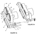
- FIGS. Figures 1a, 2a and 3a represent opposite positions, after rotation between 120 ° and 150 ° of the rods 10 and 11 and the element to be orientated 2, with respect to the positions illustrated in FIGS. Figures 1a, 2a and 3a .
- Figures 1a, 2a and 3a show the gripper 1 attached to the end of the support arm 3 by means of a pin 5 free rotation.
- Said clamp comprises retractable jaws 6 for grasping and holding the element to be oriented 2.
- the collet with retractable jaws 6 is equipped with a linear movement for gripping and releasing the element to be oriented 2. Closing and clamping of the jaws being performed at the end of the output stroke.
- the support arm 3 ensures the transmission of the movement from the rotation generator assembly 4 towards the gripper 1.
- the support arm comprises, in addition to the crankpin 5 which carries the gripping head 1, two crank pins 7 and 8 attached to the ends of two connecting rods. These crank pins are rotatably mounted in the support arm 3 to ensure the transmission of movement between the rotation generator assembly and the gripper.
- crank pins 5 and 7 It is further arranged on the crank pins 5 and 7, a device for transmitting and synchronizing the rotation of the gripping head 1.
- This transmission and synchronization device during the movement of the rods 10 and 11 may be constituted as illustrated in the figures by a set of pulleys carried by the crank pins 5 and 7 and a belt 9 or by any other known system.
- the rotation generator assembly comprises a set of two rods 10 and 11 mounted integral on a drive 12 and connected at their ends to the crank pins 7 and 8.
- the drive 12 is placed on a gear motor, for example, so as to generate a rotation as accurate and continuous as possible.
- the axes 13, 14, 15, 16, of the two connecting rods 10 and 11 form a parallelogram, one of the long sides of which is a part of the support arm 3.
- the distance d between the axes 13 and 16 being strictly equal to the distance between the axes 14 and 15.
- the main gears of the two connecting rods 10 and 11 engage a synchronized rotation having the effect of moving the support arm 3 parallel to itself in a global rotational movement .
- the axis 17 of the element to be oriented is parallel to the axes 13 and 14 and included in the plane formed by these two axes 13,14.
- the axes 15, 16 and 18 of the three pins 7, 8 and 5 are included in the same plane. During the movement, the plane formed by these three axes 15, 16 and 18 moves parallel to the fixed plane formed by the three axes 13, 14 and 17.
- the distance d between the axes 13, 16 or 14, 15 of the two connecting rods 10 and 11 is strictly identical to the distance between the axis 18 of the crankpin 5 of the gripper 1 and the axis 17 of the element to guide 2.
- the device according to the invention allows precise control of the rotation of the element to be oriented around the axis 17 passing through the center of the jaws 6. This rotation is possible between 0 and 360 ° so as to allow, in one or several subsequent steps, all possible bending configurations.
- the rotations of the rods 10 and 11 are carried out in one direction or the other so as to allow all the angular positions of the element to be oriented 2 around its axis 17.
- the device according to the invention is preferably used for gripping by the middle of the element to be oriented, it is however conceivable to position the orientation device for a different grip, as required.
- FIGS. 3a and 3b illustrate the change of orientation of a U-tube with invariance of the position of the axis 17 of the tube.
- the clamping force of the jaws and the various components of the orientation head are chosen according to the characteristics of the element to be oriented, in particular its weight and its dimensions.
- orientation device without departing from the scope of the invention, it may in particular be envisaged a different system for the opening mechanism, closing, tightening, loosening of the bar, and a different mode of synchronization of said mechanism according to the position in the rotation of the rods and the element to be oriented.
- the device is preferably designed for the orientation of bars, tubes or profiles in bending macnines however it could be envisaged to use the tool for other elements having sufficient rigidity and to be reoriented around an axis of rotation for multiple transformations, such as wires, cables or various objects.
Landscapes
- Engineering & Computer Science (AREA)
- Mechanical Engineering (AREA)
- Bending Of Plates, Rods, And Pipes (AREA)
- Manipulator (AREA)
- Shaping Of Tube Ends By Bending Or Straightening (AREA)
Claims (10)
- Ausrichtungsvorrichtung für Stangen, Rohre oder Profile, die in Biegemaschinen verwendet werden kann und einen Arm (3) aufweist, der ein Greifsystem (1) trägt, das mit einer Zange (6) versehen ist und auf einem Kurbelzapfen (5) angeordnet ist, gekennzeichnet durch das Vorliegen von zwei Kurbeln (10, 11) und dadurch, dass:- die zwei Kurbeln (10, 11) mit dem Arm (3) an zwei weiteren Kurbelzapfen (7, 8) verbunden sind, die drehfrei in Bezug auf den Arm (3) montiert sind,- die zwei Kurbeln (10, 11) gleichzeitig betätigt werden können und derart angeordnet sind, dass Achsen 13, 14, 15, 16 der zwei Kurbeln ein Parallelogramm bilden, in dem eine der großen Seiten ein Teil des Tragearms (3) ist,- mindestens eine Kurbel (10, 11) mittels einem der zwei weiteren Kurbelzapfen (7, 8) mit dem Kurbelzapfen (5), der das Greifsystem trägt, derart gekoppelt ist, dass sie die Greifvorrichtung (1) automatisch im Verlauf der Bewegung der Kurbeln (10, 11) in einer synchronisierten Drehung mitnimmt.
- Ausrichtungsvorrichtung für Stangen, Rohre oder Profile nach Anspruch 1, in der die Drehung des auszurichtenden Elements (2) zwischen 0 und 360° um die Achse (17), die die Mitte der Backe (6) durchläuft, regelbar ist.
- Ausrichtungsvorrichtung für Stangen, Rohre oder Profile nach Anspruch 1, in der die Achsen (13, 14) von zwei Hauptzahnrädern der Kurbeln (10, 11) und die Achse (17) des auszurichtenden Elements (2) sich auf derselben Ebene befinden.
- Ausrichtungsvorrichtung für Stangen, Rohre oder Profile nach Anspruch 3, in der der Achsabstand (d) jeder Kurbel (10, 11) mit dem Abstand zwischen der Achse (18) des Kurbelzapfens (5) der Greifzange (1) und der Achse (17) des auszurichtenden Elements (2) strikt identisch ist.
- Ausrichtungsvorrichtung für Stangen, Rohre oder Profile nach Anspruch 4, in der der Abstand (d) in Abhängigkeit von dem Platzbedarf des auszurichtenden Elements (2) einstellbar ist.
- Ausrichtungsvorrichtung für Stangen, Rohre oder Profile nach Anspruch 1, in der die zwei Kurbeln (10, 11) mittels eines einzigen Antriebs (12) und beispielsweise einer Getriebemotorvorrichtung betätigt werden.
- Ausrichtungsvorrichtung für Stangen, Rohre oder Profile nach Anspruch 6, in der sich die zwei gleichzeitig betätigten Kurbeln (10, 11) in zwei entgegengesetzten Richtungen bezogen auf die Drehrichtung des Antriebs (12) drehen können.
- Ausrichtungsvorrichtung für Stangen, Rohre oder Profile nach einem der vorhergehenden Ansprüche, in der die Greifvorrichtung (1) eine Zange mit einziehbaren Backen (6) ist, die mit einem Linearweg zum Greifen des auszurichtenden Elements (2) und zum Schließen und Anziehen der Backen (6) ausgestattet ist.
- Ausrichtungsvorrichtung für Stangen, Rohre oder Profile nach einem der vorhergehenden Ansprüche, in der die Kopplungsvorrichtung zwischen mindestens einem der zwei weiteren Kurbelzapfen (7, 8) und dem Kurbelzapfen (5), der das Greifsystem trägt, ein System mit Scheiben und einem Riemen (9) ist.
- Ausrichtungsvorrichtung für Stangen, Rohre oder Profile nach einem der vorhergehenden Ansprüche, in der das auszurichtende Element (2) ein Stück ist, das einem U entspricht.
Applications Claiming Priority (1)
| Application Number | Priority Date | Filing Date | Title |
|---|---|---|---|
| PCT/FR2006/000084 WO2007080236A1 (fr) | 2006-01-16 | 2006-01-16 | Dispositif d’orientation pour machine de cintrage |
Publications (2)
| Publication Number | Publication Date |
|---|---|
| EP1979111A1 EP1979111A1 (de) | 2008-10-15 |
| EP1979111B1 true EP1979111B1 (de) | 2009-12-02 |
Family
ID=36763819
Family Applications (1)
| Application Number | Title | Priority Date | Filing Date |
|---|---|---|---|
| EP06709091A Expired - Lifetime EP1979111B1 (de) | 2006-01-16 | 2006-01-16 | Ausrichtungsvorrichtung für eine biegemaschine |
Country Status (6)
| Country | Link |
|---|---|
| EP (1) | EP1979111B1 (de) |
| AT (1) | ATE450329T1 (de) |
| BR (1) | BRPI0621002A2 (de) |
| CA (1) | CA2631846A1 (de) |
| DE (1) | DE602006010909D1 (de) |
| WO (1) | WO2007080236A1 (de) |
Families Citing this family (1)
| Publication number | Priority date | Publication date | Assignee | Title |
|---|---|---|---|---|
| CN109570295A (zh) * | 2018-12-29 | 2019-04-05 | 张家港市剑泉工具制造有限公司 | 一种钳子快速折弯装置 |
Family Cites Families (3)
| Publication number | Priority date | Publication date | Assignee | Title |
|---|---|---|---|---|
| DE3211688C2 (de) * | 1982-03-30 | 1986-10-09 | Binder, Karl-Franz, 8077 Reichertshofen | Industrie-Roboter für Fertigungs- und/oder Montagezwecke |
| FR2622129B1 (fr) * | 1987-10-26 | 1990-03-02 | Delaite Jean Francois | Machine de conformation d'un troncon de fil ou de tube par pliages successifs |
| FR2739801B1 (fr) * | 1995-10-13 | 1998-01-02 | Leseure Michel | Perfectionnements aux manipulateurs plans a trajectoire figee ou programmable a tres haute cadence |
-
2006
- 2006-01-16 CA CA002631846A patent/CA2631846A1/fr not_active Abandoned
- 2006-01-16 EP EP06709091A patent/EP1979111B1/de not_active Expired - Lifetime
- 2006-01-16 WO PCT/FR2006/000084 patent/WO2007080236A1/fr not_active Ceased
- 2006-01-16 AT AT06709091T patent/ATE450329T1/de not_active IP Right Cessation
- 2006-01-16 BR BRPI0621002-3A patent/BRPI0621002A2/pt not_active Application Discontinuation
- 2006-01-16 DE DE602006010909T patent/DE602006010909D1/de not_active Expired - Lifetime
Also Published As
| Publication number | Publication date |
|---|---|
| DE602006010909D1 (de) | 2010-01-14 |
| BRPI0621002A2 (pt) | 2011-11-29 |
| ATE450329T1 (de) | 2009-12-15 |
| EP1979111A1 (de) | 2008-10-15 |
| CA2631846A1 (fr) | 2007-07-19 |
| WO2007080236A1 (fr) | 2007-07-19 |
Similar Documents
| Publication | Publication Date | Title |
|---|---|---|
| EP0445044B1 (de) | Rohrbiegevorrichtung mit zwei Biegeköpfen | |
| FR2575944A1 (fr) | Procede et dispositif pour le cintrage automatique de tubes metalliques | |
| WO2011144876A1 (fr) | Systeme de prehension d'objets fixes sur un ensemble robotise, comportant deux moyens de prehension | |
| FR2494165A1 (fr) | Dispositif pour saisir et manipuler des pieces d'oeuvre | |
| WO1985001898A1 (fr) | Machine automatique perfectionnee pour cambrer selon une configuration spatiale des elements minces et rectilignes, et notamment des fils metalliques | |
| EP1979111B1 (de) | Ausrichtungsvorrichtung für eine biegemaschine | |
| FR3121622A1 (fr) | Tete de prehension et de poinçonnage d’une piece permettant son entrainement en rotation pour son usinage | |
| FR3019073A1 (fr) | Presse a refouler et procede pour refouler une extremite de pieces oblongues | |
| FR2880561A1 (fr) | Dispositif d'orientation pour machine de cintrage | |
| EP0307293B1 (de) | Zusammenkuppelsystem für zwei Körper, z.B. einen Transportwagen und eine Bearbeitungsstation | |
| EP1311356B1 (de) | Vorrichtung zum biegen von rohren | |
| EP0220095B1 (de) | Verfahren und Vorrichtung zum Ausrichten und Anpassen eines ersten Teiles aus Kunststoff, das beispielsweise thermoverschweissbar mit einem zweiten ähnlichen Kunststoffteil ist, welches ebenfalls im Hinblick auf das Verbinden der Enden ausgerichtet werden kann | |
| FR2678116A1 (fr) | Pinces de manipulation de fil, procede et dispositif de fabrication de faisceaux electriques utilisant ces pinces. | |
| EP3088144B1 (de) | Lösung der änderung des abstands in einer angleichungsvorrichtung | |
| FR2537908A1 (fr) | Dispositif de prehension, notamment pour robot industriel | |
| EP1948371B1 (de) | Maschine zum wölben, formen, falzen oder biegen von stäben, drähten oder extrudierten formkörpern und diese einsetzendes verfahren | |
| FR3069857A3 (fr) | Systeme de commande de support telescopique d'une palette | |
| FR2708491A1 (fr) | Dispositif de préassemblage de deux pièces à sertir. | |
| BE1032890B1 (fr) | Dispositif de cintrage d'une pièce allongée | |
| EP1551587A2 (de) | Verfahren und vorrichtung zum abziehen und/oder wechseln von elektroden einer schweisszange oder eines schweissgerätes | |
| FR2890060A1 (fr) | Dispositif de transfert d'articles | |
| WO2012153025A1 (fr) | Mandrin de serrage | |
| FR2678136A1 (fr) | Procede et dispositif d'insertion d'extremites de fil dans des composants et dispositif de fabrication de faisceaux electriques. | |
| FR2826889A1 (fr) | Chariot pour machine a cintrer les tubes | |
| WO2024132847A1 (fr) | Pince, système et procédé d'insertion d'un objet au sein d'un rail et robot équipé d'une telle pince |
Legal Events
| Date | Code | Title | Description |
|---|---|---|---|
| PUAI | Public reference made under article 153(3) epc to a published international application that has entered the european phase |
Free format text: ORIGINAL CODE: 0009012 |
|
| 17P | Request for examination filed |
Effective date: 20080818 |
|
| AK | Designated contracting states |
Kind code of ref document: A1 Designated state(s): AT BE BG CH CY CZ DE DK EE ES FI FR GB GR HU IE IS IT LI LT LU LV MC NL PL PT RO SE SI SK TR |
|
| GRAP | Despatch of communication of intention to grant a patent |
Free format text: ORIGINAL CODE: EPIDOSNIGR1 |
|
| GRAS | Grant fee paid |
Free format text: ORIGINAL CODE: EPIDOSNIGR3 |
|
| GRAA | (expected) grant |
Free format text: ORIGINAL CODE: 0009210 |
|
| AK | Designated contracting states |
Kind code of ref document: B1 Designated state(s): AT BE BG CH CY CZ DE DK EE ES FI FR GB GR HU IE IS IT LI LT LU LV MC NL PL PT RO SE SI SK TR |
|
| REG | Reference to a national code |
Ref country code: GB Ref legal event code: FG4D Free format text: NOT ENGLISH |
|
| REG | Reference to a national code |
Ref country code: CH Ref legal event code: EP |
|
| REG | Reference to a national code |
Ref country code: IE Ref legal event code: FG4D |
|
| REF | Corresponds to: |
Ref document number: 602006010909 Country of ref document: DE Date of ref document: 20100114 Kind code of ref document: P |
|
| REG | Reference to a national code |
Ref country code: GR Ref legal event code: EP Ref document number: 20100400299 Country of ref document: GR |
|
| REG | Reference to a national code |
Ref country code: NL Ref legal event code: VDEP Effective date: 20091202 |
|
| PG25 | Lapsed in a contracting state [announced via postgrant information from national office to epo] |
Ref country code: SE Free format text: LAPSE BECAUSE OF FAILURE TO SUBMIT A TRANSLATION OF THE DESCRIPTION OR TO PAY THE FEE WITHIN THE PRESCRIBED TIME-LIMIT Effective date: 20091202 Ref country code: FI Free format text: LAPSE BECAUSE OF FAILURE TO SUBMIT A TRANSLATION OF THE DESCRIPTION OR TO PAY THE FEE WITHIN THE PRESCRIBED TIME-LIMIT Effective date: 20091202 Ref country code: LT Free format text: LAPSE BECAUSE OF FAILURE TO SUBMIT A TRANSLATION OF THE DESCRIPTION OR TO PAY THE FEE WITHIN THE PRESCRIBED TIME-LIMIT Effective date: 20091202 |
|
| LTIE | Lt: invalidation of european patent or patent extension |
Effective date: 20091202 |
|
| PG25 | Lapsed in a contracting state [announced via postgrant information from national office to epo] |
Ref country code: SI Free format text: LAPSE BECAUSE OF FAILURE TO SUBMIT A TRANSLATION OF THE DESCRIPTION OR TO PAY THE FEE WITHIN THE PRESCRIBED TIME-LIMIT Effective date: 20091202 Ref country code: CY Free format text: LAPSE BECAUSE OF FAILURE TO SUBMIT A TRANSLATION OF THE DESCRIPTION OR TO PAY THE FEE WITHIN THE PRESCRIBED TIME-LIMIT Effective date: 20091202 Ref country code: LV Free format text: LAPSE BECAUSE OF FAILURE TO SUBMIT A TRANSLATION OF THE DESCRIPTION OR TO PAY THE FEE WITHIN THE PRESCRIBED TIME-LIMIT Effective date: 20091202 Ref country code: PL Free format text: LAPSE BECAUSE OF FAILURE TO SUBMIT A TRANSLATION OF THE DESCRIPTION OR TO PAY THE FEE WITHIN THE PRESCRIBED TIME-LIMIT Effective date: 20091202 |
|
| PG25 | Lapsed in a contracting state [announced via postgrant information from national office to epo] |
Ref country code: AT Free format text: LAPSE BECAUSE OF FAILURE TO SUBMIT A TRANSLATION OF THE DESCRIPTION OR TO PAY THE FEE WITHIN THE PRESCRIBED TIME-LIMIT Effective date: 20091202 |
|
| REG | Reference to a national code |
Ref country code: IE Ref legal event code: FD4D |
|
| PG25 | Lapsed in a contracting state [announced via postgrant information from national office to epo] |
Ref country code: BG Free format text: LAPSE BECAUSE OF FAILURE TO SUBMIT A TRANSLATION OF THE DESCRIPTION OR TO PAY THE FEE WITHIN THE PRESCRIBED TIME-LIMIT Effective date: 20100302 Ref country code: ES Free format text: LAPSE BECAUSE OF FAILURE TO SUBMIT A TRANSLATION OF THE DESCRIPTION OR TO PAY THE FEE WITHIN THE PRESCRIBED TIME-LIMIT Effective date: 20100313 Ref country code: RO Free format text: LAPSE BECAUSE OF FAILURE TO SUBMIT A TRANSLATION OF THE DESCRIPTION OR TO PAY THE FEE WITHIN THE PRESCRIBED TIME-LIMIT Effective date: 20091202 Ref country code: PT Free format text: LAPSE BECAUSE OF FAILURE TO SUBMIT A TRANSLATION OF THE DESCRIPTION OR TO PAY THE FEE WITHIN THE PRESCRIBED TIME-LIMIT Effective date: 20100402 Ref country code: IE Free format text: LAPSE BECAUSE OF FAILURE TO SUBMIT A TRANSLATION OF THE DESCRIPTION OR TO PAY THE FEE WITHIN THE PRESCRIBED TIME-LIMIT Effective date: 20091202 Ref country code: IS Free format text: LAPSE BECAUSE OF FAILURE TO SUBMIT A TRANSLATION OF THE DESCRIPTION OR TO PAY THE FEE WITHIN THE PRESCRIBED TIME-LIMIT Effective date: 20100402 Ref country code: NL Free format text: LAPSE BECAUSE OF FAILURE TO SUBMIT A TRANSLATION OF THE DESCRIPTION OR TO PAY THE FEE WITHIN THE PRESCRIBED TIME-LIMIT Effective date: 20091202 Ref country code: EE Free format text: LAPSE BECAUSE OF FAILURE TO SUBMIT A TRANSLATION OF THE DESCRIPTION OR TO PAY THE FEE WITHIN THE PRESCRIBED TIME-LIMIT Effective date: 20091202 |
|
| PG25 | Lapsed in a contracting state [announced via postgrant information from national office to epo] |
Ref country code: SK Free format text: LAPSE BECAUSE OF FAILURE TO SUBMIT A TRANSLATION OF THE DESCRIPTION OR TO PAY THE FEE WITHIN THE PRESCRIBED TIME-LIMIT Effective date: 20091202 Ref country code: MC Free format text: LAPSE BECAUSE OF NON-PAYMENT OF DUE FEES Effective date: 20100131 Ref country code: CZ Free format text: LAPSE BECAUSE OF FAILURE TO SUBMIT A TRANSLATION OF THE DESCRIPTION OR TO PAY THE FEE WITHIN THE PRESCRIBED TIME-LIMIT Effective date: 20091202 |
|
| REG | Reference to a national code |
Ref country code: CH Ref legal event code: PL |
|
| PLBE | No opposition filed within time limit |
Free format text: ORIGINAL CODE: 0009261 |
|
| STAA | Information on the status of an ep patent application or granted ep patent |
Free format text: STATUS: NO OPPOSITION FILED WITHIN TIME LIMIT |
|
| PG25 | Lapsed in a contracting state [announced via postgrant information from national office to epo] |
Ref country code: CH Free format text: LAPSE BECAUSE OF NON-PAYMENT OF DUE FEES Effective date: 20100131 Ref country code: LI Free format text: LAPSE BECAUSE OF NON-PAYMENT OF DUE FEES Effective date: 20100131 |
|
| 26N | No opposition filed |
Effective date: 20100903 |
|
| PG25 | Lapsed in a contracting state [announced via postgrant information from national office to epo] |
Ref country code: DK Free format text: LAPSE BECAUSE OF FAILURE TO SUBMIT A TRANSLATION OF THE DESCRIPTION OR TO PAY THE FEE WITHIN THE PRESCRIBED TIME-LIMIT Effective date: 20091202 |
|
| PG25 | Lapsed in a contracting state [announced via postgrant information from national office to epo] |
Ref country code: LU Free format text: LAPSE BECAUSE OF NON-PAYMENT OF DUE FEES Effective date: 20100116 Ref country code: HU Free format text: LAPSE BECAUSE OF FAILURE TO SUBMIT A TRANSLATION OF THE DESCRIPTION OR TO PAY THE FEE WITHIN THE PRESCRIBED TIME-LIMIT Effective date: 20100603 |
|
| PG25 | Lapsed in a contracting state [announced via postgrant information from national office to epo] |
Ref country code: TR Free format text: LAPSE BECAUSE OF FAILURE TO SUBMIT A TRANSLATION OF THE DESCRIPTION OR TO PAY THE FEE WITHIN THE PRESCRIBED TIME-LIMIT Effective date: 20091202 |
|
| REG | Reference to a national code |
Ref country code: FR Ref legal event code: PLFP Year of fee payment: 11 |
|
| REG | Reference to a national code |
Ref country code: FR Ref legal event code: PLFP Year of fee payment: 12 |
|
| REG | Reference to a national code |
Ref country code: FR Ref legal event code: PLFP Year of fee payment: 13 |
|
| PGFP | Annual fee paid to national office [announced via postgrant information from national office to epo] |
Ref country code: GR Payment date: 20220127 Year of fee payment: 17 |
|
| REG | Reference to a national code |
Ref country code: DE Ref legal event code: R082 Ref document number: 602006010909 Country of ref document: DE Representative=s name: RAUCH, UDO, DIPL.-PHYS. DR. PHIL. NAT., DE |
|
| PG25 | Lapsed in a contracting state [announced via postgrant information from national office to epo] |
Ref country code: GR Free format text: LAPSE BECAUSE OF NON-PAYMENT OF DUE FEES Effective date: 20230804 |
|
| PGFP | Annual fee paid to national office [announced via postgrant information from national office to epo] |
Ref country code: DE Payment date: 20250116 Year of fee payment: 20 |
|
| PGFP | Annual fee paid to national office [announced via postgrant information from national office to epo] |
Ref country code: BE Payment date: 20250130 Year of fee payment: 20 |
|
| PGFP | Annual fee paid to national office [announced via postgrant information from national office to epo] |
Ref country code: FR Payment date: 20250115 Year of fee payment: 20 |
|
| PGFP | Annual fee paid to national office [announced via postgrant information from national office to epo] |
Ref country code: GB Payment date: 20250123 Year of fee payment: 20 Ref country code: IT Payment date: 20250109 Year of fee payment: 20 |
|
| REG | Reference to a national code |
Ref country code: DE Ref legal event code: R071 Ref document number: 602006010909 Country of ref document: DE |
|
| REG | Reference to a national code |
Ref country code: GB Ref legal event code: PE20 Expiry date: 20260115 |
|
| REG | Reference to a national code |
Ref country code: BE Ref legal event code: MK Effective date: 20260116 |