EP1979246B1 - Capot, en particulier pour des récipients pour une charge sensible à la corrosion - Google Patents
Capot, en particulier pour des récipients pour une charge sensible à la corrosion Download PDFInfo
- Publication number
- EP1979246B1 EP1979246B1 EP07704193A EP07704193A EP1979246B1 EP 1979246 B1 EP1979246 B1 EP 1979246B1 EP 07704193 A EP07704193 A EP 07704193A EP 07704193 A EP07704193 A EP 07704193A EP 1979246 B1 EP1979246 B1 EP 1979246B1
- Authority
- EP
- European Patent Office
- Prior art keywords
- hood
- film
- container
- corrosion inhibitor
- lid
- Prior art date
- Legal status (The legal status is an assumption and is not a legal conclusion. Google has not performed a legal analysis and makes no representation as to the accuracy of the status listed.)
- Not-in-force
Links
- 238000005260 corrosion Methods 0.000 title claims description 59
- 230000007797 corrosion Effects 0.000 title claims description 59
- 239000003112 inhibitor Substances 0.000 claims description 44
- 238000003860 storage Methods 0.000 claims description 42
- 239000004698 Polyethylene Substances 0.000 claims description 8
- -1 polyethylene Polymers 0.000 claims description 8
- 229920000573 polyethylene Polymers 0.000 claims description 8
- 239000000203 mixture Substances 0.000 claims description 3
- 150000002823 nitrates Chemical group 0.000 claims description 3
- 229910019142 PO4 Inorganic materials 0.000 claims description 2
- 150000001412 amines Chemical class 0.000 claims description 2
- 150000001558 benzoic acid derivatives Chemical class 0.000 claims description 2
- 150000001642 boronic acid derivatives Chemical class 0.000 claims description 2
- ZCDOYSPFYFSLEW-UHFFFAOYSA-N chromate(2-) Chemical class [O-][Cr]([O-])(=O)=O ZCDOYSPFYFSLEW-UHFFFAOYSA-N 0.000 claims description 2
- 150000002391 heterocyclic compounds Chemical class 0.000 claims description 2
- 238000012856 packing Methods 0.000 claims description 2
- 235000021317 phosphate Nutrition 0.000 claims description 2
- 150000003013 phosphoric acid derivatives Chemical class 0.000 claims description 2
- 150000004760 silicates Chemical class 0.000 claims description 2
- 239000000843 powder Substances 0.000 claims 1
- 238000003466 welding Methods 0.000 description 8
- 238000001125 extrusion Methods 0.000 description 7
- 239000012530 fluid Substances 0.000 description 7
- 239000006260 foam Substances 0.000 description 6
- 239000011888 foil Substances 0.000 description 6
- 238000004519 manufacturing process Methods 0.000 description 6
- 239000000463 material Substances 0.000 description 6
- 229920003023 plastic Polymers 0.000 description 6
- 239000004033 plastic Substances 0.000 description 6
- 238000004806 packaging method and process Methods 0.000 description 5
- 229920000642 polymer Polymers 0.000 description 5
- 238000009792 diffusion process Methods 0.000 description 4
- 229920000092 linear low density polyethylene Polymers 0.000 description 4
- 239000004707 linear low-density polyethylene Substances 0.000 description 4
- 150000001875 compounds Chemical class 0.000 description 3
- 238000005520 cutting process Methods 0.000 description 3
- 238000000034 method Methods 0.000 description 3
- 239000004712 Metallocene polyethylene (PE-MC) Substances 0.000 description 2
- 239000004708 Very-low-density polyethylene Substances 0.000 description 2
- 239000011324 bead Substances 0.000 description 2
- 239000000969 carrier Substances 0.000 description 2
- 229920001577 copolymer Polymers 0.000 description 2
- 239000008188 pellet Substances 0.000 description 2
- 239000002985 plastic film Substances 0.000 description 2
- 229920006255 plastic film Polymers 0.000 description 2
- 239000000047 product Substances 0.000 description 2
- LPXPTNMVRIOKMN-UHFFFAOYSA-M sodium nitrite Chemical compound [Na+].[O-]N=O LPXPTNMVRIOKMN-UHFFFAOYSA-M 0.000 description 2
- 239000007787 solid Substances 0.000 description 2
- 239000007858 starting material Substances 0.000 description 2
- 229920001866 very low density polyethylene Polymers 0.000 description 2
- XLYOFNOQVPJJNP-UHFFFAOYSA-N water Chemical compound O XLYOFNOQVPJJNP-UHFFFAOYSA-N 0.000 description 2
- 239000004594 Masterbatch (MB) Substances 0.000 description 1
- 239000000853 adhesive Substances 0.000 description 1
- 238000004026 adhesive bonding Methods 0.000 description 1
- 230000001070 adhesive effect Effects 0.000 description 1
- 230000002411 adverse Effects 0.000 description 1
- 239000003570 air Substances 0.000 description 1
- 239000012080 ambient air Substances 0.000 description 1
- 230000009286 beneficial effect Effects 0.000 description 1
- 230000015572 biosynthetic process Effects 0.000 description 1
- 239000012876 carrier material Substances 0.000 description 1
- 238000004040 coloring Methods 0.000 description 1
- NHFDKKSSQWCEES-UHFFFAOYSA-N dihydrogen phosphate;tris(2-hydroxyethyl)azanium Chemical compound OP(O)(O)=O.OCCN(CCO)CCO NHFDKKSSQWCEES-UHFFFAOYSA-N 0.000 description 1
- 238000006073 displacement reaction Methods 0.000 description 1
- 230000000694 effects Effects 0.000 description 1
- 238000010348 incorporation Methods 0.000 description 1
- 230000002401 inhibitory effect Effects 0.000 description 1
- 150000002826 nitrites Chemical class 0.000 description 1
- 239000011148 porous material Substances 0.000 description 1
- 239000002244 precipitate Substances 0.000 description 1
- 238000002360 preparation method Methods 0.000 description 1
- 238000011084 recovery Methods 0.000 description 1
- 239000005060 rubber Substances 0.000 description 1
- 238000007789 sealing Methods 0.000 description 1
- WXMKPNITSTVMEF-UHFFFAOYSA-M sodium benzoate Chemical compound [Na+].[O-]C(=O)C1=CC=CC=C1 WXMKPNITSTVMEF-UHFFFAOYSA-M 0.000 description 1
- 235000010234 sodium benzoate Nutrition 0.000 description 1
- 239000004299 sodium benzoate Substances 0.000 description 1
- 235000010288 sodium nitrite Nutrition 0.000 description 1
- 159000000000 sodium salts Chemical class 0.000 description 1
- 239000000126 substance Substances 0.000 description 1
- 229920001059 synthetic polymer Polymers 0.000 description 1
- 238000009827 uniform distribution Methods 0.000 description 1
Images


Classifications
-
- B—PERFORMING OPERATIONS; TRANSPORTING
- B65—CONVEYING; PACKING; STORING; HANDLING THIN OR FILAMENTARY MATERIAL
- B65D—CONTAINERS FOR STORAGE OR TRANSPORT OF ARTICLES OR MATERIALS, e.g. BAGS, BARRELS, BOTTLES, BOXES, CANS, CARTONS, CRATES, DRUMS, JARS, TANKS, HOPPERS, FORWARDING CONTAINERS; ACCESSORIES, CLOSURES, OR FITTINGS THEREFOR; PACKAGING ELEMENTS; PACKAGES
- B65D75/00—Packages comprising articles or materials partially or wholly enclosed in strips, sheets, blanks, tubes or webs of flexible sheet material, e.g. in folded wrappers
-
- B—PERFORMING OPERATIONS; TRANSPORTING
- B65—CONVEYING; PACKING; STORING; HANDLING THIN OR FILAMENTARY MATERIAL
- B65D—CONTAINERS FOR STORAGE OR TRANSPORT OF ARTICLES OR MATERIALS, e.g. BAGS, BARRELS, BOTTLES, BOXES, CANS, CARTONS, CRATES, DRUMS, JARS, TANKS, HOPPERS, FORWARDING CONTAINERS; ACCESSORIES, CLOSURES, OR FITTINGS THEREFOR; PACKAGING ELEMENTS; PACKAGES
- B65D81/00—Containers, packaging elements, or packages, for contents presenting particular transport or storage problems, or adapted to be used for non-packaging purposes after removal of contents
- B65D81/24—Adaptations for preventing deterioration or decay of contents; Applications to the container or packaging material of food preservatives, fungicides, pesticides or animal repellants
- B65D81/26—Adaptations for preventing deterioration or decay of contents; Applications to the container or packaging material of food preservatives, fungicides, pesticides or animal repellants with provision for draining away, or absorbing, or removing by ventilation, fluids, e.g. exuded by contents; Applications of corrosion inhibitors or desiccators
- B65D81/266—Adaptations for preventing deterioration or decay of contents; Applications to the container or packaging material of food preservatives, fungicides, pesticides or animal repellants with provision for draining away, or absorbing, or removing by ventilation, fluids, e.g. exuded by contents; Applications of corrosion inhibitors or desiccators for absorbing gases, e.g. oxygen absorbers or desiccants
- B65D81/267—Adaptations for preventing deterioration or decay of contents; Applications to the container or packaging material of food preservatives, fungicides, pesticides or animal repellants with provision for draining away, or absorbing, or removing by ventilation, fluids, e.g. exuded by contents; Applications of corrosion inhibitors or desiccators for absorbing gases, e.g. oxygen absorbers or desiccants the absorber being in sheet form
-
- B—PERFORMING OPERATIONS; TRANSPORTING
- B65—CONVEYING; PACKING; STORING; HANDLING THIN OR FILAMENTARY MATERIAL
- B65D—CONTAINERS FOR STORAGE OR TRANSPORT OF ARTICLES OR MATERIALS, e.g. BAGS, BARRELS, BOTTLES, BOXES, CANS, CARTONS, CRATES, DRUMS, JARS, TANKS, HOPPERS, FORWARDING CONTAINERS; ACCESSORIES, CLOSURES, OR FITTINGS THEREFOR; PACKAGING ELEMENTS; PACKAGES
- B65D81/00—Containers, packaging elements, or packages, for contents presenting particular transport or storage problems, or adapted to be used for non-packaging purposes after removal of contents
- B65D81/24—Adaptations for preventing deterioration or decay of contents; Applications to the container or packaging material of food preservatives, fungicides, pesticides or animal repellants
- B65D81/26—Adaptations for preventing deterioration or decay of contents; Applications to the container or packaging material of food preservatives, fungicides, pesticides or animal repellants with provision for draining away, or absorbing, or removing by ventilation, fluids, e.g. exuded by contents; Applications of corrosion inhibitors or desiccators
- B65D81/266—Adaptations for preventing deterioration or decay of contents; Applications to the container or packaging material of food preservatives, fungicides, pesticides or animal repellants with provision for draining away, or absorbing, or removing by ventilation, fluids, e.g. exuded by contents; Applications of corrosion inhibitors or desiccators for absorbing gases, e.g. oxygen absorbers or desiccants
- B65D81/268—Adaptations for preventing deterioration or decay of contents; Applications to the container or packaging material of food preservatives, fungicides, pesticides or animal repellants with provision for draining away, or absorbing, or removing by ventilation, fluids, e.g. exuded by contents; Applications of corrosion inhibitors or desiccators for absorbing gases, e.g. oxygen absorbers or desiccants the absorber being enclosed in a small pack, e.g. bag, included in the package
-
- B—PERFORMING OPERATIONS; TRANSPORTING
- B32—LAYERED PRODUCTS
- B32B—LAYERED PRODUCTS, i.e. PRODUCTS BUILT-UP OF STRATA OF FLAT OR NON-FLAT, e.g. CELLULAR OR HONEYCOMB, FORM
- B32B2307/00—Properties of the layers or laminate
- B32B2307/70—Other properties
- B32B2307/752—Corrosion inhibitor
-
- B—PERFORMING OPERATIONS; TRANSPORTING
- B32—LAYERED PRODUCTS
- B32B—LAYERED PRODUCTS, i.e. PRODUCTS BUILT-UP OF STRATA OF FLAT OR NON-FLAT, e.g. CELLULAR OR HONEYCOMB, FORM
- B32B2439/00—Containers; Receptacles
-
- B—PERFORMING OPERATIONS; TRANSPORTING
- B32—LAYERED PRODUCTS
- B32B—LAYERED PRODUCTS, i.e. PRODUCTS BUILT-UP OF STRATA OF FLAT OR NON-FLAT, e.g. CELLULAR OR HONEYCOMB, FORM
- B32B37/00—Methods or apparatus for laminating, e.g. by curing or by ultrasonic bonding
- B32B37/14—Methods or apparatus for laminating, e.g. by curing or by ultrasonic bonding characterised by the properties of the layers
- B32B37/15—Methods or apparatus for laminating, e.g. by curing or by ultrasonic bonding characterised by the properties of the layers with at least one layer being manufactured and immediately laminated before reaching its stable state, e.g. in which a layer is extruded and laminated while in semi-molten state
- B32B37/153—Methods or apparatus for laminating, e.g. by curing or by ultrasonic bonding characterised by the properties of the layers with at least one layer being manufactured and immediately laminated before reaching its stable state, e.g. in which a layer is extruded and laminated while in semi-molten state at least one layer is extruded and immediately laminated while in semi-molten state
-
- B—PERFORMING OPERATIONS; TRANSPORTING
- B65—CONVEYING; PACKING; STORING; HANDLING THIN OR FILAMENTARY MATERIAL
- B65D—CONTAINERS FOR STORAGE OR TRANSPORT OF ARTICLES OR MATERIALS, e.g. BAGS, BARRELS, BOTTLES, BOXES, CANS, CARTONS, CRATES, DRUMS, JARS, TANKS, HOPPERS, FORWARDING CONTAINERS; ACCESSORIES, CLOSURES, OR FITTINGS THEREFOR; PACKAGING ELEMENTS; PACKAGES
- B65D2203/00—Decoration means, markings, information elements, contents indicators
- B65D2203/10—Transponders
Definitions
- the present invention relates to a hood according to the preamble of claim 1, in particular for sealing storage or transport containers for receiving corrosion-sensitive charge.
- Containers for the storage and / or transport of corrosion-sensitive cargo are known for various applications.
- such containers are used in large numbers in order to enable a rational and automatable storage of a variety of different parts.
- Such containers also referred to as small load carriers (KLT)
- KLT small load carriers
- Such containers also referred to as small load carriers (KLT)
- KLT small load carriers
- To seal such containers are both hoods of flexible films as well as rigid lid.
- VCI Volatile Corrosion Inhibitors
- An RFID-enabled container which comprises a container blank and an RF transponder which is arranged on the container blank so that it is not visible from the outside when the container is set up.
- the object of the present invention is to provide a hood with the help of which a quick and easy identification of the charge located in the container is made possible.
- a hood according to claim 1 characterized in that the hood comprises an electronic memory element.
- Hoods with an electronic memory element can also be used for the packaging of general cargo, such as motors or gearboxes. With the help of the memory element, the content be identified at any time without the packaging being opened, thereby impairing the corrosion protection. As a result, for example, inventory or customs clearance of goods are much easier.
- the storage element can be used to store any type of relevant data, in particular the type and quantity of the contents of the container, exact type designations, the date of storage or the destination during transport.
- the storage element can also serve to track the transport path of the goods.
- An electronic memory element makes it possible to store a large amount of data in a very small space, for example compared to a label.
- an electronic memory chip can be read out and / or written by machine so that these processes can also be carried out automatically.
- the memory element is preferably read without contact. This is the case in particular with the aid of so-called RFID chips (Radio Frequency IDentification), which can be read out by radio.
- RFID chips Radio Frequency IDentification
- the memory element can also be written without contact, so that the data stored in the element can be updated if necessary in a simple manner. This applies in particular to the above-mentioned lifetime of the corrosion protection, which is affected by repeated opening of the container and which can then be updated accordingly with each opening.
- the storage element is preferably permanently connected to the hood. This can prevent data loss by removing or dropping the memory element.
- the storage element is welded onto the hood. A detachment of the memory element is thereby virtually eliminated.
- the storage element may in particular also be welded in a weld seam of the hood.
- the storage element can be glued to the hood.
- a sticking can be particularly beneficial if a Aufschwei- ⁇ en due to the materials of the storage element and the hood is not possible.
- the electronic memory element preferably comprises an electronic memory chip and a carrier, on which the memory chip is arranged.
- the memory chip and / or also an RFID chip can be enclosed in the carrier or adhered to it.
- the carrier itself is in turn preferably glued or welded onto the hood.
- a hood based on polyethylene such a support is preferably produced based on polyethylene.
- the electronic storage element is arranged on the container itself.
- the subject of the invention is therefore also a storage or transport container of the type mentioned, which comprises an electronic storage element.
- the arrangement of the storage element on the container in the same manner and according to the same embodiments, as described in connection with the hood according to the invention.
- the present invention relates to a hood of the type mentioned, which is made of a film containing at least one volatile corrosion inhibitor.
- the hood according to the invention which defines an interior space and has an opening, is slipped with its opening over the storage or transport container.
- the container is thereby closed, and at the same time the corrosion inhibitor contained in the film is delivered to the interior of the container.
- corrosion protection of the charge contained in the container is ensured even during a longer storage time.
- the corrosion inhibitor contained in the film is exhausted, the hood is replaced.
- the remaining life of the corrosion inhibitor can be determined at any time.
- hood is made of a film containing corrosion inhibitor (s), which is elastically extensible.
- a film is referred to as elastically extensible if, after stretching of the film, at least predominantly a return to the original dimension takes place.
- Hoods made of an elastically stretchable film have significant advantages over the previously used VCI-containing hoods.
- the elastic hood according to the invention preferably consists only of the film and can thus be produced in a simple manner by machine. This leads to a significant cost savings compared to the previously known hoods.
- the elastic hood according to the invention When closing containers or when packing piece goods for the purpose of storage or transport, the elastic hood according to the invention is usually stretched, so that it rests tightly on the packaged object due to the high elastic restoring force. On the one hand, this reduces the risk of the film sticking out of the object and being damaged during transport, and, on the other hand, ensuring high tightness of the packaging. Especially from the point of view of corrosion protection, it is desirable that the packaging is as airtight as possible, which is made possible to a high degree by the use of an elastic hood according to the invention.
- the elongation of the film along the opening of the hood is usually up to 10% (so-called use stretch).
- the tightness of the hood against air and water vapor can be further increased by the fact that along the opening of the hood by pushing together the film forms a bead, which exerts a correspondingly greater pressure on the container.
- the extensibility of the film, from which the elastic hood according to the invention is made can be characterized inter alia by their elongation at break, that is, by their maximum elongation to the crack.
- the elongation at break of the film is 300% or more, more preferably 600% or more.
- the recovery strain is preferably 50% or more, more preferably 100% or more.
- the film is further distinguished by the fact that its elasticity or resilience in elastically stretched state over a longer period of time, typically at least 8 to 10 weeks, is maintained.
- the thickness of the film is preferably in the range from 40 to 150 ⁇ m, in particular in the range from 50 to 80 ⁇ m.
- the special properties of the elastically stretchable film also offer the advantage that the hood produced therefrom has a high puncture resistance perpendicular to the material plane.
- the elastic hood according to the invention thus offers good protection against external mechanical effects on the packaged item.
- the elastically extensible film is preferably a plastic film which is produced on the basis of a synthetic polymer.
- different polymers can be considered as starting material, with which the mechanical properties described above can be realized.
- the film is made on the basis of polyethylene or polyethylene copolymers. These polymers are very suitable for the production of films, in particular by means of the extrusion process.
- Particularly suitable starting materials for the film are linear low-density polyethylene (LLD-PE), very low-density polyethylene (VLD-PE) or corresponding copolymers. Due to their molecular structure, these polymers lead to films with a high elastic stretchability.
- the polyethylenes used may additionally be metallocene polyethylene (mPE) or corresponding copolymers.
- the film comprises two or more layers.
- the at least one volatile corrosion inhibitor is contained at least in that layer of the film which faces the interior of the hood, so that the corrosion inhibitor is discharged exclusively or predominantly in the direction of the container contents or the packaged piece goods and not to the environment.
- multilayer films are also particularly advantageous because one or more additional layers which contain no corrosion inhibitor, the inventive elastic extensibility and the high tensile strength of the film can be further improved. These properties result primarily from the molecular structure of the film, which by the addition of the corrosion inhibitor is affected in the appropriate position. Layers without corrosion inhibitor also contribute in particular to a high airtightness and water vapor tightness of the film.
- the layers of a two- or multi-layer elastically extensible film are preferably coextruded.
- the coextrusion of multilayer films can be realized by means of various extrusion processes, in particular by blown film extrusion.
- the at least one volatile corrosion inhibitor is preferably present in finely powdered form in the film. This can be achieved, in particular, by adding the at least one volatile corrosion inhibitor to the polymer melt prior to extrusion of the film in polymer-bound form (compounded). This so-called masterbatch ensures the finest possible and uniform distribution of the at least one corrosion inhibitor in the film.
- the at least one volatile corrosion inhibitor is selected from nitrates, nitrites, phosphates, silicates, borates, chromates, molybdates, amines, benzoates, heterocyclic compounds, and mixtures thereof.
- the sodium salts of the compounds mentioned are preferably used in each case.
- the film from which the hood according to the invention is made is advantageously colored translucent. Such a coloring can serve for the identification of packaged objects, without having to dispense with a transparency of the hood.
- the hood of the invention may be made of one or more pieces of film, wherein the film piece (s) is folded and / or superposed and congruent edges of the film piece (s) are partially welded together.
- the non-welded edges of the foil pieces (s) form the opening with which the hood can be pulled over the container.
- the seams formed during welding offer a preferred possibility of connecting the electronic storage element to the hood by welding the storage element into a weld seam of the hood.
- the hood In order to avoid undesired protrusion of the hood, it is preferred if its shape is adapted to the shape of the storage or transport container. In principle, different shapes are conceivable for such containers, for example a cuboid or a cylindrical shape.
- the hood also has a cuboid shape. This can be achieved in particular in that the film is folded on the opposite side of the opening of the hood in the direction of the interior.
- the hood is made of a film tube, wherein the film for producing the hood along two opposite areas along the longitudinal axis of the tube is folded in the direction of the interior of the tube, and wherein the film tube is welded at one end, that the folded regions of the film with the non-folded portions of the film are four-layer welded.
- Hoods of this type are particularly easy to produce by folding in a continuous film tube produced by blown film extrusion as described above and then cutting at predetermined intervals and welding along the cutting edge. All work steps can be carried out continuously and automatically.
- the hood produced in this way can be brought into a cuboid shape, wherein the previously folded-in areas of the film form two opposite sides of the hood.
- the weld seam then runs along a center line of the side of the hood opposite the opening, wherein the sections of the previously folded-in regions adjacent to the weld are folded in the direction of the interior of the hood in such a way that two triangular regions in which the film comes to lie three-fold, be formed.
- a similar hood can, alternatively to the use of a hose, also be made of two equal rectangular pieces of film along in each case three of their edges are welded together to form a central weld and two subsequent side welds; the hood having two central fold lines, each running at an identical distance to both sides parallel to the central weld, having two lateral fold lines each running the same identical distance to both sides parallel to the side welds, and having four diagonal fold lines from the four intersections of the middle fold lines with the lateral fold lines to the respective adjacent end of the middle weld run; wherein the film is folded by 180 ° along the diagonal fold lines and along those portions of the lateral fold lines that lie between the intersections with the middle fold lines, so that in each case two triangular foil areas come to lie congruently on one another; and wherein the film is folded by 90 ° along the central fold lines and along those portions of the side fold lines which are outside the intersection with the central fold lines, so that the hood has a parallelepiped shape.
- the present invention also relates to the use of a hood as described above for closing storage or transport containers.
- a lid is understood in particular to mean a substantially rigid element with which the container can be detachably closed.
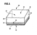
- FIG. 1 A first embodiment of a hood according to the invention is shown in perspective in FIG. 1 and denoted there by 10. Furthermore, the shows FIG. 1 a storage or transport container 12, a receiving space 13th defined and having an opening 14 which is closed by the hood 10. The parts of the container 12, which are covered by the hood 10, are shown here for the sake of clarity with dashed lines.
- the hood 10 is preferably transparent.
- Both the container 12 and the hood 10 have a substantially cuboid shape.
- the container 12 may be, for example, a small load carrier (KLT), as it often comes in the context of industrial storage used.
- KLT small load carrier
- the hood 10 is made of a film which comprises at least one volatile corrosion inhibitor and is elastically extensible.
- this film may be made of a linear low-density polyethylene (LLD-PE).
- LLD-PE linear low-density polyethylene
- the film has a high elastic elasticity and restoring force.
- the film is a three-layer, coextruded film having an elongation at break in the range of 650 to 750% and an elastic elongation in the range of 50 to 100%.
- the at least one corrosion inhibitor is contained only in that position of the film, which faces the interior 15 of the hood 10.
- the corrosion inhibitor may be the compounds mentioned above or mixtures thereof, such as sodium benzoate, sodium nitrite or triethanolamine phosphate.
- the circumference of the hood 10 along its opening 16, in the unstretched state of the film is smaller than the circumference of the container 12 in a plane parallel to its bottom surface 18. Therefore, the hood 10 is located on the side walls 20 of the container 12 due to the elastic restoring force the film firmly. Furthermore, the height of the hood 10, that is, the dimension selected perpendicular to the bottom surface 18, greater than the height of the side walls 20, so that the film along the opening 16 of the hood 10 by gathering a bead 22 forms. This additionally ensures an airtight closure of the container 12.
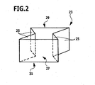
- the hood 10 may be made of a film tube 23, which in the FIG. 2 is shown schematically.
- a film tube 23 can be produced in particular by means of blown film extrusion.
- the film is first folded along two opposite regions 25 along the longitudinal axis of the tube 23 in the direction of the interior 27 of the tube 23. Subsequently, the film tube 23 is welded at one end 29 such that the folded-in regions 25 of the film are welded in four layers to the non-folded regions of the film (in the US Pat FIG. 2 not shown).
- the opposite, non-welded end 31 of the tube 23 forms the opening 16 of the hood 10th
- the extrusion of a continuous film tube, the cutting of individual film tubes 23 and the welding at their ends 29 can be carried out continuously and automatically.
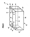
- the film tube 23 welded in this way can be brought into the essentially parallelepiped shape of the hood 10, as shown in FIG FIG. 3 is shown.
- the previously folded-in areas 25 of the film form two opposite sides 25 of the hood 10.
- the weld 33 formed by welding the end 29 of the hose 23 extends along a center line of the opening 14 opposite side 35 of the hood 10, wherein the weld 33 adjacent Sections of the previously folded-in areas 25 are folded in the direction of the interior 15 of the hood, that two triangular areas 37, in which the film comes to rest three-fold, are formed.
- a second embodiment of a hood according to the invention with a substantially cuboid shape can also be produced by welding and folding two rectangular pieces of film, as described below with reference to FIGS FIGS. 4 and 5 is described.
- FIG. 5 shows a perspective view of the second embodiment of the hood, which is designated as a whole by 39, including the welds and folded portions of the film.
- the film pieces 24 and 26 used for the production of the hood 39 are in the FIG. 4 shown in outstretched form.
- the two equal-sized, rectangular pieces are first welded together along a central weld seam 28 at one of their edges.
- the edges 30 and 32 of the first piece of film 24 adjacent to the central weld seam 28 are also welded to the corresponding edges 34 and 36 of the second piece of film 26, forming the in FIG. 3 shown side welds 38 and 40.
- the opposite of the central weld 28 edges 42 and 44 form the opening 16 of the hood 39th
- the film pieces 24 and 26 are folded to form the hood 39 along the following folding lines (in FIG. 4 shown by dashed lines), wherein the course of the fold lines refers to the spread in a plane pieces of film 24 and 26: two middle fold lines 46 each at an identical distance to both sides parallel to the central weld 28, two lateral fold lines 48 each extend in the same identical distance to both sides parallel to the lateral welds 38 and 40, and four diagonal fold lines 50 each extend from the four intersections of the middle Fold lines 46 with the side fold lines 48 to the respective adjacent end of the central weld 28th
- the film is folded by 180 ° so that two triangular foil areas 52 come to lie congruently on each other.
- the film is folded by 90 °, so that the hood 39, the in FIG. 5 having shown cuboid shape.
- the sections 48 "form the four edges of the hood 39 perpendicular to the opening 16, and the sections 48 'form two mutually parallel edges of the hood 39 opposite the opening 16. Two further parallel edges, which are opposite the opening 16 and perpendicular to the sections 48 'are formed by those portions 46' of the middle fold lines 46 which lie between the intersections with the lateral fold lines 48.
- FIG. 6 schematically shows two stacked containers 54 and 56 in lateral cross-section. The slipping of the upper container 54 is prevented by a projection 58 engages on the underside of the container 54 between the side walls 60 and 62 of the lower container 56 and thereby rests on projections 64 and 66.
- the lower container 56 is closed here with a hood 68, which corresponds to the hood 10 of the first embodiment.
- the hood 68 is thereby pressed by the projection 58 of the container 54 partially in the direction of the receiving space 69 of the container 56, which is easily possible due to the elastic extensibility of the film used for the hood 68 without the risk that the film tears.
- the same advantage also results in other configurations of the positive connection between the containers, since this will always be associated with stretching of the film.
- a third embodiment of a hood according to the invention is in the FIG. 7 shown in perspective and designated there as a whole with 70.
- the hood 70 is made of a film containing at least one volatile corrosion inhibitor, as in the hood 10 of the first embodiment.
- the hood 70 includes an electronic memory element 72 that is welded into a weld 74 of the hood 70.
- various data can be stored, which with respect to a the hood 70 are closed container relevant, in particular type and amount of the contents of the container, the date of storage, etc.
- the memory element 72 may comprise, for example, an RFID chip which can be read out and written by radio without contact. In this way, different containers can be uniquely identified at any time and the relevant data updated as needed.
- the electronic memory element 72 may also be connected to the foil in another way.
- a memory chip may be glued directly to the foil or secured in or on a carrier by welding or gluing.
- a carrier can in turn be glued or welded onto the film, wherein the film and the carrier are preferably made of the same material, in particular polyethylene.
- FIG. 8 is a container that can be used for storage and transport of small cargo, shown schematically and designated 110 as a whole.
- the container 110 which is preferably made of plastic, has a cuboid shape and comprises a rectangular bottom surface 112 and four of the bottom surface 112 vertically upwardly extending, rectangular, in pairs parallel side walls 114.
- the container 10 defines an interior 116 and has an opening 117 which is formed by the upper edges of the side walls 114.
- a lid 118 suitable for closing the opening 117 of the container 110 is shown in FIG FIG. 8 shown in a slightly raised position above the container 110.
- the lid 118 is substantially rectangular and is preferably made of a plastic material, as well as the container 110.
- a holding device and / or a receiving space, which are arranged on the lid 118, are due to the selected perspective in the FIG. 8 not visible. Possible embodiments of the lid 118 will be apparent from the four embodiments, which in the FIGS. 9 to 12 are shown and described below.
- the figures each show a lid and optionally a container in a sectional view, wherein the sectional plane corresponds to a plane of symmetry of the container 110.
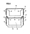
- FIG. 9 A corresponding sectional view of the container 110, the opening 117 is closed with a first embodiment of a lid 120 is in the FIG. 9 shown.
- the cover 120 rests on strip-shaped projections 122, which are integrally formed on at least two opposite side walls 114 and parallel to the opening 117 forming edges of the side walls 114 extend.
- the projections 122 are arranged in a distance approximately corresponding to the thickness of the cover 120 to the opening 117, so that the lid terminates approximately flush with the side walls 114 and the interior 116 of the container 110 is limited upwards.
- a holding device 124 is arranged at the interior 116 of the lid 120 facing side, that is the inside 123.
- This holding device 124 comprises two clamping elements 126 in the form of cuboid or strip-shaped projections, which are arranged at a distance from one another and which protrude at a right angle from the inside 123 of the lid 120.
- the clamping elements 126 define a receiving space 127 lying between them, wherein a fluid connection 129 between this receiving space 127 and the interior 116 of the container 110 by the unlocked, is defined from the inside 123 facing away side of the receiving space 127.
- a support member 128 containing at least one volatile corrosion inhibitor is arranged in the receiving space 127.
- this carrier element 128, the embodiment shown is a foam which is dimensioned in such a way that it is held non-positively, ie under tension, between the two clamping elements 126.
- the corrosion inhibitor contained in the foam can diffuse out of the foam through the pore structure of the foam, diffuse further through the fluid connection 129 into the interior 116 of the container 110 and distribute itself uniformly there.
- another carrier element may also be used, for example a tablet, a pellet or the like, with a corrosion inhibitor contained therein.
- the size of the tablet and the distance between the clamping elements 126 are each chosen so that the tablet is inserted under tension into the receiving space 127 and frictionally held between the clamping elements 126.
- the corrosion inhibitor can diffuse out of the support element 128, ie the tablet, which is in the holding position, and out of the container 116 via the fluid connection 129 into the interior 116 of the container 110.
- the holding device 124 also comprises two clamping elements 132.
- the clamping elements 132 are spaced from each other on the inside 123 of the lid 130 and have an approximately L-shaped configuration. First portions of the clamping elements 132 extend approximately at right angles from the inside 123 of the lid 130 away. Subsequent second subregions of the clamping elements 132 extend parallel to the lid, wherein free ends of the second portions of the two clamping elements 132 are oriented toward each other.
- the clamping elements 132 define a receiving space 134 lying between them and the inside 123 of the cover 130, which has a fluid connection 135 in the form of an outlet gap to the interior of a container, not shown in the figure.
- a support member 128 which is inserted between the two clamping elements 132 is held in this way in the receiving space 134 between the cover 130 and the clamping elements 132.
- One or more corrosion inhibitors contained in the support member 128 may diffuse via the fluid connection 135 into the interior of the container.
- the clamping elements 132 are, like the clamping elements 126 of the first embodiment, preferably formed integrally with the cover 130.
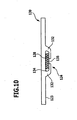
- a third embodiment of a lid is in the FIG. 11 shown in cross-section and designated 140 there.
- the lid 140 is substantially solid, but has an approximately cuboid recess, which defines a receiving space 142 for a support member 128. While the receiving space 142 is completely closed towards the outside 143 of the lid, it is bounded towards the inside 123 by a support element 144, which is formed integrally with the lid 140.
- the support element 144 forms an approximately rectangular surface, runs parallel to the inside 123 of the lid 140 and terminates flush with this. Along at least one of its four edges, the support element 144 is not connected to the lid 140, but spaced therefrom, so that a filling opening 145 of the receiving space 142 is formed. Through the filling opening 145, the support member 128 between the support member 144 and the cover 140, that is, in the receiving space 142, can be inserted.
- the support element 144 serves as a holding device 124.
- the support element 144 has openings 146.
- the openings 146 in addition to the filling opening 145, the fluid connection between the receiving space 142 and the interior 116 of the container 110. This may be a few openings 146, as in the FIG. 11 represented, or a variety of breakthroughs. It is particularly advantageous if the support element 144 is designed in the form of a grid.
- the carrier element 128 can also be, for example, a foam, a tablet or a pellet. Likewise, however, the carrier element 128 may also include, for example, a plastic sheath through which a corrosion inhibitor contained therein may diffuse.
- the lid 140 Due to the formation of the receiving space 142 in a recess of the lid 140, the lid 140 has an overall substantially planar shape, whereby a good stackability of a plurality of similar lid 140 is favored.
- the latter is substantially gas-tight enclosure, since the openings 146 and the filling opening 145 are closed by the outside 143 of the underlying lid 140. This will cause outdiffusion of the corrosion inhibitor during storage of the lid 140 largely prevented.
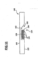
- a fourth embodiment of a lid is in the FIG. 12 shown in cross-section and designated there by 150.
- a receiving space 154 is likewise provided, which is formed by a substantially parallelepiped-shaped recess in the otherwise solid lid 150.
- the substantially rectangular support element 144 is formed integrally with the cover 150 and, in contrast to the third embodiment, connected to the cover 150 along all four edges.
- a fluid connection between the receiving space 154 and the interior of the container is therefore formed only by the apertures 146 provided in the support element 154.
- the support element 154 may be formed in this case in the form of a grid.
- the receiving space 154 Towards the outside 143 of the cover 150, the receiving space 154 has a filling opening 152, which is essentially rectangular and which lies opposite the support element 144. Through the filling opening 152, a carrier element 128, which substantially fills the receiving space 154, can be easily inserted into it.
- the filling opening 152 can be closed by a closure element 156 in the form of a pivotable flap, which is articulated on the outside 143 of the lid 150. In the closed position of the flap, outward diffusion of the corrosion inhibitor is prevented.
- the cover 150 offers the advantage that a carrier element 128 with depleted corrosion inhibitor can be exchanged through the filling opening 152 without the container having to be opened.
- the lid is a rigid closure member made of a substantially inflexible plastic material. Nevertheless, a receiving space and / or a holding device, as described above, can also be provided on the side of the hood facing the interior of the container, even in the case of a hood according to the invention which is entirely or partially made of a flexible film.
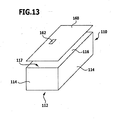
- FIG. 13 shows a perspective view of the already in FIG. 8 shown container 110 with a fifth embodiment of a lid, which is shown in a slightly raised position above the container 110 and designated by 160.
- the lid 160 may optionally include a holding device and / or a receiving space as in the covers 120, 130, 140 or 150.
- the lid 160 includes an electronic storage element 162 which is glued or welded on the outside of the lid 160.
- various data relevant to the container 110 may be stored, for example, the type and amount of the load and / or the date of storage.
- the storage element 162 can also store the use date of a corrosion inhibitor which is present in a carrier element on the lid 160 or which is present in the container 110 in any other form.
- the memory element 162 comprises a carrier 164, in which an electronic memory chip 166 is welded.
- the carrier 164 is preferably made of plastic, in particular of the same plastic material as the lid 160, whereby it is possible to weld it onto the lid 160. Likewise, an adhesive bond between the memory chip 166 and the carrier 164 and between the carrier 164 and the lid 160 is possible.
- the memory element 162 may further comprise an RFID chip 168, which allows a non-contact readout of the stored data via radio.
- the memory chip 166 and the RFID chip 168 may also be formed as a unit. By using RFID chips, different containers can be identified quickly and easily and the relevant data can be updated as needed.
- the electronic storage element may also be provided on the container 110, for example on one of the side walls 114 or on the bottom surface 112.
Landscapes
- Engineering & Computer Science (AREA)
- Mechanical Engineering (AREA)
- Food Science & Technology (AREA)
- Packages (AREA)
Claims (11)
- Couvercle (10 ; 39 ; 70) définissant un espace intérieur (15) et présentant une ouverture (16), prévu en particulier pour la fermeture de conteneurs de stockage ou de transport (12) destinés à recevoir une charge sensible à la corrosion, ledit couvercle (10 ; 39 ; 70) comprenant un élément de mémoire (72) électronique, caractérisé en ce que ledit couvercle (10 ; 39 ; 70) est fabriqué dans une feuille comprenant au moins un inhibiteur de corrosion volatil.
- Couvercle (10 ; 39 ; 70) selon la revendication 1, caractérisé en ce que l'élément de mémoire (72) est raccordé de manière inamovible au couvercle (10 ; 39 ; 70).
- Couvercle (10 ; 39 ; 70) selon la revendication 1 ou 2, caractérisé en ce que la durée de vie et/ou la date d'utilisation de l'inhibiteur de corrosion volatil sont sauvegardés dans l'élément de mémoire (72).
- Couvercle (10 ; 39 ; 70) selon l'une des revendications précédentes, caractérisé en ce que la feuille est élastiquement extensible.
- Couvercle (10 ; 39 ; 70) selon l'une des revendications précédentes, caractérisé en ce que la feuille présente une épaisseur de 40 à 150 µm.
- Couvercle (10 ; 39 ; 70) selon l'une des revendications précédentes, caractérisé en ce que la feuille est fabriquée à base de polyéthylène ou de copolymères de polyéthylène.
- Couvercle (10 ; 39 ; 70) selon l'une des revendications précédentes, caractérisé en ce que ledit couvercle (10 ; 39 ; 70) est fabriqué dans une feuille de deux ou de plusieurs couches, le ou les inhibiteurs de corrosion volatils étant contenus au moins dans la couche de la feuille qui fait face à l'espace intérieur (15).
- Couvercle (10 ; 39 ; 70) selon l'une des revendications précédentes, caractérisé en ce que le ou les inhibiteurs de corrosion volatils sont contenus sous forme de poudre fine dans la feuille.
- Couvercle (10 ; 39 ; 70) selon l'une des revendications précédentes, caractérisé en ce que le ou les inhibiteurs de corrosion volatils sont sélectionnés entre des nitrates, nitrures, phosphates, silicates, borates, chromates, molybdates, amines, benzoates, composés hétérocycliques, et des mélanges de ceux-ci.
- Utilisation d'un couvercle (10 ; 39 ; 70) selon l'une des revendications précédentes pour la fermeture de conteneurs de stockage ou de transport (12).
- Utilisation d'un couvercle (10 ; 39 ; 70) selon l'une des revendications 1 à 9 pour l'emballage de marchandises de détail.
Applications Claiming Priority (3)
| Application Number | Priority Date | Filing Date | Title |
|---|---|---|---|
| DE200610005666 DE102006005666A1 (de) | 2006-01-31 | 2006-01-31 | Folie sowie hieraus hergestellte Haube |
| DE200610014551 DE102006014551A1 (de) | 2006-03-20 | 2006-03-20 | Deckel zum Verschließen eines Behälters, insbesondere für korrosionsempfindliche Ladung |
| PCT/EP2007/050838 WO2007088155A1 (fr) | 2006-01-31 | 2007-01-29 | Capot ou couvercle, en particulier pour des récipients pour une charge sensible à la corrosion |
Publications (2)
| Publication Number | Publication Date |
|---|---|
| EP1979246A1 EP1979246A1 (fr) | 2008-10-15 |
| EP1979246B1 true EP1979246B1 (fr) | 2013-01-23 |
Family
ID=37945863
Family Applications (1)
| Application Number | Title | Priority Date | Filing Date |
|---|---|---|---|
| EP07704193A Not-in-force EP1979246B1 (fr) | 2006-01-31 | 2007-01-29 | Capot, en particulier pour des récipients pour une charge sensible à la corrosion |
Country Status (4)
| Country | Link |
|---|---|
| US (1) | US8348058B2 (fr) |
| EP (1) | EP1979246B1 (fr) |
| DK (1) | DK1979246T3 (fr) |
| WO (1) | WO2007088155A1 (fr) |
Families Citing this family (22)
| Publication number | Priority date | Publication date | Assignee | Title |
|---|---|---|---|---|
| DE102009013267A1 (de) * | 2009-03-06 | 2010-09-09 | Arnold Umformtechnik Gmbh & Co. Kg | Verpacken von Schüttgütern |
| CA2674761C (fr) | 2009-03-13 | 2016-10-04 | G.B.D. Corp. | Appareil de nettoyage de surfaces a configurations de nettoyage multiples |
| US8354441B2 (en) * | 2009-11-11 | 2013-01-15 | Hoffmann-La Roche Inc. | Oxazoline derivatives |
| FR2955800B1 (fr) * | 2010-02-04 | 2012-09-07 | Ctci | Un materiau composite thermoformable et sa methode de fabrication |
| US8963720B2 (en) * | 2010-05-11 | 2015-02-24 | The Boeing Company | RFID tag container |
| EP2592006B1 (fr) | 2010-09-27 | 2014-07-16 | Felix Waldner GmbH | Procédé d'emballage d'un produit d'emballage et emballage pour un produit d'emballage |
| US9656201B2 (en) | 2014-12-24 | 2017-05-23 | Northern Technologies International Corporation | Smart, on-demand controlled release corrosion protection and/or prevention of metals in an enclosure |
| US10441124B2 (en) | 2016-08-29 | 2019-10-15 | Omachron Intellectual Property Inc. | Surface cleaning apparatus |
| US9962050B2 (en) | 2016-08-29 | 2018-05-08 | Omachron Intellectual Property Inc. | Surface cleaning apparatus |
| US10136779B2 (en) | 2016-08-29 | 2018-11-27 | Omachron Intellectual Property Inc. | Surface cleaning apparatus |
| US10433689B2 (en) | 2016-08-29 | 2019-10-08 | Omachron Intellectual Property Inc. | Surface cleaning apparatus |
| US10292550B2 (en) | 2016-08-29 | 2019-05-21 | Omachron Intellectual Property Inc. | Surface cleaning apparatus |
| US10405711B2 (en) | 2016-08-29 | 2019-09-10 | Omachron Intellectual Property Inc. | Surface cleaning apparatus |
| US10441125B2 (en) | 2016-08-29 | 2019-10-15 | Omachron Intellectual Property Inc. | Surface cleaning apparatus |
| US10729295B2 (en) | 2016-08-29 | 2020-08-04 | Omachron Intellectual Property Inc. | Surface cleaning apparatus |
| US10136780B2 (en) | 2016-08-29 | 2018-11-27 | Omachron Intellectual Property Inc. | Surface cleaning apparatus |
| US10321794B2 (en) | 2016-08-29 | 2019-06-18 | Omachron Intellectual Property Inc. | Surface cleaning apparatus |
| US10413141B2 (en) | 2016-08-29 | 2019-09-17 | Omachron Intellectual Property Inc. | Surface cleaning apparatus |
| US11478117B2 (en) | 2016-08-29 | 2022-10-25 | Omachron Intellectual Property Inc. | Surface cleaning apparatus |
| US10938008B2 (en) | 2017-01-13 | 2021-03-02 | Lg Chem, Ltd. | Battery cell tray including volatile corrosion inhibitor |
| WO2021076497A1 (fr) * | 2019-10-15 | 2021-04-22 | Plano Molding Company, Llc | Boîtier avec système d'inhibition de la corrosion |
| US20220379818A1 (en) * | 2021-05-26 | 2022-12-01 | Terry Baillie | Storage apparatus for a vehicle |
Family Cites Families (20)
| Publication number | Priority date | Publication date | Assignee | Title |
|---|---|---|---|---|
| DE3343813C1 (de) * | 1983-12-03 | 1985-05-30 | Lohse, Jürgen, 2359 Henstedt-Ulzburg | Verpackung fuer grosse,schwere Gegenstaende,insbesondere Wehrgeraete |
| EP0639657A1 (fr) * | 1988-08-23 | 1995-02-22 | Cortec Corporation | Produit inhibiteur de la corrosion en phase vapeur |
| DE3917110A1 (de) | 1989-05-26 | 1990-11-29 | Beumer Maschf Bernhard | Verfahren und vorrichtung zum umhuellen von stueckgut mit einer stretchfolienhaube und hiermit zu bildende verpackungseinheit |
| DE4040586A1 (de) | 1990-12-19 | 1992-06-25 | Viatech Holding | Folie fuer verpackungszwecke |
| US5908135A (en) * | 1995-11-21 | 1999-06-01 | Bradford Company | Sleeve pack |
| DE19633478C2 (de) | 1996-08-20 | 1998-08-27 | Bosch Gmbh Robert | Verpackungsbehälter |
| US5813564A (en) * | 1997-10-15 | 1998-09-29 | Luo; Yi-Wen | Cover structure for an airtight container |
| FR2772529B1 (fr) * | 1997-12-17 | 2000-02-04 | Smurfit Worldwide Research Eur | Subsrat muni d'un dispositif electronique |
| DE19834226C1 (de) | 1998-07-29 | 2000-02-10 | Excor Korrosionsforschung Gmbh | Dampfphasen-Korrosionsinhibitoren, Verfahren zu deren Herstellung und deren Verwendung |
| EP0994041B1 (fr) * | 1998-09-23 | 2005-01-19 | Georg Utz Holding AG | Dispositif de transport en matière plastique avec moyens d'identification |
| DE19960663B4 (de) | 1998-12-18 | 2004-07-22 | Nordenia Deutschland Steinfeld Gmbh | Verfahren zum Umhüllen eines Stapels aus Einzelstücken mit einer Haube aus Schlauchfolie sowie bei dem Verfahren anzuwendende Schlauchfolie |
| AUPP850399A0 (en) * | 1999-02-05 | 1999-02-25 | March, Paul | Layered material including indicia between layers and method of production thereof |
| DE10137130C1 (de) | 2001-07-30 | 2003-03-13 | Excor Korrosionsforschung Gmbh | Dampfphasen-Korrosionsinhibitoren, Verfahren zu deren Zubereitung und Verwendung |
| DE10140286B4 (de) * | 2001-08-16 | 2004-05-06 | Panther Packaging Gmbh & Co. Kg | Verfahren zur Herstellung von mit Transpondern versehener Wellpappe und mit Transpondern versehene Wellpappe |
| JP3868958B2 (ja) * | 2002-02-08 | 2007-01-17 | 王子製紙株式会社 | ストレッチ包装用防錆フィルム |
| AT5834U1 (de) | 2002-06-21 | 2002-12-27 | Steyr Daimler Puch Ag | Transportbehälter für feuchtigkeitsempfindliches stückgut |
| US20040070504A1 (en) | 2002-10-14 | 2004-04-15 | Brollier Brian W. | Semi-covert RFID enabled containers |
| US20070231532A1 (en) * | 2003-09-23 | 2007-10-04 | Ian Walters | Rubber Compositions, Methods of Making Rubber Compositions Rubber and Rubber-Containing Articles |
| EP1834311A2 (fr) * | 2004-03-23 | 2007-09-19 | Coating Excellence International | Emballage pour rames de papier avec dispositif de reperage |
| WO2007106891A2 (fr) * | 2006-03-15 | 2007-09-20 | Ppi Technologies, Inc. | Conditionnement avec dispositif et procede de pistage integres et appareil de fabrication |
-
2007
- 2007-01-29 WO PCT/EP2007/050838 patent/WO2007088155A1/fr not_active Ceased
- 2007-01-29 EP EP07704193A patent/EP1979246B1/fr not_active Not-in-force
- 2007-01-29 DK DK07704193.7T patent/DK1979246T3/da active
-
2008
- 2008-07-30 US US12/221,188 patent/US8348058B2/en not_active Expired - Fee Related
Also Published As
| Publication number | Publication date |
|---|---|
| US20090020529A1 (en) | 2009-01-22 |
| US8348058B2 (en) | 2013-01-08 |
| EP1979246A1 (fr) | 2008-10-15 |
| DK1979246T3 (da) | 2013-02-11 |
| WO2007088155A1 (fr) | 2007-08-09 |
Similar Documents
| Publication | Publication Date | Title |
|---|---|---|
| EP1979246B1 (fr) | Capot, en particulier pour des récipients pour une charge sensible à la corrosion | |
| DE602004003349T2 (de) | Verfahren zur bildung von faserballen | |
| DE3413352C2 (fr) | ||
| DE4113786C2 (de) | Packung für agrikulturchemisch eingesetzte Chemikalien | |
| WO2007147568A1 (fr) | Sachet composé d'un film | |
| DE202007019079U1 (de) | Folienverpackungsbeutel | |
| EP2186741A1 (fr) | Sac d'emballage | |
| DE102008026342A1 (de) | Seitenfaltenbeutel | |
| WO2008119414A1 (fr) | Sac à valve en papier à élément de fermeture intérieur | |
| EP0722408B1 (fr) | Sachet, notamment de conditionnement de substances sensibles a l'humidite | |
| DE3872256T2 (de) | Behaelteradapter. | |
| DE102019124821A1 (de) | Verpackungsbeutelanordnung sowie Verfahren zur Herstellung und Handhabung der Verpackungsbeutelanordnung | |
| EP1712482A1 (fr) | Sac | |
| DD144349A5 (de) | Verfahren und vorrichtung zur schaedlingsbekaempfung in landwirtschaftlichen produkten | |
| DE202013004058U1 (de) | Papiersack | |
| CH664540A5 (de) | Folienverpackung fuer papiertaschentuecher. | |
| DE69714471T2 (de) | Kunststoffbeutel für flüssigkeiten mit darin einthaltenem strohhalm, maschine und verfahren zu seiner herstellung | |
| DE102006005666A1 (de) | Folie sowie hieraus hergestellte Haube | |
| EP0540923A1 (fr) | Récipient acec une feuille de fermeture refermable | |
| WO2002030773A1 (fr) | Emballage refermable enroulable et son procede de fabrication | |
| DE69812956T2 (de) | Kindersichere ausgabeverpackung | |
| DE9203440U1 (de) | Verpackungshilfe | |
| DE60009009T2 (de) | Folie für wiederverschliessbare Packung und mit dieser hergestellte Packung | |
| DE9307217U1 (de) | Sterilisationsdoppelsack für infektiösen Müll | |
| DE20312565U1 (de) | Beutel zum Verpacken von stoßempfindlichen Gegenständen |
Legal Events
| Date | Code | Title | Description |
|---|---|---|---|
| PUAI | Public reference made under article 153(3) epc to a published international application that has entered the european phase |
Free format text: ORIGINAL CODE: 0009012 |
|
| 17P | Request for examination filed |
Effective date: 20080730 |
|
| AK | Designated contracting states |
Kind code of ref document: A1 Designated state(s): AT BE BG CH CY CZ DE DK EE ES FI FR GB GR HU IE IS IT LI LT LU LV MC NL PL PT RO SE SI SK TR |
|
| RAP1 | Party data changed (applicant data changed or rights of an application transferred) |
Owner name: CORPAC DEUTSCHLAND GMBH & CO. KG |
|
| 17Q | First examination report despatched |
Effective date: 20110712 |
|
| REG | Reference to a national code |
Ref country code: DE Ref legal event code: R079 Ref document number: 502007011256 Country of ref document: DE Free format text: PREVIOUS MAIN CLASS: B65D0075000000 Ipc: B65D0081260000 |
|
| DAX | Request for extension of the european patent (deleted) | ||
| RIC1 | Information provided on ipc code assigned before grant |
Ipc: B65D 81/26 20060101AFI20120627BHEP Ipc: B65D 75/00 20060101ALI20120627BHEP |
|
| GRAP | Despatch of communication of intention to grant a patent |
Free format text: ORIGINAL CODE: EPIDOSNIGR1 |
|
| GRAS | Grant fee paid |
Free format text: ORIGINAL CODE: EPIDOSNIGR3 |
|
| GRAA | (expected) grant |
Free format text: ORIGINAL CODE: 0009210 |
|
| AK | Designated contracting states |
Kind code of ref document: B1 Designated state(s): AT BE BG CH CY CZ DE DK EE ES FI FR GB GR HU IE IS IT LI LT LU LV MC NL PL PT RO SE SI SK TR |
|
| REG | Reference to a national code |
Ref country code: GB Ref legal event code: FG4D Free format text: NOT ENGLISH |
|
| REG | Reference to a national code |
Ref country code: CH Ref legal event code: NV Representative=s name: ISLER AND PEDRAZZINI AG, CH Ref country code: CH Ref legal event code: EP |
|
| REG | Reference to a national code |
Ref country code: DK Ref legal event code: T3 |
|
| REG | Reference to a national code |
Ref country code: AT Ref legal event code: REF Ref document number: 594824 Country of ref document: AT Kind code of ref document: T Effective date: 20130215 Ref country code: CH Ref legal event code: EP Ref country code: CH Ref legal event code: NV Representative=s name: ISLER AND PEDRAZZINI AG, CH |
|
| REG | Reference to a national code |
Ref country code: IE Ref legal event code: FG4D Free format text: LANGUAGE OF EP DOCUMENT: GERMAN |
|
| REG | Reference to a national code |
Ref country code: DE Ref legal event code: R096 Ref document number: 502007011256 Country of ref document: DE Effective date: 20130314 |
|
| REG | Reference to a national code |
Ref country code: SE Ref legal event code: TRGR |
|
| PGFP | Annual fee paid to national office [announced via postgrant information from national office to epo] |
Ref country code: FR Payment date: 20130305 Year of fee payment: 7 Ref country code: CH Payment date: 20130128 Year of fee payment: 7 Ref country code: DK Payment date: 20130129 Year of fee payment: 7 |
|
| REG | Reference to a national code |
Ref country code: LT Ref legal event code: MG4D |
|
| REG | Reference to a national code |
Ref country code: NL Ref legal event code: VDEP Effective date: 20130123 |
|
| PGFP | Annual fee paid to national office [announced via postgrant information from national office to epo] |
Ref country code: AT Payment date: 20130128 Year of fee payment: 7 |
|
| BERE | Be: lapsed |
Owner name: CORPAC DEUTSCHLAND G.M.B.H. & CO. KG Effective date: 20130131 |
|
| PG25 | Lapsed in a contracting state [announced via postgrant information from national office to epo] |
Ref country code: IS Free format text: LAPSE BECAUSE OF FAILURE TO SUBMIT A TRANSLATION OF THE DESCRIPTION OR TO PAY THE FEE WITHIN THE PRESCRIBED TIME-LIMIT Effective date: 20130523 Ref country code: BG Free format text: LAPSE BECAUSE OF FAILURE TO SUBMIT A TRANSLATION OF THE DESCRIPTION OR TO PAY THE FEE WITHIN THE PRESCRIBED TIME-LIMIT Effective date: 20130423 Ref country code: LT Free format text: LAPSE BECAUSE OF FAILURE TO SUBMIT A TRANSLATION OF THE DESCRIPTION OR TO PAY THE FEE WITHIN THE PRESCRIBED TIME-LIMIT Effective date: 20130123 Ref country code: CY Free format text: LAPSE BECAUSE OF FAILURE TO SUBMIT A TRANSLATION OF THE DESCRIPTION OR TO PAY THE FEE WITHIN THE PRESCRIBED TIME-LIMIT Effective date: 20130123 Ref country code: ES Free format text: LAPSE BECAUSE OF FAILURE TO SUBMIT A TRANSLATION OF THE DESCRIPTION OR TO PAY THE FEE WITHIN THE PRESCRIBED TIME-LIMIT Effective date: 20130504 |
|
| PG25 | Lapsed in a contracting state [announced via postgrant information from national office to epo] |
Ref country code: SI Free format text: LAPSE BECAUSE OF FAILURE TO SUBMIT A TRANSLATION OF THE DESCRIPTION OR TO PAY THE FEE WITHIN THE PRESCRIBED TIME-LIMIT Effective date: 20130123 Ref country code: LV Free format text: LAPSE BECAUSE OF FAILURE TO SUBMIT A TRANSLATION OF THE DESCRIPTION OR TO PAY THE FEE WITHIN THE PRESCRIBED TIME-LIMIT Effective date: 20130123 Ref country code: GR Free format text: LAPSE BECAUSE OF FAILURE TO SUBMIT A TRANSLATION OF THE DESCRIPTION OR TO PAY THE FEE WITHIN THE PRESCRIBED TIME-LIMIT Effective date: 20130424 Ref country code: PL Free format text: LAPSE BECAUSE OF FAILURE TO SUBMIT A TRANSLATION OF THE DESCRIPTION OR TO PAY THE FEE WITHIN THE PRESCRIBED TIME-LIMIT Effective date: 20130123 Ref country code: FI Free format text: LAPSE BECAUSE OF FAILURE TO SUBMIT A TRANSLATION OF THE DESCRIPTION OR TO PAY THE FEE WITHIN THE PRESCRIBED TIME-LIMIT Effective date: 20130123 Ref country code: PT Free format text: LAPSE BECAUSE OF FAILURE TO SUBMIT A TRANSLATION OF THE DESCRIPTION OR TO PAY THE FEE WITHIN THE PRESCRIBED TIME-LIMIT Effective date: 20130523 Ref country code: MC Free format text: LAPSE BECAUSE OF NON-PAYMENT OF DUE FEES Effective date: 20130131 Ref country code: NL Free format text: LAPSE BECAUSE OF FAILURE TO SUBMIT A TRANSLATION OF THE DESCRIPTION OR TO PAY THE FEE WITHIN THE PRESCRIBED TIME-LIMIT Effective date: 20130123 |
|
| REG | Reference to a national code |
Ref country code: IE Ref legal event code: MM4A |
|
| PG25 | Lapsed in a contracting state [announced via postgrant information from national office to epo] |
Ref country code: EE Free format text: LAPSE BECAUSE OF FAILURE TO SUBMIT A TRANSLATION OF THE DESCRIPTION OR TO PAY THE FEE WITHIN THE PRESCRIBED TIME-LIMIT Effective date: 20130123 Ref country code: CZ Free format text: LAPSE BECAUSE OF FAILURE TO SUBMIT A TRANSLATION OF THE DESCRIPTION OR TO PAY THE FEE WITHIN THE PRESCRIBED TIME-LIMIT Effective date: 20130123 Ref country code: SK Free format text: LAPSE BECAUSE OF FAILURE TO SUBMIT A TRANSLATION OF THE DESCRIPTION OR TO PAY THE FEE WITHIN THE PRESCRIBED TIME-LIMIT Effective date: 20130123 Ref country code: BE Free format text: LAPSE BECAUSE OF NON-PAYMENT OF DUE FEES Effective date: 20130131 Ref country code: RO Free format text: LAPSE BECAUSE OF FAILURE TO SUBMIT A TRANSLATION OF THE DESCRIPTION OR TO PAY THE FEE WITHIN THE PRESCRIBED TIME-LIMIT Effective date: 20130123 |
|
| PLBE | No opposition filed within time limit |
Free format text: ORIGINAL CODE: 0009261 |
|
| STAA | Information on the status of an ep patent application or granted ep patent |
Free format text: STATUS: NO OPPOSITION FILED WITHIN TIME LIMIT |
|
| GBPC | Gb: european patent ceased through non-payment of renewal fee |
Effective date: 20130423 |
|
| PG25 | Lapsed in a contracting state [announced via postgrant information from national office to epo] |
Ref country code: IT Free format text: LAPSE BECAUSE OF FAILURE TO SUBMIT A TRANSLATION OF THE DESCRIPTION OR TO PAY THE FEE WITHIN THE PRESCRIBED TIME-LIMIT Effective date: 20130123 |
|
| 26N | No opposition filed |
Effective date: 20131024 |
|
| PG25 | Lapsed in a contracting state [announced via postgrant information from national office to epo] |
Ref country code: GB Free format text: LAPSE BECAUSE OF NON-PAYMENT OF DUE FEES Effective date: 20130423 Ref country code: IE Free format text: LAPSE BECAUSE OF NON-PAYMENT OF DUE FEES Effective date: 20130129 |
|
| REG | Reference to a national code |
Ref country code: DE Ref legal event code: R097 Ref document number: 502007011256 Country of ref document: DE Effective date: 20131024 |
|
| PGFP | Annual fee paid to national office [announced via postgrant information from national office to epo] |
Ref country code: SE Payment date: 20130128 Year of fee payment: 7 Ref country code: DE Payment date: 20140226 Year of fee payment: 8 |
|
| REG | Reference to a national code |
Ref country code: CH Ref legal event code: PL |
|
| REG | Reference to a national code |
Ref country code: DK Ref legal event code: EBP Effective date: 20140131 |
|
| REG | Reference to a national code |
Ref country code: AT Ref legal event code: MM01 Ref document number: 594824 Country of ref document: AT Kind code of ref document: T Effective date: 20140129 |
|
| REG | Reference to a national code |
Ref country code: SE Ref legal event code: EUG |
|
| PG25 | Lapsed in a contracting state [announced via postgrant information from national office to epo] |
Ref country code: CH Free format text: LAPSE BECAUSE OF NON-PAYMENT OF DUE FEES Effective date: 20140131 Ref country code: LI Free format text: LAPSE BECAUSE OF NON-PAYMENT OF DUE FEES Effective date: 20140131 |
|
| REG | Reference to a national code |
Ref country code: FR Ref legal event code: ST Effective date: 20140930 |
|
| PG25 | Lapsed in a contracting state [announced via postgrant information from national office to epo] |
Ref country code: FR Free format text: LAPSE BECAUSE OF NON-PAYMENT OF DUE FEES Effective date: 20140131 Ref country code: SE Free format text: LAPSE BECAUSE OF NON-PAYMENT OF DUE FEES Effective date: 20140130 Ref country code: AT Free format text: LAPSE BECAUSE OF NON-PAYMENT OF DUE FEES Effective date: 20140129 |
|
| PG25 | Lapsed in a contracting state [announced via postgrant information from national office to epo] |
Ref country code: DK Free format text: LAPSE BECAUSE OF NON-PAYMENT OF DUE FEES Effective date: 20140131 |
|
| PG25 | Lapsed in a contracting state [announced via postgrant information from national office to epo] |
Ref country code: TR Free format text: LAPSE BECAUSE OF FAILURE TO SUBMIT A TRANSLATION OF THE DESCRIPTION OR TO PAY THE FEE WITHIN THE PRESCRIBED TIME-LIMIT Effective date: 20130123 |
|
| REG | Reference to a national code |
Ref country code: DE Ref legal event code: R082 Ref document number: 502007011256 Country of ref document: DE Representative=s name: HOEGER, STELLRECHT & PARTNER PATENTANWAELTE MB, DE |
|
| PG25 | Lapsed in a contracting state [announced via postgrant information from national office to epo] |
Ref country code: LU Free format text: LAPSE BECAUSE OF NON-PAYMENT OF DUE FEES Effective date: 20130129 Ref country code: HU Free format text: LAPSE BECAUSE OF FAILURE TO SUBMIT A TRANSLATION OF THE DESCRIPTION OR TO PAY THE FEE WITHIN THE PRESCRIBED TIME-LIMIT; INVALID AB INITIO Effective date: 20070129 |
|
| REG | Reference to a national code |
Ref country code: DE Ref legal event code: R119 Ref document number: 502007011256 Country of ref document: DE |
|
| PG25 | Lapsed in a contracting state [announced via postgrant information from national office to epo] |
Ref country code: DE Free format text: LAPSE BECAUSE OF NON-PAYMENT OF DUE FEES Effective date: 20150801 |