EP1982157B1 - Vorrichtung zur automatischen probenentfernung aus einem durchfluss - Google Patents
Vorrichtung zur automatischen probenentfernung aus einem durchfluss Download PDFInfo
- Publication number
- EP1982157B1 EP1982157B1 EP07730829A EP07730829A EP1982157B1 EP 1982157 B1 EP1982157 B1 EP 1982157B1 EP 07730829 A EP07730829 A EP 07730829A EP 07730829 A EP07730829 A EP 07730829A EP 1982157 B1 EP1982157 B1 EP 1982157B1
- Authority
- EP
- European Patent Office
- Prior art keywords
- containers
- water
- platform
- arm
- dispensing
- Prior art date
- Legal status (The legal status is an assumption and is not a legal conclusion. Google has not performed a legal analysis and makes no representation as to the accuracy of the status listed.)
- Not-in-force
Links
Images

Classifications
-
- G—PHYSICS
- G01—MEASURING; TESTING
- G01N—INVESTIGATING OR ANALYSING MATERIALS BY DETERMINING THEIR CHEMICAL OR PHYSICAL PROPERTIES
- G01N1/00—Sampling; Preparing specimens for investigation
- G01N1/02—Devices for withdrawing samples
- G01N1/10—Devices for withdrawing samples in the liquid or fluent state
- G01N1/18—Devices for withdrawing samples in the liquid or fluent state with provision for splitting samples into portions
-
- G—PHYSICS
- G01—MEASURING; TESTING
- G01N—INVESTIGATING OR ANALYSING MATERIALS BY DETERMINING THEIR CHEMICAL OR PHYSICAL PROPERTIES
- G01N1/00—Sampling; Preparing specimens for investigation
- G01N1/02—Devices for withdrawing samples
- G01N1/10—Devices for withdrawing samples in the liquid or fluent state
- G01N1/14—Suction devices, e.g. pumps; Ejector devices
-
- G—PHYSICS
- G01—MEASURING; TESTING
- G01N—INVESTIGATING OR ANALYSING MATERIALS BY DETERMINING THEIR CHEMICAL OR PHYSICAL PROPERTIES
- G01N1/00—Sampling; Preparing specimens for investigation
- G01N1/02—Devices for withdrawing samples
- G01N1/10—Devices for withdrawing samples in the liquid or fluent state
- G01N1/18—Devices for withdrawing samples in the liquid or fluent state with provision for splitting samples into portions
- G01N2001/185—Conveyor of containers successively filled
-
- G—PHYSICS
- G01—MEASURING; TESTING
- G01N—INVESTIGATING OR ANALYSING MATERIALS BY DETERMINING THEIR CHEMICAL OR PHYSICAL PROPERTIES
- G01N33/00—Investigating or analysing materials by specific methods not covered by groups G01N1/00 - G01N31/00
- G01N33/18—Water
-
- Y—GENERAL TAGGING OF NEW TECHNOLOGICAL DEVELOPMENTS; GENERAL TAGGING OF CROSS-SECTIONAL TECHNOLOGIES SPANNING OVER SEVERAL SECTIONS OF THE IPC; TECHNICAL SUBJECTS COVERED BY FORMER USPC CROSS-REFERENCE ART COLLECTIONS [XRACs] AND DIGESTS
- Y10—TECHNICAL SUBJECTS COVERED BY FORMER USPC
- Y10T—TECHNICAL SUBJECTS COVERED BY FORMER US CLASSIFICATION
- Y10T74/00—Machine element or mechanism
- Y10T74/19—Gearing
- Y10T74/19642—Directly cooperating gears
- Y10T74/19698—Spiral
- Y10T74/19828—Worm
Definitions
- the present invention relates to an apparatus for the automatic sampling of water samples, in particular to ensure the collection of such samples in a continuous flow whose characteristics vary over time, in particular in a river or the like, to enable measure various parameters on these samples, using some instantaneous data specific to this flow such as its flow rate and its speed.
- the invention relates to an apparatus adapted to perform a succession of sampling in the flow, sequenced as a function of time and / or the height of water in it, to measure in particular on each sample corresponding to such a sample. sampling, the amount of suspended particles and its turbidity per unit volume, depending on the flow rate and flow rate, also the variation in the level of the flow and the total quantity of water per unit of volume, varying for example in case of rain or other precipitation.
- the measurement of the amount of water, its level, its flow rate as well as the volume and the concentration of the sediments in a continuous flow is generally carried out by optical means which are expensive and unsuitable.
- the invention proposes an apparatus suitable for sampling at given time intervals or as a function of the variation of the water height in the flow, with a view to measuring in a simpler and less expensive manner on each sample, the desired parameters, independently of other measurements that can be performed simultaneously or separately by the same evaluation device.
- the apparatus in question comprising a fixed frame comprising a horizontal support plate of a plurality of receptacles adapted to each receive, by its open upper filling orifice, a specific water sample, these containers being distributed according to a circular arrangement on this plate about a central vertical axis in which pivots a driving ring parallel to the plate, this ring being integral with a water supply pipe extending perpendicularly to the plate and connected to one end through a rotary joint to a pump for drawing water from the flow and whose other end is joined to a horizontal distributor arm extending radially above the containers on the tray of support, this dispensing arm delivering successively to each of these containers by its end opposite the axis, a water sample following the rotation of this arm under the effect of the driving ring, is characterized in that the horizontal support plate has, above the open openings of the containers, a distribution disc, parallel to the plate and having even numbered distribution passages, equal to twice that of the containers, these passages being half of them
- the driving ring of the water supply conduit comprises an inclined peripheral toothing, in engagement with a helical control screw, driven in continuous rotation by an asynchronous electric motor.
- the drive ring has a right peripheral gear, engaged with a pinion.
- each of the distribution passages provided in the distribution disk comprises a short flexible pipe element, able to guide the water sample towards the open filling orifice of each container or to ensure the evacuation of the purge of the supply duct and the distributor arm, between the filling of two successive containers.
- the containers are arranged on the horizontal support plate with a staggered distribution on the periphery of this plate, under the distribution passages provided on the distribution disc.
- the horizontal support plate comprises a raised outer edge, for the positioning and immobilization of the containers arranged under the distribution disk.
- the support plate has a meshed or perforated surface on which the containers rest, particularly for allow the flow of the purge water delivered by the distributor arm between the fills of two successive containers.
- the fixed frame can be associated with a removable protective outer cover, the removal allows free access to the distribution disk.
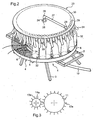
- reference 1 designates the fixed frame of the sampling apparatus in question, constituted by the assembly of metal profiles 2, suitably welded or otherwise interconnected, this frame also including ground support feet 3 for positioning the in any appropriate place.
- the feet 3 are secured to the frame 1 and preferably are articulated on it to facilitate, once the folding of its feet carried out, the movement and transport of the frame from one place to another, depending on the place where the samples are to be made.
- the frame 1 further comprises a horizontal support plate 4, provided at its lower part, above the support feet 3, this plate having a mesh surface 5 or widely perforated for the reasons explained below.
- This tray is provided with an outer edge 6, circular and slightly raised to extend upwards from the mesh surface 5.
- a supply duct 7 which extends vertically perpendicular to the plane of the plate and which is connected by a rotary joint device 8, of the kind gland or the like, to a connection 9, connecting this conduit with the end of a pipe 10 whose other end is immersed in a flow of water (not shown), located near and from which the apparatus makes it possible to take the successive samples desired.
- the pipework 10 is provided with a conventional suction pump (not shown) which makes it possible to take these samples in the flow of water, either at determined time intervals, preferably identical from one to the next. other, depending on the variation of the water level in the flow, especially whenever the water height increases by a determined value.
- the vertical duct 7 for supplying water is integral with a ring 11, extending horizontally inside the frame 1, parallel to the support plate 4, this ring comprising at its periphery a toothing 12 which, in the example illustrated on the Figure 1 , is inclined so as to cooperate with the threaded portion 13 of an endless screw 14, in engagement with it.
- the worm can be substituted by a pinion 14a whose teeth 13a cooperate with a toothing 12 homologous, this straight, provided at the periphery of the drive ring 11, as schematically shown in the detailed view of the Figure 3 .
- the screw 14 journalled in support bearings 15 and 16 fixed on two profiles 2 of the frame 1 and is continuously rotated on itself by means of an asynchronous motor 17 whose power cables 18 are joined together, remotely. device, at a suitable power source.
- the supply duct 7 thus rotates inside the frame 1 while being held axially in the latter by gussets 19 and 20, suitably welded on crosspieces, respectively 21 and 22, of the frame.
- the Figure 1 illustrates in exploded view a distribution disk 23, extending horizontally, the Figure 2 showing the positioning of this disk on the frame 1 once the assembly of the various parts of the device.
- the distribution disk 23 has a circular profile whose diameter is substantially equal to that of the raised edge 6 of the support plate 4 and comprises a central opening 24 through which the upper end 25 of the supply duct 7 protrudes slightly above disk when it is in place.
- This end 25 of the duct 7 is connected by a bent element 26 at one end of a horizontal distributor arm 27 which extends radially above the distribution disk 23, parallel to the latter, this arm having at its opposite end in the conduit, a bucket 28 through which the water taken, discharged into the conduit 7 and beyond this in the arm 27 by the suction pump, is capable of being delivered to flow through the disk 23 by any one of a plurality of distribution passages 29.
- passages 29 are distributed in a circle 30 on the periphery of the disc 23 and are even in number, each of water being disposed at the same distance from the center of the disc, so as to be one by one successively served by the bucket 28 at the end of the distributor arm 27.
- Each passage 29 is also associated with a short pipe element 31, which is connected to it in a sealed manner and extends for a suitable distance below the surface of the distribution disc 23.
- the plate 4 secured to the fixed frame 1 supports on its mesh surface 5, a set of containers 32, the kind bottle or other, preferably plastic, these containers 32 each having an upper filling port 33 whose diameter is such that the end of a pipe element 31 carried by the disc 23 can be freely engaged, so that a sample of water taken from the flow and delivered by the distributor arm 27 through the passage 29 of the disc associated with this element, collects in the container that receives the latter.
- the number of containers 32 arranged on the grid surface 5 of the support plate 4 is equal to half that of the passages 29 provided in the distribution disc 23, the passages associated with two successive containers being separated by a homologous passage whose pipe element 31 is free, the water delivered by this element, when the arm dispenser 27 is located above this passage, spreading on the ground through the meshes of the grid surface 5, outside the containers 32.
- This arrangement has the advantage of allowing the purge of the piping 10, the supply duct 7 and the distributor arm 27 to be purged after each sample taken into a container 32, before the next sample is collected in another container located on the support plate 4 after the previous one.
- the containers 32 thus distributed on the support plate 4 are staggered from one to the other being held outwardly of the plate by the raised edge 6 which extends to the periphery of the latter.
- An analogous edge 34, parallel to the edge 6, can also be provided on the tray, further inside the frame 1 to better maintain the position of all the containers.
- the apparatus may comprise a removable cover (not shown so as not to overload the drawing), this cover being located above the distribution disk 23 and the distributor arm 27 and having a circular return directed downwards to externally surround all the containers 32 placed on the support plate 4.
- the containers containing the collected samples, collected from the dispenser arm can then be easily taken one by one on the support plate in order to proceed, on the corresponding sample, to the measurements provided for in using a separate apparatus which, advantageously, is designed to deliver, in addition to an evaluation of the parameters specific to the sample, such as in particular the quantity of sediments which it comprises or an estimate of its turbidity, other information concerning the velocity and flow rate of the flow from which the samples originated or the instantaneous water depth thereof.
Landscapes
- Life Sciences & Earth Sciences (AREA)
- Hydrology & Water Resources (AREA)
- Physics & Mathematics (AREA)
- Health & Medical Sciences (AREA)
- Chemical & Material Sciences (AREA)
- Analytical Chemistry (AREA)
- Biochemistry (AREA)
- General Health & Medical Sciences (AREA)
- General Physics & Mathematics (AREA)
- Immunology (AREA)
- Pathology (AREA)
- Sampling And Sample Adjustment (AREA)
Claims (8)
- Vorrichtung zur automatischen Entnahme von Wasserproben aus einer kontinuierlichen Strömung, wobei die Vorrichtung ein feststehendes Gestell (1) umfasst, das eine horizontale Platte (4) zum Tragen mehrerer sauberer Behälter (32) umfasst, die dazu geeignet sind, jeweils in ihrer oberen offenen Einfüllöffnung (33) eine bestimmte Wasserprobe aufzunehmen, wobei diese Behälter entsprechend einer kreisförmigen Anordnung auf dieser Platte um eine zentrale vertikale Achse verteilt sind, gemäß der ein Antriebskranz (11) parallel zu der Platte gedreht wird, wobei dieser Kranz fest mit einer Wasserzulaufleitung (7) verbunden ist, die sich senkrecht zu der Platte erstreckt und an einem Ende mittels einer Drehkupplung (8) mit einer Pumpe zum Ansaugen von Wasser aus der Strömung angeschlossen ist und deren anderes Ende (25) mit einem horizontalen Verteilerarm (27) zusammengeführt ist, der sich radial über den auf der Trageplatte angeordneten Behälter erstreckt, wobei dieser Verteilerarm über sein Ende (28), das der Achse gegenüber liegt, nacheinander in jeden dieser Behälter eine Wasserprobe bezüglich der Drehung dieses Arms unter Einwirkung des Antriebskranzes abgibt, dadurch gekennzeichnet, dass die horizontale Trageplatte (4) über den offenen Öffnungen der Behälter eine Verteilungsscheibe (23) umfasst, die parallel zu der Platte ist und eine gerade Anzahl von Verteilungsdurchlässen (29) aufweist, wobei die Anzahl dem Doppelten der Anzahl der Behälter (32) entspricht, wobei die Hälfte dieser Durchlässe jeweils in Bezug auf eine offene Öffnung (33) eines dieser Behälter angeordnet ist und dies Durchlässe paarweise durch einen entsprechenden Zwischendurchlass zum Ablassen getrennt sind, so dass zwischen zwei Proben, die in zwei aufeinander folgenden Behältern aufgefangen wurden, das von dem Verteilerarm (27) abgegebene Wasser durch einen Zwischendurchlauf abgelassen wird, um eine Spülung dieses Arms und der Zulaufleitung (7) nach dem Befüllen eines beliebigen Behälters mit einer Probe und vor dem Befüllen des folgenden Behälters, der Drehung des Arms folgend, durchzuführen.
- Vorrichtung nach Anspruch 1, dadurch gekennzeichnet, dass der Antriebskranz (11) der wasserzulaufleitung (7) eine geneigte Umfangsverzahnung (12) bezüglich einer Verteilersteuerschraube (13) umfasst, die in einer kontinuierlichen Drehung von einem Asynchronelektromotor angetrieben wird.
- Vorrichtung nach Anspruch 1, dadurch gekennzeichnet, dass der Antriebskranz (11) eine aufrecht stehende Umfangsverzahnung (13a) bezüglich eines Zahnrads (14a) umfasst.
- Vorrichtung nach einem der Ansprüche 1 bis 3, dadurch gekennzeichnet, dass jeder der Verteilungsdurchlässe (29), die in der Verteilungsscheibe (23) vorgesehen sind, ein kurzes Schlauchleitungselement (31) umfasst, das dazu geeignet ist, die Wasserprobe zur offenen Einfüllöffnung (33) jedes Behälters (32) zu leiten oder das Ablassen der Spülung der Zulaufleitung (7) und des Verteilerarms (27) zwischen der Befüllung von zwei aufeinander folgenden Behältern sicherzustellen.
- Vorrichtung nach einem der Ansprüche 1 bis 4, dadurch gekennzeichnet, dass die Behälter (32) auf der horizontalen Trageplatte (4) in einer versetzten Verteilung auf dem Umfang dieser Platte unter den Verteilungsdurchlässen (29) auf der Verteilungsscheibe (23) angeordnet sind.
- Vorrichtung nach einem der Ansprüche 1 bis 5, dadurch gekennzeichnet, dass cie horizontale Trageplatte (4) eine erhöhte äußere Kante (6) zur Positionierung und Immobilisierung von unter der Verteilungsscheibe (23) angeordneten Behältern umfasst.
- Vorrichtung nach einem der Ansprüche 1 bis 6, dadurch gekennzeichnet, dass die Trageplatte (4) eine vergitterte oder perforierte Oberfläche (5) umfasst, auf der die Behälter (32) ruhen, um die Strömung von Spülwasser, das von dem Verteilerarm (27) abgegeben wurde, zwischen den Befüllungen von zwei aufeinander folgenden Behältern zu ermöglichen.
- Vorrichtung nach einem der Ansprüche 1 bis 7, dadurch gekennzeichnet, dass das feststehende Gestell (1) mit einer abnehmbaren äußeren Schutzhaube verbunden ist, deren Entfernen freien Zugriff auf die Verteilungsscheibe (23) ermöglicht.
Applications Claiming Priority (2)
| Application Number | Priority Date | Filing Date | Title |
|---|---|---|---|
| FR0601104A FR2897160B1 (fr) | 2006-02-08 | 2006-02-08 | Appareil pour le prelevement automatique d'echantillons dans un ecoulement continu |
| PCT/FR2007/000092 WO2007090941A2 (fr) | 2006-02-08 | 2007-01-18 | Appareil pour le prelevement automatique d'echantillons dans un ecoulement continu |
Publications (2)
| Publication Number | Publication Date |
|---|---|
| EP1982157A2 EP1982157A2 (de) | 2008-10-22 |
| EP1982157B1 true EP1982157B1 (de) | 2011-10-19 |
Family
ID=37057353
Family Applications (1)
| Application Number | Title | Priority Date | Filing Date |
|---|---|---|---|
| EP07730829A Not-in-force EP1982157B1 (de) | 2006-02-08 | 2007-01-18 | Vorrichtung zur automatischen probenentfernung aus einem durchfluss |
Country Status (6)
| Country | Link |
|---|---|
| US (1) | US20090242076A1 (de) |
| EP (1) | EP1982157B1 (de) |
| AP (1) | AP2450A (de) |
| AT (1) | ATE529731T1 (de) |
| FR (1) | FR2897160B1 (de) |
| WO (1) | WO2007090941A2 (de) |
Families Citing this family (9)
| Publication number | Priority date | Publication date | Assignee | Title |
|---|---|---|---|---|
| US8791015B2 (en) * | 2011-04-30 | 2014-07-29 | Stats Chippac, Ltd. | Semiconductor device and method of forming shielding layer over active surface of semiconductor die |
| CN105571901B (zh) * | 2015-12-10 | 2018-02-13 | 浙江省海洋水产研究所 | 一种旋转半隔离式高精度浮游生物取样系统 |
| CN107554702A (zh) * | 2017-09-29 | 2018-01-09 | 北京东方园林环境股份有限公司 | 一种用于水质自动留样的浮标装置及留样方法 |
| CN110006708A (zh) * | 2019-04-28 | 2019-07-12 | 常州机电职业技术学院 | 一种径流水样采集装置 |
| US12163871B2 (en) | 2019-09-02 | 2024-12-10 | Smarta Industrial Pty Ltd | Flushing device for a milk sampler |
| CN113281107B (zh) * | 2021-04-12 | 2023-06-02 | 玉屏侗族自治县环境监测站 | 多参数分析留样器 |
| CN113188843B (zh) * | 2021-05-10 | 2022-09-02 | 江西怡杉环保股份有限公司 | 一种水质采样设备 |
| CN116609127B (zh) * | 2023-04-26 | 2024-05-24 | 宁波市盛甬海洋技术有限公司 | 一种防沉淀的水质取样检测设备及检测方法 |
| CN120629502B (zh) * | 2025-08-13 | 2025-10-10 | 西南科技大学 | 自动化浸出实验装置及放射性废物固化体浸出实验系统 |
Family Cites Families (8)
| Publication number | Priority date | Publication date | Assignee | Title |
|---|---|---|---|---|
| FR2026808A1 (de) * | 1968-12-21 | 1970-09-18 | Olympus Optical Co | |
| GB1386106A (en) * | 1972-11-10 | 1975-03-05 | Sampflo Ltd | Sampling apparatus |
| US3924471A (en) * | 1974-02-07 | 1975-12-09 | Ernst Singer | Automatic liquid sample taking and segregating apparatus |
| DE2415011A1 (de) * | 1974-03-28 | 1975-10-02 | Buehler Fa Edmund | Probenentnahmegeraet zur entnahme von einzelproben |
| US4415011A (en) * | 1981-11-02 | 1983-11-15 | Isco, Inc. | Sample collector |
| GB9118208D0 (en) * | 1991-08-23 | 1991-10-09 | Aquamatic Ltd | Improved automatic wastewater sampler |
| GB2294544B (en) * | 1994-10-25 | 1997-11-26 | Aquamatic Ltd | Sample collector |
| AU2005216828B2 (en) * | 2004-02-27 | 2009-03-12 | Stibbe Management Bv | Paint and hair dye dispensers |
-
2006
- 2006-02-08 FR FR0601104A patent/FR2897160B1/fr not_active Expired - Fee Related
-
2007
- 2007-01-18 AP AP2008004551A patent/AP2450A/xx active
- 2007-01-18 AT AT07730829T patent/ATE529731T1/de not_active IP Right Cessation
- 2007-01-18 US US12/278,399 patent/US20090242076A1/en not_active Abandoned
- 2007-01-18 WO PCT/FR2007/000092 patent/WO2007090941A2/fr not_active Ceased
- 2007-01-18 EP EP07730829A patent/EP1982157B1/de not_active Not-in-force
Also Published As
| Publication number | Publication date |
|---|---|
| AP2008004551A0 (en) | 2008-08-31 |
| WO2007090941A2 (fr) | 2007-08-16 |
| FR2897160A1 (fr) | 2007-08-10 |
| ATE529731T1 (de) | 2011-11-15 |
| AP2450A (en) | 2012-08-31 |
| US20090242076A1 (en) | 2009-10-01 |
| WO2007090941A3 (fr) | 2007-09-27 |
| EP1982157A2 (de) | 2008-10-22 |
| FR2897160B1 (fr) | 2008-04-18 |
Similar Documents
| Publication | Publication Date | Title |
|---|---|---|
| WO2007090941A2 (fr) | Appareil pour le prelevement automatique d'echantillons dans un ecoulement continu | |
| EP3365514A1 (de) | Schwimmbeckenreiniger mit hindernisbeseitigungsvorrichtung | |
| EP2334875B1 (de) | Spülvorrichtung, insbesondere für ein toilettenbecken, und sich ergebende toilettenbecken- und spülvorrichtungsanordnung | |
| WO2012110427A1 (fr) | Fouet pour appareil electromenager de preparation culinaire | |
| EP3140542B1 (de) | Vorrichtung zur überwachung des betriebs eines dosisspenders eines flüssigen additivs in eine hauptflüssigkeit und mit solch einer vorrichtung ausgestatteter dosisspender | |
| FR2989596A1 (fr) | Appareil nettoyeur de surface immergee a filtration centripete | |
| EP0462912A1 (de) | Schüttguthebevorrichtung | |
| WO2000043304A1 (fr) | Dispositif de dispersion d'un materiau solide divise a l'interieur d'un recipient | |
| FR3019722A1 (fr) | Dispositif de vidange pour un appareil de cuisson | |
| FR2463062A1 (fr) | Dispositif mecanique pour le conditionnement, dans des recipients, de liquides ou de poudres en quantite dosee | |
| EP2588241B1 (de) | Vorrichtung zum versprühen eines tröpchennebels | |
| EP2047228B1 (de) | Vorrichtung zur enthahme von oberflächenproben aus einem flusslauf in einer hochwasser zeit | |
| FR2639686A1 (fr) | Pompe peristaltique a rotor muni de galets cooperant avec un tuyau de pompe s'appuyant sur un chemin courbe de guidage | |
| EP3690168A1 (de) | Filterblock für schwimmbad, der mit einem messsystem des verstopfungsgrads und/oder verstopfungszustands eines filters ausgestattet ist | |
| EP0475867B1 (de) | Wäscher-Tür für Massagevorrichtung | |
| FR3040772A1 (fr) | Distributeur de glacons. | |
| FR2565508A1 (fr) | Machine a peindre sous-marine comportant un dispositif d'application de la peinture a mouvement pulsatoire associe a un dispositif rotatif de lissage | |
| FR2574150A1 (fr) | Dispositif de couplage automatique de tuyaux | |
| EP3581863A1 (de) | Verbesserter eiswürfelspender | |
| CA1303843C (fr) | Machine a peindre sous-marine comportant un dispositif d'application de la peinture a mouvement pulsatoire associe a un dispositif rotatif de lissage | |
| EP0128847B1 (de) | Mechanismus zum Umkehren von Bewegungen und seine Anwendung für Dränagevorrichtungen für Spülbecken | |
| FR2737081A1 (fr) | Refroidisseur de lait a couvercle et agitateur | |
| FR2519231A1 (fr) | Appareil de desilage | |
| CA1177023A (fr) | Appareil distributeur automatique de boissons | |
| CA1316792C (fr) | Dispositif de couplage automatique de tuyaux |
Legal Events
| Date | Code | Title | Description |
|---|---|---|---|
| PUAI | Public reference made under article 153(3) epc to a published international application that has entered the european phase |
Free format text: ORIGINAL CODE: 0009012 |
|
| 17P | Request for examination filed |
Effective date: 20080701 |
|
| AK | Designated contracting states |
Kind code of ref document: A2 Designated state(s): AT BE BG CH CY CZ DE DK EE ES FI FR GB GR HU IE IS IT LI LT LU LV MC NL PL PT RO SE SI SK TR |
|
| DAX | Request for extension of the european patent (deleted) | ||
| GRAP | Despatch of communication of intention to grant a patent |
Free format text: ORIGINAL CODE: EPIDOSNIGR1 |
|
| GRAS | Grant fee paid |
Free format text: ORIGINAL CODE: EPIDOSNIGR3 |
|
| GRAA | (expected) grant |
Free format text: ORIGINAL CODE: 0009210 |
|
| AK | Designated contracting states |
Kind code of ref document: B1 Designated state(s): AT BE BG CH CY CZ DE DK EE ES FI FR GB GR HU IE IS IT LI LT LU LV MC NL PL PT RO SE SI SK TR |
|
| REG | Reference to a national code |
Ref country code: GB Ref legal event code: FG4D Free format text: NOT ENGLISH |
|
| REG | Reference to a national code |
Ref country code: CH Ref legal event code: NV Representative=s name: ABREMA AGENCE BREVET ET MARQUES, GANGUILLET Ref country code: CH Ref legal event code: EP |
|
| REG | Reference to a national code |
Ref country code: IE Ref legal event code: FG4D |
|
| REG | Reference to a national code |
Ref country code: DE Ref legal event code: R096 Ref document number: 602007018043 Country of ref document: DE Effective date: 20120126 |
|
| REG | Reference to a national code |
Ref country code: NL Ref legal event code: VDEP Effective date: 20111019 |
|
| LTIE | Lt: invalidation of european patent or patent extension |
Effective date: 20111019 |
|
| REG | Reference to a national code |
Ref country code: AT Ref legal event code: MK05 Ref document number: 529731 Country of ref document: AT Kind code of ref document: T Effective date: 20111019 |
|
| PG25 | Lapsed in a contracting state [announced via postgrant information from national office to epo] |
Ref country code: LT Free format text: LAPSE BECAUSE OF FAILURE TO SUBMIT A TRANSLATION OF THE DESCRIPTION OR TO PAY THE FEE WITHIN THE PRESCRIBED TIME-LIMIT Effective date: 20111019 Ref country code: IS Free format text: LAPSE BECAUSE OF FAILURE TO SUBMIT A TRANSLATION OF THE DESCRIPTION OR TO PAY THE FEE WITHIN THE PRESCRIBED TIME-LIMIT Effective date: 20120219 |
|
| REG | Reference to a national code |
Ref country code: IE Ref legal event code: FD4D |
|
| PG25 | Lapsed in a contracting state [announced via postgrant information from national office to epo] |
Ref country code: SE Free format text: LAPSE BECAUSE OF FAILURE TO SUBMIT A TRANSLATION OF THE DESCRIPTION OR TO PAY THE FEE WITHIN THE PRESCRIBED TIME-LIMIT Effective date: 20111019 Ref country code: LV Free format text: LAPSE BECAUSE OF FAILURE TO SUBMIT A TRANSLATION OF THE DESCRIPTION OR TO PAY THE FEE WITHIN THE PRESCRIBED TIME-LIMIT Effective date: 20111019 Ref country code: PT Free format text: LAPSE BECAUSE OF FAILURE TO SUBMIT A TRANSLATION OF THE DESCRIPTION OR TO PAY THE FEE WITHIN THE PRESCRIBED TIME-LIMIT Effective date: 20120220 Ref country code: NL Free format text: LAPSE BECAUSE OF FAILURE TO SUBMIT A TRANSLATION OF THE DESCRIPTION OR TO PAY THE FEE WITHIN THE PRESCRIBED TIME-LIMIT Effective date: 20111019 Ref country code: SI Free format text: LAPSE BECAUSE OF FAILURE TO SUBMIT A TRANSLATION OF THE DESCRIPTION OR TO PAY THE FEE WITHIN THE PRESCRIBED TIME-LIMIT Effective date: 20111019 Ref country code: GR Free format text: LAPSE BECAUSE OF FAILURE TO SUBMIT A TRANSLATION OF THE DESCRIPTION OR TO PAY THE FEE WITHIN THE PRESCRIBED TIME-LIMIT Effective date: 20120120 |
|
| PG25 | Lapsed in a contracting state [announced via postgrant information from national office to epo] |
Ref country code: CY Free format text: LAPSE BECAUSE OF FAILURE TO SUBMIT A TRANSLATION OF THE DESCRIPTION OR TO PAY THE FEE WITHIN THE PRESCRIBED TIME-LIMIT Effective date: 20111019 |
|
| BERE | Be: lapsed |
Owner name: INSTITUT DE RECHERCHE POUR LE DEVELOPPEMENT ( IRD) Effective date: 20120131 |
|
| PG25 | Lapsed in a contracting state [announced via postgrant information from national office to epo] |
Ref country code: SK Free format text: LAPSE BECAUSE OF FAILURE TO SUBMIT A TRANSLATION OF THE DESCRIPTION OR TO PAY THE FEE WITHIN THE PRESCRIBED TIME-LIMIT Effective date: 20111019 Ref country code: DK Free format text: LAPSE BECAUSE OF FAILURE TO SUBMIT A TRANSLATION OF THE DESCRIPTION OR TO PAY THE FEE WITHIN THE PRESCRIBED TIME-LIMIT Effective date: 20111019 Ref country code: BG Free format text: LAPSE BECAUSE OF FAILURE TO SUBMIT A TRANSLATION OF THE DESCRIPTION OR TO PAY THE FEE WITHIN THE PRESCRIBED TIME-LIMIT Effective date: 20120119 Ref country code: IE Free format text: LAPSE BECAUSE OF FAILURE TO SUBMIT A TRANSLATION OF THE DESCRIPTION OR TO PAY THE FEE WITHIN THE PRESCRIBED TIME-LIMIT Effective date: 20111019 Ref country code: CZ Free format text: LAPSE BECAUSE OF FAILURE TO SUBMIT A TRANSLATION OF THE DESCRIPTION OR TO PAY THE FEE WITHIN THE PRESCRIBED TIME-LIMIT Effective date: 20111019 Ref country code: EE Free format text: LAPSE BECAUSE OF FAILURE TO SUBMIT A TRANSLATION OF THE DESCRIPTION OR TO PAY THE FEE WITHIN THE PRESCRIBED TIME-LIMIT Effective date: 20111019 |
|
| PLBE | No opposition filed within time limit |
Free format text: ORIGINAL CODE: 0009261 |
|
| STAA | Information on the status of an ep patent application or granted ep patent |
Free format text: STATUS: NO OPPOSITION FILED WITHIN TIME LIMIT |
|
| PG25 | Lapsed in a contracting state [announced via postgrant information from national office to epo] |
Ref country code: PL Free format text: LAPSE BECAUSE OF FAILURE TO SUBMIT A TRANSLATION OF THE DESCRIPTION OR TO PAY THE FEE WITHIN THE PRESCRIBED TIME-LIMIT Effective date: 20111019 Ref country code: RO Free format text: LAPSE BECAUSE OF FAILURE TO SUBMIT A TRANSLATION OF THE DESCRIPTION OR TO PAY THE FEE WITHIN THE PRESCRIBED TIME-LIMIT Effective date: 20111019 Ref country code: IT Free format text: LAPSE BECAUSE OF FAILURE TO SUBMIT A TRANSLATION OF THE DESCRIPTION OR TO PAY THE FEE WITHIN THE PRESCRIBED TIME-LIMIT Effective date: 20111019 Ref country code: MC Free format text: LAPSE BECAUSE OF NON-PAYMENT OF DUE FEES Effective date: 20120131 |
|
| 26N | No opposition filed |
Effective date: 20120720 |
|
| GBPC | Gb: european patent ceased through non-payment of renewal fee |
Effective date: 20120119 |
|
| PG25 | Lapsed in a contracting state [announced via postgrant information from national office to epo] |
Ref country code: GB Free format text: LAPSE BECAUSE OF NON-PAYMENT OF DUE FEES Effective date: 20120119 |
|
| REG | Reference to a national code |
Ref country code: DE Ref legal event code: R097 Ref document number: 602007018043 Country of ref document: DE Effective date: 20120720 |
|
| PG25 | Lapsed in a contracting state [announced via postgrant information from national office to epo] |
Ref country code: BE Free format text: LAPSE BECAUSE OF NON-PAYMENT OF DUE FEES Effective date: 20120131 |
|
| PG25 | Lapsed in a contracting state [announced via postgrant information from national office to epo] |
Ref country code: AT Free format text: LAPSE BECAUSE OF FAILURE TO SUBMIT A TRANSLATION OF THE DESCRIPTION OR TO PAY THE FEE WITHIN THE PRESCRIBED TIME-LIMIT Effective date: 20111019 |
|
| PG25 | Lapsed in a contracting state [announced via postgrant information from national office to epo] |
Ref country code: ES Free format text: LAPSE BECAUSE OF FAILURE TO SUBMIT A TRANSLATION OF THE DESCRIPTION OR TO PAY THE FEE WITHIN THE PRESCRIBED TIME-LIMIT Effective date: 20120130 |
|
| PG25 | Lapsed in a contracting state [announced via postgrant information from national office to epo] |
Ref country code: FI Free format text: LAPSE BECAUSE OF FAILURE TO SUBMIT A TRANSLATION OF THE DESCRIPTION OR TO PAY THE FEE WITHIN THE PRESCRIBED TIME-LIMIT Effective date: 20111019 |
|
| PG25 | Lapsed in a contracting state [announced via postgrant information from national office to epo] |
Ref country code: TR Free format text: LAPSE BECAUSE OF FAILURE TO SUBMIT A TRANSLATION OF THE DESCRIPTION OR TO PAY THE FEE WITHIN THE PRESCRIBED TIME-LIMIT Effective date: 20111019 |
|
| PG25 | Lapsed in a contracting state [announced via postgrant information from national office to epo] |
Ref country code: LU Free format text: LAPSE BECAUSE OF NON-PAYMENT OF DUE FEES Effective date: 20120118 |
|
| PG25 | Lapsed in a contracting state [announced via postgrant information from national office to epo] |
Ref country code: HU Free format text: LAPSE BECAUSE OF FAILURE TO SUBMIT A TRANSLATION OF THE DESCRIPTION OR TO PAY THE FEE WITHIN THE PRESCRIBED TIME-LIMIT Effective date: 20070118 |
|
| REG | Reference to a national code |
Ref country code: FR Ref legal event code: PLFP Year of fee payment: 9 |
|
| PGFP | Annual fee paid to national office [announced via postgrant information from national office to epo] |
Ref country code: DE Payment date: 20150119 Year of fee payment: 9 Ref country code: CH Payment date: 20150202 Year of fee payment: 9 |
|
| PGFP | Annual fee paid to national office [announced via postgrant information from national office to epo] |
Ref country code: FR Payment date: 20150128 Year of fee payment: 9 |
|
| REG | Reference to a national code |
Ref country code: DE Ref legal event code: R119 Ref document number: 602007018043 Country of ref document: DE |
|
| REG | Reference to a national code |
Ref country code: CH Ref legal event code: PL |
|
| REG | Reference to a national code |
Ref country code: FR Ref legal event code: ST Effective date: 20160930 |
|
| PG25 | Lapsed in a contracting state [announced via postgrant information from national office to epo] |
Ref country code: DE Free format text: LAPSE BECAUSE OF NON-PAYMENT OF DUE FEES Effective date: 20160802 Ref country code: LI Free format text: LAPSE BECAUSE OF NON-PAYMENT OF DUE FEES Effective date: 20160131 Ref country code: CH Free format text: LAPSE BECAUSE OF NON-PAYMENT OF DUE FEES Effective date: 20160131 |
|
| PG25 | Lapsed in a contracting state [announced via postgrant information from national office to epo] |
Ref country code: FR Free format text: LAPSE BECAUSE OF NON-PAYMENT OF DUE FEES Effective date: 20160201 |