EP2047228B1 - Vorrichtung zur enthahme von oberflächenproben aus einem flusslauf in einer hochwasser zeit - Google Patents
Vorrichtung zur enthahme von oberflächenproben aus einem flusslauf in einer hochwasser zeit Download PDFInfo
- Publication number
- EP2047228B1 EP2047228B1 EP07858409A EP07858409A EP2047228B1 EP 2047228 B1 EP2047228 B1 EP 2047228B1 EP 07858409 A EP07858409 A EP 07858409A EP 07858409 A EP07858409 A EP 07858409A EP 2047228 B1 EP2047228 B1 EP 2047228B1
- Authority
- EP
- European Patent Office
- Prior art keywords
- tube
- cap
- tubes
- water
- slots
- Prior art date
- Legal status (The legal status is an assumption and is not a legal conclusion. Google has not performed a legal analysis and makes no representation as to the accuracy of the status listed.)
- Not-in-force
Links
Images


Classifications
-
- G—PHYSICS
- G01—MEASURING; TESTING
- G01N—INVESTIGATING OR ANALYSING MATERIALS BY DETERMINING THEIR CHEMICAL OR PHYSICAL PROPERTIES
- G01N1/00—Sampling; Preparing specimens for investigation
- G01N1/02—Devices for withdrawing samples
- G01N1/10—Devices for withdrawing samples in the liquid or fluent state
- G01N1/16—Devices for withdrawing samples in the liquid or fluent state with provision for intake at several levels
-
- G—PHYSICS
- G01—MEASURING; TESTING
- G01N—INVESTIGATING OR ANALYSING MATERIALS BY DETERMINING THEIR CHEMICAL OR PHYSICAL PROPERTIES
- G01N1/00—Sampling; Preparing specimens for investigation
- G01N1/02—Devices for withdrawing samples
- G01N1/10—Devices for withdrawing samples in the liquid or fluent state
- G01N1/20—Devices for withdrawing samples in the liquid or fluent state for flowing or falling materials
- G01N1/2035—Devices for withdrawing samples in the liquid or fluent state for flowing or falling materials by deviating part of a fluid stream, e.g. by drawing-off or tapping
Definitions
- the present invention relates to a device for collecting water samples from the surface of a creek or a similar watercourse, especially during periods of high water when the water level can vary significantly. in a possible short time.
- the present invention thus relates to a device for collecting surface water samples and to record the instant and the height of the collection in a river during floods, which meets these requirements, at the same time. using a robust and inexpensive set, simple to manufacture and easy to operate.
- the device carried by a supporting framework adapted to be implanted in the bed of the stream to be treated is characterized in that it comprises firstly a set of parallel tubes, vertical axes, regularly spaced apart and adapted to each collect a sample of water at the surface, each tube having a height different from one tube to the next on the frame; being closed off at its lower part and having at its upper part slots for the admission of the surface water sample into the tube when the level of the watercourse reaches these slots, and secondly electrical detection means the level of water when the tube is filled, and finally a common control unit, separated from the frame, connected to all the tubes for sequentially measure the moment of their respective filling as the level in the stream increases.
- each tube is cylindrical, is closed at its bottom by a first closure cap covering the end of the tube, and is provided at its upper part with a second cap having the inlet slots of the water in the tube.
- the second cap mounted at the upper end of each tube, has four slots, two by two opposite.
- the second cap comprises a pipe element which passes through its upper bottom for venting at atmospheric pressure from the inside of the tube in order to allow its regular filling by the surface water through the slots intake.
- the second cap has externally a resilient tubular covering member adapted to minimize the exchanges between the outer surface water in the stream and the sample taken from the tube after filling the tube. ci through the slots.
- a cylindrical sleeve is also arranged around each tube between its two caps to allow a positioning always identical to itself of the latter on the tube in order to obtain a perfect reproducibility of the measurements made on this tube, to each of his successive fillings.
- the cylindrical sleeve is arranged to define with the inlet slits of the water in the tube a baffled path, able to avoid a turbulent filling of the tube.
- the cylindrical sleeve is made of a flexible material and is provided with a through notch inclined on the axis of the tube, adapted to ensure its positioning by sliding on the outer surface of this tube between the two caps, the sleeve abutting on the upper edge of the first cap mounted at the bottom of the tube and serving as a support by its edge opposite the second cap, the upper part of the tube.
- the electrical means for detecting the water level when each tube is filled are housed in the second cap at the upper part of the tube and consist of two identical electrodes mounted at the end of two connecting cables with the external control unit, the measurement being carried out by checking the value of the impedance between these two electrodes, the length of the cables inside the second cap corresponding to the height of the filling level of the tube.
- one of the two cables is connected to ground and the other to the external control assembly.
- the two cables are parallel, embedded and immobilized in position in the second cap at the top of the tube, by a block of resin or a similar hardenable material, cast inside this cap.
- the support frame of the tubes comprises a frame comprising a horizontal base common to the different parallel tubes with vertical axes which rest on a bearing surface of this base at their lower end and an inclined spacer of immobilization of these tubes according to their height, respectively variable from one tube to the next.
- connection between the tubes and the immobilization spacer is effected by means of the second cap of each tube, mounted at the upper part thereof.
- the implantation of the framework in the bed of the watercourse is carried out by means of a vertical anchoring foot, able to be driven into the ground at the chosen location.
- the inclination of the spacer relative to the base is adjustable around transverse connecting pins mounted in variable locations provided in the base and in a vertical upright, perpendicular thereto, depending on the respective height of the tubes.
- control assembly comprises a waterproof connection connector with the cables connected to the measurement electrodes of each tube.
- This control assembly advantageously comprises means for recording data relating to the sampling of water carried out in each tube, in particular the time, the identification of the tube and the level reached.
- FIG. 1 and 2 a part of a stream or stream 1 on which partial measurements are made during flood periods by means of sampling of surface water is schematically represented in a partial section performed with a device 2 according to the invention.
- This device 2 consists in particular of a rigid frame 3, consisting essentially of a horizontal base 4 and a vertical upright 5.
- the base 4 is intended to be applied against the floor 6 of the bed of the stream 1, the vertical upright 5 having a vertical anchoring foot 7 which can be depressed sufficiently deep in the ground 6 to adequately immobilize the bed. backbone.
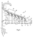
- the anchor foot 7 has at its lower end a tapered tip 8 (see FIG. Figure 3 which also illustrates this, in folded view), allowing a good penetration of the foot into the ground and consequently a satisfactory maintenance of the frame 3 without the flow of the stream 1 may cause a change in the positioning the sampling device which would distort the measurements made.
- the frame 3 serves to support a plurality of parallel sampling tubes 9, with vertical axes, preferably regularly spaced, intended to collect each a sample of water on the surface of the stream 1 as and when the level in the latter increases during the flood period, each tube 9 having a height different from one tube to the next, these tubes being distributed along the length of the base 4 over a range of which these tubes rest at their lower part.
- sampling tubes 9 are held in place by a spacer 10 which ensures their immobilization vis-à-vis the frame, this spacer can take an appropriate inclination which varies with the respective height dimensions of the various tubes, thanks to appropriately distributed holes, such as 11, 12 and 13, provided on the base 4, the vertical upright 5 and the spacer 10, and adapted to cooperate with transverse pins provided with locking nuts 14 ( Figure 3 ).
- FIG. 3 to 5 illustrate in more detail the particular structure of the different sampling tubes 9 and the frame 3 which supports them.
- Each tube 9, cylindrical, open at its two ends, respectively 15 and 16 is made by means of a suitable material, preferably a transparent plastic material, in particular of the PVC type or the like.
- each tube 9 is closed by a first waterproof cap 17, also of PVC, and which has a flat bottom 18 for closely applying the tube against the flat surface provided for this purpose on the base 4 of the backbone.
- the same tube 9 is provided with a second cap 19, also sealed, opposite to the first cap 17 and which thus caps the upper end of the tube, this second cap having lateral slots 20 ( Figure 5 ), preferably four in the example more especially considered, two by two diametrically opposed, these slots allowing the water flowing in particular to the surface of the stream 1, to penetrate gradually and without turbulence in this tube, according to a chicane path shown schematically by the arrow 21 ( Figure 4 ) inside the tube 9, by filling it as the level of the watercourse increases.
- the upper cap 19 externally comprises a resilient tubular covering member 19a, adapted to minimize the exchanges between the external water in the stream 1 and the sample taken from the tube 9 after filling thereof. through the slots 20.
- the space between the two caps 17 and 19 on the outer surface of the tube 9 is further defined by an outer sleeve 22 forming a positioning wedge, ensuring the abutment of the two caps on its ends, this sleeve 22 having in particular the purpose of allow a spacing of these caps always equal to itself for a good reproducibility of the water level detection measures in the tube as explained later, especially at each reuse of the tube for a new sample.
- the sleeve 22 preferably comprises a through notch 23, inclined on the vertical direction, which facilitates the sliding of this sleeve on the outer surface of the tube 9 during its introduction.
- the latter In its bottom 24, which delimits its upper part above the end of the tube 9 capped by the cap 19, the latter comprises a bore 25, through which can freely engage a pipe element 26 whose open end is located above the tube, this element allowing venting at the external atmospheric pressure of the inside of the tube, so as to allow its free filling with water through the slots 20.
- Additional holes are provided laterally in the cap 19 to allow its attachment to the spacer 10 of the frame 3.
- the various piping elements 26 thus venting the inside of the various tubes 9 carried by the frame 3, are connected to a holding sleeve 27, common to these elements, immobilized against the vertical upright 5 above the spacer 10.
- Each upper cap 19 of any tube 9 also comprises, in its bottom 24, on either side of the central bore 25, two holes, respectively 28 and 29, for the passage of two electrical cables 30 and 31 which penetrate to the inside of the cap above the tube 9, the length of these cables inside the second cap 19 corresponding to the height of the filling level of the tube 9.
- These cables 30 and 31 are provided at their lower ends in the electrode cap, respectively 32 and 33, .disposées at the same horizontal level substantially to the upper part of the tube 9, these electrodes and these cables being immobilized in the cap 19 by a block of resin or similar material 34, cast and cured inside the cap.
- the various cables 30 and 31 coming from the various sampling tubes 9 positioned on the framework 3 are joined to a common connector 35, mounted in a sealed housing 36, advantageously fixed on the top of the inclined spacer 10.
- the equipment of the apparatus comprises an external control assembly (not shown), comprising electronic means adapted to sequentially measure the instant of filling of each of the tubes and the respective level reached by the water in them at As the height of the stream 1 increases, preferably one of the two cables 30 is grounded and the other 31 is connected to the external control assembly.
- the electrodes 32 and 33 immobilized in the cap 19 by the resin block 34 form the electrical detection means of the water level, in particular by acting as the two electrodes of a capacitor whose dielectric is constituted by air having a high impedance as long as the water does not reach these electrodes inside the tube concerned, and by the water itself, with a low impedance, when the level of these electrodes is reached by it, at the end of filling the tube through the intake slots 20 upper cap 19.
- the control assembly makes it possible to detect and record this impedance variation and consequently to measure the instant and the level of filling from one tube to the next on the frame with the desired accuracy.
- each tube can be easily separated and extracted from the stream. framework to allow a separate measurement of the quantity and nature of the suspended matter in this tube, that is to say on the water taken from the surface of the watercourse.
- an autonomous sampling device simple and inexpensive, allowing excellent reproducibility of the measurements made, the samples taken at a specific point of the watercourse ensuring measurements perfectly representative of the dynamics of it and its behavior during floods.
- the external control assembly whose characteristics are in principle conventional and do not matter to the invention, can be achieved in any form suitable for implementing the protocols adapted to the measurements to be made in each case.
- these measurements can easily be processed by a computer program adapted to characterize the watercourse, in particular its variations in height, suspended solids and dissolved loads.
Landscapes
- Life Sciences & Earth Sciences (AREA)
- Hydrology & Water Resources (AREA)
- Physics & Mathematics (AREA)
- Health & Medical Sciences (AREA)
- Chemical & Material Sciences (AREA)
- Analytical Chemistry (AREA)
- Biochemistry (AREA)
- General Health & Medical Sciences (AREA)
- General Physics & Mathematics (AREA)
- Immunology (AREA)
- Pathology (AREA)
- Sampling And Sample Adjustment (AREA)
- Testing Resistance To Weather, Investigating Materials By Mechanical Methods (AREA)
Claims (17)
- Vorrichtung zur Entnahme von Proben an der Oberfläche eines Wasserlaufes (1) zu Zeiten von Hochwasser, die von einem Traggestell (3) getragen wird, das in das Bett des Wasserlaufes gestellt werden kann, dadurch gekennzeichnet, dass sie einerseits eine Gesamtheit von parallelen Rohren (9) mit vertikalen Achsen umfasst, die in regelmäßigen Abständen angeordnet sind und jeweils eine Wasserprobe an der Oberfläche aufnehmen können, wobei jedes Rohr eine unterschiedliche Höhe von einem Rohr zum nächsten auf dem Gestell aufweist, an seinem unteren Teil verschlossen ist und an seinem oberen Teil Einlassschlitze (20) für die Oberflächenwasserprobe in das Rohr, wenn das Niveau des Wasserlaufes diese Schlitze erreicht, aufweist, und andererseits elektrische Mittel (32, 33) zur Erfassung des Wasserniveaus, wenn das Rohr (9) gefüllt ist, und schließlich eine gemeinsame Steuereinheit, die von dem Gestell getrennt und mit der Gesamtheit der Rohre verbunden ist, umfasst, um sequentiell den Moment ihrer jeweiligen Befüllung im Zuge des Niveauanstiegs im Wasserlauf zu messen.
- Vorrichtung nach Anspruch 1, dadurch gekennzeichnet, dass jedes Rohr (9) zylindrisch, an seinem unteren Teil durch einen ersten Verschlussstöpsel (17), der sich an das Ende des Rohrs anpasst, verschlossen und an seinem oberen Teil mit einem zweiten Stöpsel (19) versehen ist, der die Einlassschlitze (20) für das Oberflächenwasser in das Rohr umfasst.
- Vorrichtung nach Anspruch 2, dadurch gekennzeichnet, dass der zweite Stöpsel (19), der am oberen Ende jedes Rohrs (9) montiert ist, vier Schlitze (20) umfasst, die einander zwei und zwei gegenüber liegen.
- Vorrichtung nach einem der Ansprüche 2 oder 3, dadurch gekennzeichnet, dass der zweite Stöpsel (19) ein Rohrelement (26) umfasst, das seinen oberen Boden (24) quert, um das Innere des Rohrs bei Luftdruck zu entlüften, um seine regelmäßige Befüllung mit dem Oberflächenwasser durch die Einlassschlitze (20) zu ermöglichen.
- Vorrichtung nach einem der Ansprüche 2 bis 4, dadurch gekennzeichnet, dass der zweite Stöpsel (19) außen ein elastisches röhrenförmiges Abdeckelement (19a) umfasst, das den Austausch zwischen dem Außenwasser im Wasserlauf (1) und der entnommenen Probe im Rohr (9) nach Befüllung desselben durch die Schlitze (20) minimieren kann.
- Vorrichtung nach einem der Ansprüche 2 bis 5, dadurch gekennzeichnet, dass eine zylindrische Hülle (22) um jedes Rohr (9) zwischen seinen beiden Stöpseln (17, 19) angeordnet ist, um eine immer zu diesem selbst identische Positionierung dieser letztgenannten auf dem Rohr zu ermöglichen.
- Vorrichtung nach Anspruch 6, dadurch gekennzeichnet, dass die zylindrische Hülle (22) derart angeordnet ist, dass sie mit den Einlassschlitzen (20) für das Wasser in das Rohr (9) eine Bahn mit Hindernissen definiert, die eine wirbelnde Befüllung des Rohrs verhindern kann.
- Vorrichtung nach einem der Ansprüche 6 oder 7, dadurch gekennzeichnet, dass die zylindrische Hülle (22) aus einem biegsamen Material hergestellt und mit einer durchgehenden Kerbe (23) versehen ist, die auf die Achse des Rohrs (9) geneigt ist und seine Positionierung durch Gleiten auf der Außenfläche dieses Rohrs zwischen den beiden Stöpseln (17, 19) sicherstellen kann, wobei die Hülle am oberen Rand des ersten Stöpsels, der am unteren Teil des Rohrs montiert ist und mit seinem gegenüber liegenden Rand als Stütze für den zweiten Stöpsel am oberen Teil des Rohrs dient, anschlägt.
- Vorrichtung nach einem der Ansprüche 2 bis 8, dadurch gekennzeichnet, dass die elektrischen Mittel (32, 33) zur Erfassung des Wasserniveaus, wenn jedes Rohrs (9) befüllt ist, in dem zweiten Stöpsel (19) am oberen Rand des Rohrs angeordnet und von zwei identischen Elektroden gebildet sind, die am Ende von zwei Verbindungskabeln (30, 31) mit der äußeren Steuereinheit montiert sind, wobei die Messung durch Kontrolle des Impedanzwertes zwischen diesen beiden Elektroden erfolgt, wobei die Länge der Kabel im Inneren des zweiten Stöpsels der Höhe des Füllstandes des Rohrs entspricht.
- Vorrichtung nach Anspruch 9, dadurch gekennzeichnet, dass eines der beiden Kabel (31) mit der Masse und das andere (30) mit der äußeren Steuereinheit verbunden ist.
- Vorrichtung nach einem der Ansprüche 9 oder 10, dadurch gekennzeichnet, dass die beiden Kabel (30, 31) parallel und versenkt und in dem zweiten Stöpsel (19) am oberen Teil des Rohrs (9) durch einen Block (34) aus Harz oder einem ähnlichen härtbaren Material, das in das Innere dieses Stöpsels gegossen wird, festgestellt sind.
- Vorrichtung nach einem der Ansprüche 1 bis 11, dadurch gekennzeichnet, dass das Stützgestell (3) der Rohre (9) ein Gehäuse besitzt, umfassend eine horizontale Grundfläche (4), die den verschiedenen parallelen Rohren (9) mit vertikalen Achsen, die sich auf diese Grundfläche mit ihrem unteren Ende aufstützen, gemeinsam ist, und eine geneigte Querstrebe (10) zur Feststellung dieser Rohre entlang ihrer Höhe, die von einem Rohr zum nächsten jeweils variiert.
- Vorrichtung nach den Ansprüchen 2 und 12, dadurch gekennzeichnet, dass die Verbindung zwischen den Rohren (9) und der Querstrebe (10) zur Feststellung mit Hilfe des zweiten Stöpsels (19) jedes Rohrs, der am oberen Teil desselben montiert ist, erfolgt.
- Vorrichtung nach einem der Ansprüche 1 bis 13, dadurch gekennzeichnet, dass die Anbringung des Gestells (3) im Bett des Wasserlaufes (1) mit Hilfe eines vertikalen Verankerungsfußes (7) erfolgt, der an der ausgewählten Stelle im Boden (6) versenkt werden kann.
- Vorrichtung nach einem der Ansprüche 12 bis 14, dadurch gekennzeichnet, dass die Neigung der Querstrebe (10) in Bezug zur Grundfläche (4) um Querverbindungsstifte (14) einstellbar ist, die an variablen Stellen, die in der Grundfläche und in einem vertikalen Ständer (5), der zu dieser senkrecht ist, in Abhängigkeit von der jeweiligen Höhe der Rohre (9) montiert sind.
- Vorrichtung nach einem der Ansprüche 9 bis 15, dadurch gekennzeichnet, dass die Steuereinheit einen dichten Verbindungsstecker (35) mit den Kabeln (30, 31) umfasst, die an die Messelektroden (32, 33) jedes Rohrs (9) angeschlossen sind.
- Vorrichtung nach einem der Ansprüche 1 bis 16, dadurch gekennzeichnet, dass die Steuereinheit Mittel zur Aufzeichnung der Daten zu der in jedem Rohr (9) vorgenommenen Wasserentnahme, insbesondere Uhrzeit, Identifikation des Rohrs und erreichter Füllstand, umfasst.
Applications Claiming Priority (2)
| Application Number | Priority Date | Filing Date | Title |
|---|---|---|---|
| FR0608841A FR2906888B1 (fr) | 2006-10-09 | 2006-10-09 | Dispositif pour le prelevement d'echantillons en surface dans un cours d'eau en periode de crue |
| PCT/FR2007/001640 WO2008043908A1 (fr) | 2006-10-09 | 2007-10-09 | Dispositif pour le prelevement d'echantillons en surface dans un cours d'eau en periode de crue |
Publications (2)
| Publication Number | Publication Date |
|---|---|
| EP2047228A1 EP2047228A1 (de) | 2009-04-15 |
| EP2047228B1 true EP2047228B1 (de) | 2010-07-21 |
Family
ID=37649447
Family Applications (1)
| Application Number | Title | Priority Date | Filing Date |
|---|---|---|---|
| EP07858409A Not-in-force EP2047228B1 (de) | 2006-10-09 | 2007-10-09 | Vorrichtung zur enthahme von oberflächenproben aus einem flusslauf in einer hochwasser zeit |
Country Status (5)
| Country | Link |
|---|---|
| EP (1) | EP2047228B1 (de) |
| AT (1) | ATE475077T1 (de) |
| DE (1) | DE602007007954D1 (de) |
| FR (1) | FR2906888B1 (de) |
| WO (1) | WO2008043908A1 (de) |
Families Citing this family (3)
| Publication number | Priority date | Publication date | Assignee | Title |
|---|---|---|---|---|
| RU2369859C1 (ru) * | 2008-05-04 | 2009-10-10 | Государственное образовательное учреждение высшего профессионального образования "Санкт-Петербургский государственный горный институт имени Г.В. Плеханова (технический университет)" | Способ взятия проб конкреций с морского шельфа и устройство для его осуществления |
| CN109708925B (zh) * | 2019-01-26 | 2021-04-23 | 天窗智库文化传播(苏州)有限公司 | 一种可根据降水量分段采样的降尘采样装置 |
| CN112362410B (zh) * | 2020-11-05 | 2023-05-12 | 浙江海洋大学 | 一种海洋剖面连续式多点采水装置 |
Family Cites Families (8)
| Publication number | Priority date | Publication date | Assignee | Title |
|---|---|---|---|---|
| US3412612A (en) * | 1966-10-24 | 1968-11-26 | Roman R. Carr | Composite sampler |
| GB2053155A (en) * | 1979-07-09 | 1981-02-04 | Exxon Research Engineering Co | Sampling device for isokinetic sampling |
| JPS61283823A (ja) * | 1985-06-11 | 1986-12-13 | Sanuki Tekko Kk | 河川の流量測定装置 |
| GB9118208D0 (en) * | 1991-08-23 | 1991-10-09 | Aquamatic Ltd | Improved automatic wastewater sampler |
| US5783758A (en) * | 1996-02-12 | 1998-07-21 | Vortox Company | Liquid sampling apparatus for conduit liquid flow |
| US5942440A (en) * | 1997-04-04 | 1999-08-24 | Lockheed Martin Idaho Technologies Company | Method for detecting organic contaminants in water supplies |
| US6840121B2 (en) * | 2002-07-18 | 2005-01-11 | University Of Florida Reasearch Foundation, Inc. | Self-powered fluid sampler |
| US7062962B2 (en) * | 2004-04-09 | 2006-06-20 | The Regents Of The University Of California | Portable apparatus and method for measuring hydraulic features in rivers and streams |
-
2006
- 2006-10-09 FR FR0608841A patent/FR2906888B1/fr not_active Expired - Fee Related
-
2007
- 2007-10-09 AT AT07858409T patent/ATE475077T1/de not_active IP Right Cessation
- 2007-10-09 DE DE602007007954T patent/DE602007007954D1/de active Active
- 2007-10-09 WO PCT/FR2007/001640 patent/WO2008043908A1/fr not_active Ceased
- 2007-10-09 EP EP07858409A patent/EP2047228B1/de not_active Not-in-force
Also Published As
| Publication number | Publication date |
|---|---|
| DE602007007954D1 (de) | 2010-09-02 |
| FR2906888A1 (fr) | 2008-04-11 |
| ATE475077T1 (de) | 2010-08-15 |
| FR2906888B1 (fr) | 2008-12-12 |
| EP2047228A1 (de) | 2009-04-15 |
| WO2008043908A1 (fr) | 2008-04-17 |
Similar Documents
| Publication | Publication Date | Title |
|---|---|---|
| EP2064530B1 (de) | Multisensormessanordnung für füllstandsmessgerät an bord eines flugzeuges | |
| EP1982157B1 (de) | Vorrichtung zur automatischen probenentfernung aus einem durchfluss | |
| FR2761111A1 (fr) | Procede et appareil d'acquisition de donnees dans un puits d'hydrocarbure | |
| EP3701097A1 (de) | Flüssigkeitsrohrinspektionsvorrichtung mit nicht motorisierter verdrängung | |
| WO2008043908A1 (fr) | Dispositif pour le prelevement d'echantillons en surface dans un cours d'eau en periode de crue | |
| FR2965057A1 (fr) | Systeme d'etude de transfert hydrique dans un sol | |
| FR2522140A1 (fr) | Procede et dispositif pour la mesure du niveau du liquide dans des recipients | |
| FR2547415A1 (fr) | Dispositif pour l'inspection de revetements electriquement isolants deposes par voie galvanique | |
| EP0489656B1 (de) | Vorrichtung zur Messung des Porenwasserdrucks und der Ionenkonzentration des Bodens | |
| FR2776078A1 (fr) | Appareil de prediction de changements terrestres | |
| EP0533756A1 (de) | Regenmesser mit zwischenbehälter | |
| EP3652065A1 (de) | Verfahren und vorrichtung zur bestimmung der richtung und der amplitude einer auf eine antriebsgondel aufgebrachten kraft für ein boot | |
| WO2009115657A2 (fr) | Procede et dispositif de captation d'eau douce sous-marine | |
| FR2630208A1 (fr) | Dispositif pour la mesure d'un niveau de liquide, notamment d'un niveau d'eau courante | |
| FR2484635A1 (fr) | Inclinometre a niveau potentiometrique electrolytique et dispositifs incluant de tels inclinometres | |
| CA1034372A (en) | Method for maintaining a mobile device in the center of a tube and enabling apparatus | |
| EP0946860B1 (de) | Flüssigkeitszähler mit verbesserter schwenkung | |
| FR2981459A1 (fr) | Pluviometre | |
| WO2016096976A1 (fr) | Dispositif de mesure des contraintes basales d'un ecoulement granulaire | |
| WO1986001898A1 (fr) | Sonde pour controle par ultrasons | |
| FR2539535A1 (fr) | Simulateur de planche a voile | |
| EP2905589B1 (de) | Messantenne | |
| EP0596795A1 (de) | Vorrichtung zur Ferninspektion der Obereinbauten eines Kernreaktors | |
| EP0605298B1 (de) | Verfahren und Sensor zur Erfassung der Dichte einer Flüssigkeit und Gerät zur Massenbestimmung unter Verwendung eines solchen Sensors | |
| FR2755230A1 (fr) | Dispositif pour la mesure du debit d'un liquide, notamment du debit d'eau courante, d'un cours d'eau |
Legal Events
| Date | Code | Title | Description |
|---|---|---|---|
| PUAI | Public reference made under article 153(3) epc to a published international application that has entered the european phase |
Free format text: ORIGINAL CODE: 0009012 |
|
| 17P | Request for examination filed |
Effective date: 20090226 |
|
| AK | Designated contracting states |
Kind code of ref document: A1 Designated state(s): AT BE BG CH CY CZ DE DK EE ES FI FR GB GR HU IE IS IT LI LT LU LV MC MT NL PL PT RO SE SI SK TR |
|
| AX | Request for extension of the european patent |
Extension state: AL BA HR MK RS |
|
| GRAP | Despatch of communication of intention to grant a patent |
Free format text: ORIGINAL CODE: EPIDOSNIGR1 |
|
| GRAS | Grant fee paid |
Free format text: ORIGINAL CODE: EPIDOSNIGR3 |
|
| GRAA | (expected) grant |
Free format text: ORIGINAL CODE: 0009210 |
|
| AK | Designated contracting states |
Kind code of ref document: B1 Designated state(s): AT BE BG CH CY CZ DE DK EE ES FI FR GB GR HU IE IS IT LI LT LU LV MC MT NL PL PT RO SE SI SK TR |
|
| REG | Reference to a national code |
Ref country code: GB Ref legal event code: FG4D Free format text: NOT ENGLISH |
|
| REG | Reference to a national code |
Ref country code: CH Ref legal event code: EP Ref country code: CH Ref legal event code: NV Representative=s name: ABREMA AGENCE BREVET ET MARQUES, GANGUILLET |
|
| REG | Reference to a national code |
Ref country code: IE Ref legal event code: FG4D |
|
| REF | Corresponds to: |
Ref document number: 602007007954 Country of ref document: DE Date of ref document: 20100902 Kind code of ref document: P |
|
| REG | Reference to a national code |
Ref country code: NL Ref legal event code: VDEP Effective date: 20100721 |
|
| LTIE | Lt: invalidation of european patent or patent extension |
Effective date: 20100721 |
|
| PG25 | Lapsed in a contracting state [announced via postgrant information from national office to epo] |
Ref country code: AT Free format text: LAPSE BECAUSE OF FAILURE TO SUBMIT A TRANSLATION OF THE DESCRIPTION OR TO PAY THE FEE WITHIN THE PRESCRIBED TIME-LIMIT Effective date: 20100721 Ref country code: LT Free format text: LAPSE BECAUSE OF FAILURE TO SUBMIT A TRANSLATION OF THE DESCRIPTION OR TO PAY THE FEE WITHIN THE PRESCRIBED TIME-LIMIT Effective date: 20100721 Ref country code: NL Free format text: LAPSE BECAUSE OF FAILURE TO SUBMIT A TRANSLATION OF THE DESCRIPTION OR TO PAY THE FEE WITHIN THE PRESCRIBED TIME-LIMIT Effective date: 20100721 Ref country code: FI Free format text: LAPSE BECAUSE OF FAILURE TO SUBMIT A TRANSLATION OF THE DESCRIPTION OR TO PAY THE FEE WITHIN THE PRESCRIBED TIME-LIMIT Effective date: 20100721 |
|
| REG | Reference to a national code |
Ref country code: IE Ref legal event code: FD4D |
|
| PG25 | Lapsed in a contracting state [announced via postgrant information from national office to epo] |
Ref country code: BG Free format text: LAPSE BECAUSE OF FAILURE TO SUBMIT A TRANSLATION OF THE DESCRIPTION OR TO PAY THE FEE WITHIN THE PRESCRIBED TIME-LIMIT Effective date: 20101021 Ref country code: PL Free format text: LAPSE BECAUSE OF FAILURE TO SUBMIT A TRANSLATION OF THE DESCRIPTION OR TO PAY THE FEE WITHIN THE PRESCRIBED TIME-LIMIT Effective date: 20100721 Ref country code: PT Free format text: LAPSE BECAUSE OF FAILURE TO SUBMIT A TRANSLATION OF THE DESCRIPTION OR TO PAY THE FEE WITHIN THE PRESCRIBED TIME-LIMIT Effective date: 20101122 Ref country code: IS Free format text: LAPSE BECAUSE OF FAILURE TO SUBMIT A TRANSLATION OF THE DESCRIPTION OR TO PAY THE FEE WITHIN THE PRESCRIBED TIME-LIMIT Effective date: 20101121 Ref country code: CY Free format text: LAPSE BECAUSE OF FAILURE TO SUBMIT A TRANSLATION OF THE DESCRIPTION OR TO PAY THE FEE WITHIN THE PRESCRIBED TIME-LIMIT Effective date: 20100721 Ref country code: SI Free format text: LAPSE BECAUSE OF FAILURE TO SUBMIT A TRANSLATION OF THE DESCRIPTION OR TO PAY THE FEE WITHIN THE PRESCRIBED TIME-LIMIT Effective date: 20100721 |
|
| PG25 | Lapsed in a contracting state [announced via postgrant information from national office to epo] |
Ref country code: SE Free format text: LAPSE BECAUSE OF FAILURE TO SUBMIT A TRANSLATION OF THE DESCRIPTION OR TO PAY THE FEE WITHIN THE PRESCRIBED TIME-LIMIT Effective date: 20100721 Ref country code: GR Free format text: LAPSE BECAUSE OF FAILURE TO SUBMIT A TRANSLATION OF THE DESCRIPTION OR TO PAY THE FEE WITHIN THE PRESCRIBED TIME-LIMIT Effective date: 20101022 Ref country code: LV Free format text: LAPSE BECAUSE OF FAILURE TO SUBMIT A TRANSLATION OF THE DESCRIPTION OR TO PAY THE FEE WITHIN THE PRESCRIBED TIME-LIMIT Effective date: 20100721 |
|
| PG25 | Lapsed in a contracting state [announced via postgrant information from national office to epo] |
Ref country code: IE Free format text: LAPSE BECAUSE OF FAILURE TO SUBMIT A TRANSLATION OF THE DESCRIPTION OR TO PAY THE FEE WITHIN THE PRESCRIBED TIME-LIMIT Effective date: 20100721 Ref country code: DK Free format text: LAPSE BECAUSE OF FAILURE TO SUBMIT A TRANSLATION OF THE DESCRIPTION OR TO PAY THE FEE WITHIN THE PRESCRIBED TIME-LIMIT Effective date: 20100721 |
|
| BERE | Be: lapsed |
Owner name: INSTITUT DE RECHERCHE POUR LE DEVELOPPEMENT ( IRD) Effective date: 20101031 |
|
| PLBE | No opposition filed within time limit |
Free format text: ORIGINAL CODE: 0009261 |
|
| STAA | Information on the status of an ep patent application or granted ep patent |
Free format text: STATUS: NO OPPOSITION FILED WITHIN TIME LIMIT |
|
| PG25 | Lapsed in a contracting state [announced via postgrant information from national office to epo] |
Ref country code: CZ Free format text: LAPSE BECAUSE OF FAILURE TO SUBMIT A TRANSLATION OF THE DESCRIPTION OR TO PAY THE FEE WITHIN THE PRESCRIBED TIME-LIMIT Effective date: 20100721 Ref country code: SK Free format text: LAPSE BECAUSE OF FAILURE TO SUBMIT A TRANSLATION OF THE DESCRIPTION OR TO PAY THE FEE WITHIN THE PRESCRIBED TIME-LIMIT Effective date: 20100721 Ref country code: MC Free format text: LAPSE BECAUSE OF NON-PAYMENT OF DUE FEES Effective date: 20101031 Ref country code: IT Free format text: LAPSE BECAUSE OF FAILURE TO SUBMIT A TRANSLATION OF THE DESCRIPTION OR TO PAY THE FEE WITHIN THE PRESCRIBED TIME-LIMIT Effective date: 20100721 Ref country code: RO Free format text: LAPSE BECAUSE OF FAILURE TO SUBMIT A TRANSLATION OF THE DESCRIPTION OR TO PAY THE FEE WITHIN THE PRESCRIBED TIME-LIMIT Effective date: 20100721 Ref country code: EE Free format text: LAPSE BECAUSE OF FAILURE TO SUBMIT A TRANSLATION OF THE DESCRIPTION OR TO PAY THE FEE WITHIN THE PRESCRIBED TIME-LIMIT Effective date: 20100721 |
|
| 26N | No opposition filed |
Effective date: 20110426 |
|
| PG25 | Lapsed in a contracting state [announced via postgrant information from national office to epo] |
Ref country code: ES Free format text: LAPSE BECAUSE OF FAILURE TO SUBMIT A TRANSLATION OF THE DESCRIPTION OR TO PAY THE FEE WITHIN THE PRESCRIBED TIME-LIMIT Effective date: 20101101 |
|
| REG | Reference to a national code |
Ref country code: DE Ref legal event code: R097 Ref document number: 602007007954 Country of ref document: DE Effective date: 20110426 |
|
| PG25 | Lapsed in a contracting state [announced via postgrant information from national office to epo] |
Ref country code: BE Free format text: LAPSE BECAUSE OF NON-PAYMENT OF DUE FEES Effective date: 20101031 |
|
| PG25 | Lapsed in a contracting state [announced via postgrant information from national office to epo] |
Ref country code: MT Free format text: LAPSE BECAUSE OF FAILURE TO SUBMIT A TRANSLATION OF THE DESCRIPTION OR TO PAY THE FEE WITHIN THE PRESCRIBED TIME-LIMIT Effective date: 20100721 |
|
| GBPC | Gb: european patent ceased through non-payment of renewal fee |
Effective date: 20111009 |
|
| PG25 | Lapsed in a contracting state [announced via postgrant information from national office to epo] |
Ref country code: GB Free format text: LAPSE BECAUSE OF NON-PAYMENT OF DUE FEES Effective date: 20111009 |
|
| PG25 | Lapsed in a contracting state [announced via postgrant information from national office to epo] |
Ref country code: HU Free format text: LAPSE BECAUSE OF FAILURE TO SUBMIT A TRANSLATION OF THE DESCRIPTION OR TO PAY THE FEE WITHIN THE PRESCRIBED TIME-LIMIT Effective date: 20110122 Ref country code: LU Free format text: LAPSE BECAUSE OF NON-PAYMENT OF DUE FEES Effective date: 20101009 |
|
| PG25 | Lapsed in a contracting state [announced via postgrant information from national office to epo] |
Ref country code: TR Free format text: LAPSE BECAUSE OF FAILURE TO SUBMIT A TRANSLATION OF THE DESCRIPTION OR TO PAY THE FEE WITHIN THE PRESCRIBED TIME-LIMIT Effective date: 20100721 |
|
| PGFP | Annual fee paid to national office [announced via postgrant information from national office to epo] |
Ref country code: DE Payment date: 20141015 Year of fee payment: 8 Ref country code: CH Payment date: 20141103 Year of fee payment: 8 Ref country code: FR Payment date: 20141022 Year of fee payment: 8 |
|
| REG | Reference to a national code |
Ref country code: DE Ref legal event code: R119 Ref document number: 602007007954 Country of ref document: DE |
|
| REG | Reference to a national code |
Ref country code: CH Ref legal event code: PL |
|
| PG25 | Lapsed in a contracting state [announced via postgrant information from national office to epo] |
Ref country code: LI Free format text: LAPSE BECAUSE OF NON-PAYMENT OF DUE FEES Effective date: 20151031 Ref country code: DE Free format text: LAPSE BECAUSE OF NON-PAYMENT OF DUE FEES Effective date: 20160503 Ref country code: CH Free format text: LAPSE BECAUSE OF NON-PAYMENT OF DUE FEES Effective date: 20151031 |
|
| REG | Reference to a national code |
Ref country code: FR Ref legal event code: ST Effective date: 20160630 |
|
| PG25 | Lapsed in a contracting state [announced via postgrant information from national office to epo] |
Ref country code: FR Free format text: LAPSE BECAUSE OF NON-PAYMENT OF DUE FEES Effective date: 20151102 |