EP1982808B1 - Dispositif d'amélioration de défauts dans une pièce en bois - Google Patents
Dispositif d'amélioration de défauts dans une pièce en bois Download PDFInfo
- Publication number
- EP1982808B1 EP1982808B1 EP08007287A EP08007287A EP1982808B1 EP 1982808 B1 EP1982808 B1 EP 1982808B1 EP 08007287 A EP08007287 A EP 08007287A EP 08007287 A EP08007287 A EP 08007287A EP 1982808 B1 EP1982808 B1 EP 1982808B1
- Authority
- EP
- European Patent Office
- Prior art keywords
- robot head
- robot
- magazine
- patches
- milling
- Prior art date
- Legal status (The legal status is an assumption and is not a legal conclusion. Google has not performed a legal analysis and makes no representation as to the accuracy of the status listed.)
- Active
Links
Images

Classifications
-
- B—PERFORMING OPERATIONS; TRANSPORTING
- B27—WORKING OR PRESERVING WOOD OR SIMILAR MATERIAL; NAILING OR STAPLING MACHINES IN GENERAL
- B27G—ACCESSORY MACHINES OR APPARATUS FOR WORKING WOOD OR SIMILAR MATERIALS; TOOLS FOR WORKING WOOD OR SIMILAR MATERIALS; SAFETY DEVICES FOR WOOD WORKING MACHINES OR TOOLS
- B27G1/00—Machines or devices for removing knots or other irregularities or for filling-up holes
Definitions
- the invention relates to a device having the features of claim 1.
- Wood is a naturally inhomogeneous material. Wooden workpieces, in particular of solid wood, therefore, despite careful selection of the raw wood used, defects such as dead people, resin galls or color and structure deviations have. Although these defects hardly affect the constructive properties of the wood workpiece or the static properties of the products produced from the workpiece, such as glue beams, but still represent an impairment of the visual appearance of the finished product and may have a negative impact on the achievable price , In order to achieve a seemingly uniform wood surface, a repair of any existing defects is therefore made in the production of wood workpiece. The defects are often done by hand with milling or similar. elaborated. In the resulting recesses, patches of wood or a wood-like material are glued in after finishing and overcasting.
- a method and a device for the automated processing of laminated beams and other wood-based materials is known.
- a method and a device for the automated processing of laminated beams and other wood-based materials is known.
- the wood workpiece is first scanned to detect defects.
- the workpiece for repairing the defects successively passes through a plurality of processing tools, to then be conveyed out in the feed direction of the mending device.
- a disadvantage of these devices is, on the one hand, that a multitude of tools arranged along the processing station is necessary for the post-processing of the wood workpieces. As a result, the use of various milling tools for repairing differently shaped defects is limited or the milling tools must be replaced during the repair process. From the Replacement results in turn significantly longer setup and associated downtime of the device, which bring economic disadvantages.
- Another disadvantage of the device shown is the fact that a not inconsiderable space requirement is necessary for the installation, since the wood workpiece is inserted in each case in its longitudinal direction in the device. Since corresponding workpieces, such as laminated beams, not infrequently spans of twenty or more meters, resulting in a not to be underestimated space requirement in the feed before the system, but especially at the output range.
- the accessibility of the defects is often limited by unfavorable positioning of the repair tools.
- multiple defects can only be processed simultaneously if a corresponding number of tools are available at the respective positions.
- the processing speed is dependent on the feed rate of the system and therefore relatively low.
- the present invention has for its object to perform faster the repair of defects with different formations in a wood workpiece.
- the defects are to be repaired without replacement of the tools in one operation and with little loss of time.
- the simple and space-saving integration of the mending device in a production plant for wood workpieces is sought.
- the device according to the invention serves to repair defects in a wood workpiece.
- the device is particularly suitable for repairing laminated beams or similar sized wood pieces.
- the device is designed as a multi-axis robot and has at least one robot head.
- the robot head has at least one milling tool and additionally at least one magazine for patches.
- the patches used are, in particular, wood patches, although the use of plastic patches or the like is also a problem. is conceivable to imitate the wood surfaces.
- the device comprises means for pressing the patch. This may be, for example, an additionally arranged on the robot head, actively advancing punch or a corresponding pressure plate, which presses the patches after delivery from the respective magazine and insertion into the elaborate defect in this.
- the stamp can be arranged centrally or likewise on the circumference of the robot head and be extended if necessary by a corresponding drive to act on the patches.
- the means for pressing in the patch are formed by the robot head and / or the robot itself.
- a stamp or a plate is firmly attached to the robot head and the pressing of the patch is carried out after alignment of the punch or plate on the defect by lowering the robot head on the patch on a movement of the articulated arm along the Z-axis.
- the robot head is designed as a turret.
- the robot head is therefore freely rotatable through 360 ° and can during the Abfors the individual repair steps introduce the required tool by simply turning to the defects.
- the milling tool and the magazine are arranged adjacent to each other on the circumference of the robot head.
- each magazine is assigned a milling tool.
- the respective milling tool is tuned to the shape of the stored in the magazine patch and allows a faster completion of the repair work. For milling out all common milling tools into consideration, for example, depending on the shape of the patch end mill for round patches and disc milling cutters for elongated and / or rod-shaped patches.
- the device according to the invention additionally at least one blower and / or gluing device is provided on the robot head. It is also possible to assign each cutter a separate blower or attach a single device on the robot head, which by rotation of the robot head in the area of the workstation is led and blows out the work or glues. Blowing may be carried out during the entire milling process or after its completion, in order to clean the prepared defect of shavings and wood dust produced during milling, before the prepared defect is glued.
- the device preferably has at least one suction device on the robot head. This sucks the ejected from the magazine patches and places it, after appropriate positioning of the robot head in the previously glued defect.
- the suction device may initially also be used in place of a blow-out device to clear the flaw of chips and dust before the patch is picked up and inserted.
- each magazine can be assigned a suction device to avoid robotic head rotations as possible.
- the robot head preferably has an additional scanning element for the position, size and shape of the defect.
- This scanning element can be designed optically, for example as a camera or scanning device, which takes an image of the wood workpiece and stores or passes it directly to an evaluation and control unit, which then initiates the repair.
- a so-called "indoor GPS”, ie a laser position measuring system can be used.
- the position data depending on the control software used, data on the shape of the defect and the patch to be used must be stored in order to calculate the control commands for the robot.
- This can be done either by manual input or via templates, in which the GPS receiver are integrated and which are placed on the defect.
- the templates have, for example, a recess in the size of the patches used and give, in addition to the Information about the position also data on size and orientation of the patch to be used as a basis for calculation to a memory and subsequently to an evaluation and / or control unit on.
- the use of RFID tags or barcode labels in which all relevant information is encoded conceivable.
- the tags or labels can be applied in the area of the defect, read out via a corresponding reader and thus control the repair of the defect by using the arranged on the robot head tools.
- a preferred embodiment of the device according to the invention provides that the milling tool has an advanced working position.
- the milling tool is thus, after positioning of the robot head over the defect by a feed device such as a spindle drive, a reciprocating piston or a linear actuator from a retracted rest or pause position moved to its working position and after commissioning by the movement of the robot, ie lowering or Moving the robot head spent on the defect.
- the milling depth and contour is determined solely by the movement of the robot arm.
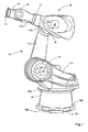
- Fig.1 shows a preferred embodiment of the inventive multi-axis robot 10 with at least one articulated arm 11.
- the articulated arm 11 has a total of four Gelenkarmabête 11 a, 11 b, 11 c, 11 d, which are connected via axles 14, 15 and a rotary joint 17 and be moved by an electric motor.
- the control of the axes 14, 15 and the pivot joint 17 via a arranged in the base 18 central control unit 181.
- the articulated arm 11 via a rotary joint 17 rotatable by 360 ° coupling point 13, in which the in Fig.1 not shown robot head 20 (see. Fig. 2 ) can be recorded.
- first axis 14 and a downstream second axis 15 of the robot head 20 in the X, Y, and Z direction can be pivoted by rotation about the first axis 14 also over head. This is particularly favorable for storing or picking up the robot head 20, for example when replacing it or for refilling the magazine units 30, 301 for the patches 40 (in FIG Fig.1 not shown).
- the coupling point 13 has a further joint 16, via which a pivoting of the coupling point 13 and the robot head 20 arranged thereon in the Z direction by almost 360 ° is made possible. With the in Fig. 1 shown robot 10 can thus be achieved all existing in the pivoting range of the articulated arm 11 flaws. This also applies to other multi-axis robot 10, z. Gantry robots, articulated arm robots (so-called scara construction) or hexapods.
- the articulated arm 11 is mounted on a platform 184 which is rotatably mounted 360 ° on a pedestal 18 which is fixed, for example next to a support for the wood workpiece (in Fig.1 not shown) can be mounted. It is also possible that the workpiece takes over in the manner of a bed milling machine part of the sliding movement to z. B. simultaneously with the robot movement to target a target and thus to further improve the repair speed.
- the base 18 on a movable carriage (in Fig.1 not shown) in order to move the robot 10 in the longitudinal direction of the workpiece can. For particularly simple mounting of the base 18, this has in its foot portion 182 projections 183 which can be locked with corresponding recesses at the installation.
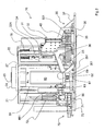
- a further preferred embodiment of the presented invention is shown.
- the robot head 20 here has a cylindrical robot head base unit 21 which has segments separated by outwardly extending frames 27 for arranging the respective tools or magazine units 30, 301.
- the robot head base unit 21 has on its upper side 24 a connection 25 for coupling with the coupling point 13, via which the connection between the robot arm 11 (see FIG. Fig.1 ) and robot head 20 is manufactured.
- the robot head 20 is also required for the operation of the tools, such as milling devices 70, 701, gluing device 60 and / or blower hydraulic, compressed air or power lines 26 a, b, c, d, e connected and made an electrical or wireless connection with the control unit 181.
- the tools such as milling devices 70, 701, gluing device 60 and / or blower hydraulic, compressed air or power lines 26 a, b, c, d, e connected and made an electrical or wireless connection with the control unit 181.
- the first magazine unit 30 for essentially ship-shaped or rod-shaped patches 40 for repairing defects in wood workpieces can be seen.
- the patches 40 are stored stacked in the magazine body 33 and are ejected downwardly as needed or pushed through the magazine.
- the magazine body 33 on guide rods 331 which rest against the outer edges of the patches 40 and prevent unwanted displacement of the patches 40.
- the pressing of a new patch 40 into the ejection position is carried out after pressurizing the remaining in the magazine body 33 patches 40 by a punch 31.
- the punch 31 is housed in a die housing 32 which can be pivoted laterally for refilling the first magazine unit 30 and then the magazine body 33rd releases, so that it can be fitted from above with new patches 40.
- the first magazine unit 30 has a base plate 35 and a back plate 36 perpendicular thereto. Base plate 35 and back plate 36 are connected via attached to the side edges 351, 361 fastener tape 37.
- the first magazine unit 30 is in the embodiment of Fig. 2 arranged on the cylindrical robot head base unit 21.
- the movable projections 34 arranged on the back plate 36 at the level of the stamp case 32 are engaged with the recesses 221 in the holding plates 22 provided on the robot head base unit 21 and automatically locked.
- the first magazine unit 30 is set down so that the base plate 35 rests, for example, on a support, the projections 34 are folded in and the first magazine unit 30 is released, so that it can be removed from the robot head base unit 21.
- a plug (not shown) is automatically connected to a corresponding receptacle 23 on the robot head base unit 21 and thus establishes a connection to the central control unit 181 of the robot 10 (cf. Fig.1 ) produced.
- An automatic hardware detection detects the position of the first magazine unit 30 and its shape for the subsequent integration of the first magazine unit 30 and the patches 40 stored therein in the current robot head configuration and in the planned work process.
- the robot head shown has a gluing device 60 arranged between the milling devices 70 and the magazine units 30, 301. About this 40 prepared by the respective cutter 71 flaw is glued before the insertion of the matching patch 40.
- the robot head 20 is rotated after retraction of the cutter 71 until the nozzle 61 of the gluing device 60 is above the defect.
- the robot head 20 is then lowered until the nozzle 61 projects into the defect.
- uniform pressure on the glue container 63 then exits a defined amount of glue from the nozzle 61 and is introduced into the defect.
- the robot head 20 travels along the contour of the defect during the glue application to ensure uniform gluing of the defect.
- the glue container 63 is inserted into a holder 69 and secured with a frame 64 against falling out of the holder 69.
- the frame 64 for glue delivery, for example via hydraulic or Pneumatikkmaschine o.ä. used to the robot head base unit 21.
- the glue is pressed through the nozzle 61 and finally exits from the glue container 63.
- the nozzle 61 is screwed via a cap nut 62 with the glue container 63.
- the quick release lever 66 is opened, the frame 64 folded away and the glue container 63 taken together with the nozzle 61 from the holder 69.
- the reusable nozzle 61 is either first cleaned or screwed back to a new glue container 63 with little contamination and used together with this in the holder 69.
- After insertion of the frame 64 of the quick release lever 66 is applied and the glue container 63 thereby preassembled to the filling of the nozzle 61 with glue.
- the quick release lever 66 is disposed on a guide 661, along which the quick release lever 66 can be moved.
- a milling device 70 is arranged on the in Fig. 2 left side of the robot head 20 shown.
- the robot head 20 first moves over the previously marked or detected defect. Subsequently, the side milling cutter 71 is extended out of the cutter housing 73 along a guide rail 72. After commissioning of the disc cutter 71, the robot head 20 is lowered onto the wood workpiece and the flaw is worked out.
- the robot head 20 travels the contour of the defect and milled so a groove into which then the matching patch 40 can be used.
- the disc milling cutter 71 is turned off, moved back to its rest position in the cutter housing 73 and blown out the defect by means of compressed air and thus freed from remaining chips.
- a rotation of the robot head 20 and the already described above gluing the elaborate flaw begins.
- a rotation of the robot head 20 and an alignment of the first magazine unit 30 on the defect After ejection from the magazine body 33, the patch 40 is pressed by slowly lowering the robot head 20 on the wood workpiece in the glued defect.
- the robot head 20 in the embodiment of FIG Fig. 2 on its side facing away from the viewer here back via a second magazine unit 301 for round patches 40.
- This second magazine unit 301 is also associated with a gluing device 60 and a second milling device 701.
- the second milling device 701 has in the example of Fig. 2 via an end mill (not shown). This can be extended or retracted by the spindle drive 75.
- the two milling devices 70, 701, like the magazine units 30, 301, can be coupled freely to the robot head base unit 21. The coupling takes place via the mechanism already described above for the first magazine unit 30. Again, the position and the execution of the respectively coupled milling device 70,701 is detected, released accordingly in the device control or disabled and taken into account in the device configuration and the flow logs.
- Fig. 3 shows the robot head 20 in front view.
- the robot head 20 has in this embodiment, the drum-shaped robot head base unit 21, to which a hexagonal cover plate 80 is screwed, which hides here the coupling points of the milling devices 70, 701 and the magazine units 30, 301.
- the Indian Fig. 3 shown robot head 20 has a total of six sides 201 for coupling tools. In the embodiment of only four pages 201 are equipped with tools. Also shown in plan view here are two of those already mentioned above, in Figure 3
- the first magazine unit 30 has two dispensing or ejection slots 39a, 39b for different long ship-shaped or rod-shaped patches 40.
- This first magazine unit 30 is in the exemplary embodiment a first milling device 70 with a disc cutter 71 (in Figure 3 not visible).
- the cutter housing 73 is covered at the top with a flap 77 and the disc cutter 71 is therefore not visible.
- the cutters 71 can be adjusted in height.
- guides 81 a, 81 b are provided, so that the cutter 71 can be manually moved along the guides 81 a, 81 b after loosening the clamping lever 78 a, 78 b.
- the first magazine unit 30 additionally has position sensors 304 to ensure the insertion of the patches 40 into the defect without tilting.
- the robot head 20 is lowered to just above the defect, the slide 332, which are provided on the ejection slots 39a, b, briefly open, with the opening of the slide 332, the remaining pressure in the magazine body 33 patches 40 and a patch 40 discharged from the magazine body 33.
- the patch 40 is pressed flush with the workpiece surface in the glued defect.
- the robot head 20 in the exemplary embodiment has the Figure 3 via a concentrically arranged on the robot head base unit ring 29.
- this compressed air connections 26a, b hydraulic connections 26c, d, respectively a power connection 26e and a connection for a data line 26f are provided, all after the coupling of the robot head 20 to the articulated arm 11 of the robot 10th be brought into engagement with the provided in the articulated arm 11 and the coupling point 13 of the articulated arm 11 connectors.
Landscapes
- Life Sciences & Earth Sciences (AREA)
- Engineering & Computer Science (AREA)
- Mechanical Engineering (AREA)
- Wood Science & Technology (AREA)
- Forests & Forestry (AREA)
- Manipulator (AREA)
- Laser Beam Processing (AREA)
Claims (9)
- Dispositif d'amélioration de défauts dans une pièce en bois, en particulier un lamellé-collé, sachant que le dispositif est réalisé comme un robot (10) à plusieurs axes, en particulier un robot à bras articulé et présente au moins une tête de robot (20), sachant que la tête de robot (20) présente au moins un outil de fraisage (70, 701) et au moins un magasin (30, 301) pour pastilles (40), en particulier des pastilles de bois, sachant que le dispositif présente des moyens pour l'enfoncement de la pastille (40), qui sont formés par la tête de robot (20) et/ou le robot (10).
- Dispositif selon la revendication 1,
caractérisé en ce que
la tête de robot (20) est réalisée comme une tourelle revolver rotative. - Dispositif selon l'une quelconque des revendications précédentes,
caractérisé en ce que
l'outil de fraisage (70, 701) et le magasin (30, 301) sont disposés de manière contiguë sur la périphérie de la tête de robot (20). - Dispositif selon l'une quelconque des revendications précédentes, caractérisé en ce qu'une pluralité de magasins (30, 301) pour pastilles (40) est disposée sur la tête de robot (20), sachant que les pastilles (40) présentent différentes déformations.
- Dispositif selon la revendication 4,
caractérisé en ce
qu'un outil de fraisage (70 ; 701) est associé à chaque magasin (30, 301) et sachant que l'outil de fraisage (70, 701) est adapté à la déformation de la pastille (40). - Dispositif selon l'une quelconque des revendications précédentes,
caractérisé en ce
qu'au moins un dispositif de soufflage et/ou un dispositif de collage (60) est/sont prévus sur la tête de robot (20). - Dispositif selon l'une quelconque des revendications précédentes,
caractérisé en ce que
la tête de robot (20) présente au moins un dispositif d'aspiration. - Dispositif selon l'une quelconque des revendications précédentes,
caractérisé en ce que
la tête de robot (20) présente un organe de palpage pour la position, la grandeur et la déformation du défaut. - Dispositif selon l'une quelconque des revendications précédentes, caractérisé en ce que l'outil de fraisage (70, 701) présente une position de travail avancée et l'avancement dans le défaut peut être réalisée par le robot (10).
Applications Claiming Priority (1)
| Application Number | Priority Date | Filing Date | Title |
|---|---|---|---|
| DE202007005516U DE202007005516U1 (de) | 2007-04-14 | 2007-04-14 | Vorrichtung zum Ausbessern von Fehlstellen in einem Holzwerkstück |
Publications (2)
| Publication Number | Publication Date |
|---|---|
| EP1982808A1 EP1982808A1 (fr) | 2008-10-22 |
| EP1982808B1 true EP1982808B1 (fr) | 2012-01-11 |
Family
ID=39400115
Family Applications (1)
| Application Number | Title | Priority Date | Filing Date |
|---|---|---|---|
| EP08007287A Active EP1982808B1 (fr) | 2007-04-14 | 2008-04-14 | Dispositif d'amélioration de défauts dans une pièce en bois |
Country Status (3)
| Country | Link |
|---|---|
| EP (1) | EP1982808B1 (fr) |
| AT (1) | ATE540791T1 (fr) |
| DE (1) | DE202007005516U1 (fr) |
Cited By (1)
| Publication number | Priority date | Publication date | Assignee | Title |
|---|---|---|---|---|
| US11931916B2 (en) | 2018-02-09 | 2024-03-19 | Fill Gesellschaft M.B.H. | Repair device, and method for repairing a defect in a wooden workpiece |
Families Citing this family (9)
| Publication number | Priority date | Publication date | Assignee | Title |
|---|---|---|---|---|
| AT514062B1 (de) * | 2013-08-19 | 2014-10-15 | Gruber Automations Gmbh | Anlage zum Ausbessern von Fehlstellen in Hölzern |
| CN105291213B (zh) * | 2015-11-25 | 2017-07-07 | 南京林业大学 | 一种木材表面缺陷的智能挖补装置 |
| CN107454545A (zh) * | 2017-08-18 | 2017-12-08 | 深圳斯维德科技有限公司 | 一种耳机背胶全自动贴合机 |
| CN107584813A (zh) * | 2017-10-30 | 2018-01-16 | 天津远达滤清器股份有限公司 | 一种过滤纸的检测贴补系统 |
| IT202100013991A1 (it) * | 2021-05-28 | 2022-11-28 | Bre Ma Brenna Macch S R L | Unita' inseritrice per l'inserimento di articoli di ferramenta per mobili in pannelli di legno o simili |
| IT202100013976A1 (it) * | 2021-05-28 | 2022-11-28 | Bre Ma Brenna Macch S R L | Unita' inseritrice per l'inserimento di articoli di ferramenta per mobili in pannelli di legno o simili |
| EP4094912B1 (fr) * | 2021-05-28 | 2024-12-25 | BIESSE S.p.A. | Unité d'insertion d'articles matériels de mobilier dans des panneaux en bois ou similaire |
| CN113579940B (zh) * | 2021-07-08 | 2023-11-17 | 青岛森晨木业有限责任公司 | 防腐木材的缺陷处理设备 |
| CN117400383A (zh) * | 2023-10-23 | 2024-01-16 | 中建三局集团(深圳)有限公司 | 一种高性能建筑支撑龙骨生产工艺 |
Family Cites Families (3)
| Publication number | Priority date | Publication date | Assignee | Title |
|---|---|---|---|---|
| IT1204492B (it) | 1986-03-21 | 1989-03-01 | Cremona Lorenzo | Sistema per il rilevamento e l'eliminazione di difetti presenti in manufatti in lavorazione,in particolare pannelli di legno con cricche e ripieghi che devono essere stuccati |
| DE19637177C2 (de) * | 1996-09-12 | 2000-06-08 | Fraunhofer Ges Forschung | Vorrichtung für eine Werkzeugmaschine zur automatischen Bearbeitung von Werkstücken und Montage von Verbindungselementen |
| DE10223831B4 (de) | 2001-06-01 | 2015-12-10 | H.I.T. Bertele Gmbh + Co. | Vorrichtung zum Bearbeiten von Leimbindern und anderen Holzwerkstoffen |
-
2007
- 2007-04-14 DE DE202007005516U patent/DE202007005516U1/de not_active Expired - Lifetime
-
2008
- 2008-04-14 AT AT08007287T patent/ATE540791T1/de active
- 2008-04-14 EP EP08007287A patent/EP1982808B1/fr active Active
Cited By (1)
| Publication number | Priority date | Publication date | Assignee | Title |
|---|---|---|---|---|
| US11931916B2 (en) | 2018-02-09 | 2024-03-19 | Fill Gesellschaft M.B.H. | Repair device, and method for repairing a defect in a wooden workpiece |
Also Published As
| Publication number | Publication date |
|---|---|
| EP1982808A1 (fr) | 2008-10-22 |
| DE202007005516U1 (de) | 2008-05-15 |
| ATE540791T1 (de) | 2012-01-15 |
Similar Documents
| Publication | Publication Date | Title |
|---|---|---|
| EP1982808B1 (fr) | Dispositif d'amélioration de défauts dans une pièce en bois | |
| EP3096921B1 (fr) | Dispositif d'usinage pour la fabrication et l'usinage assistés par ordinateur de pièces dentaires | |
| DE102013106427B4 (de) | Verfahren zum Bereitstellen von Werkmitteln und Ladesystem zur Durchführung des Verfahrens | |
| EP1798019B1 (fr) | Dispositif pour réaliser des travaux d'estampage, de fraisage, de soudage ou bien de collage sur des pièces en plastique tridimensionnelles de grandes dimensions | |
| EP2950956A2 (fr) | Procédé de fabrication d'une copie de clé | |
| DE10223831B4 (de) | Vorrichtung zum Bearbeiten von Leimbindern und anderen Holzwerkstoffen | |
| DE20321663U1 (de) | CNC-Bearbeitungsmaschine zum Aufteilen großformatiger Platten | |
| EP1125670B1 (fr) | Dispositif à ébarber, en particulier pour des cordons de soudure | |
| DE202006021287U1 (de) | Arbeitsmaschine zum Bearbeiten von Holzelementen | |
| DE102016124892B4 (de) | Bearbeitungsvorrichtung mit einer programmtechnischen Steuerung | |
| EP3513932A1 (fr) | Procédé de fabrication d'éléments muraux à partir de matières clouables et / ou serrables | |
| DE202009016497U1 (de) | Vorrichtung zum Ausbessern von Fehlstellen in Holz | |
| DE102014100476A1 (de) | Roboter-Stanzzelle | |
| DE19548431C2 (de) | Vorrichtung für die automatische Fertigung von Aussparungen und Montage von Einpresselementen, wie z.B. Holz- oder Kunststoffdübel | |
| AT520093B1 (de) | Ausbesserungsvorrichtung, sowie Verfahren zum Ausbessern einer Fehlstelle in einem Holzwerkstück | |
| EP1792696A1 (fr) | Dispositif et procédé pour réparer un défaut dans une pièce en bois | |
| DE19826342A1 (de) | Plattenbearbeitungsmaschine | |
| DE102009053420A1 (de) | Verfahren und Vorrichtung für das Herstellen eines Endprodukts in einer Folding-Technik | |
| EP0432857A2 (fr) | Machine-outil à course courte, munie d'une broche à forer et à fraiser qui est déplaçable par rapport au châssis de la machine | |
| DE19813261B4 (de) | Verfahren und Vorrichtung zur Befestigung eines Dreh/Kippbeschlages | |
| EP4497046A1 (fr) | Procédé de vérification d'un processus d'usinage pour des collisions au moyen d'une pièce de remplacement | |
| EP1779990A2 (fr) | Dispositif d'usinage de cadres de fenêtre | |
| DE102024123449A1 (de) | Portalwerkzeugmaschine mit wenigstens einem mitfahrenden Magazin für Werkzeuge | |
| DE19602937A1 (de) | Lackzwischenschleifmaschine und Verfahren zum Lackzwischenschleifen | |
| WO2019129478A1 (fr) | Machine et procédé pour enduire des pièces |
Legal Events
| Date | Code | Title | Description |
|---|---|---|---|
| PUAI | Public reference made under article 153(3) epc to a published international application that has entered the european phase |
Free format text: ORIGINAL CODE: 0009012 |
|
| AK | Designated contracting states |
Kind code of ref document: A1 Designated state(s): AT BE BG CH CY CZ DE DK EE ES FI FR GB GR HR HU IE IS IT LI LT LU LV MC MT NL NO PL PT RO SE SI SK TR |
|
| AX | Request for extension of the european patent |
Extension state: AL BA MK RS |
|
| 17P | Request for examination filed |
Effective date: 20090413 |
|
| 17Q | First examination report despatched |
Effective date: 20090526 |
|
| AKX | Designation fees paid |
Designated state(s): AT BE BG CH CY CZ DE DK EE ES FI FR GB GR HR HU IE IS IT LI LT LU LV MC MT NL NO PL PT RO SE SI SK TR |
|
| GRAP | Despatch of communication of intention to grant a patent |
Free format text: ORIGINAL CODE: EPIDOSNIGR1 |
|
| GRAS | Grant fee paid |
Free format text: ORIGINAL CODE: EPIDOSNIGR3 |
|
| GRAA | (expected) grant |
Free format text: ORIGINAL CODE: 0009210 |
|
| AK | Designated contracting states |
Kind code of ref document: B1 Designated state(s): AT BE BG CH CY CZ DE DK EE ES FI FR GB GR HR HU IE IS IT LI LT LU LV MC MT NL NO PL PT RO SE SI SK TR |
|
| REG | Reference to a national code |
Ref country code: GB Ref legal event code: FG4D Free format text: NOT ENGLISH |
|
| REG | Reference to a national code |
Ref country code: CH Ref legal event code: EP |
|
| REG | Reference to a national code |
Ref country code: AT Ref legal event code: REF Ref document number: 540791 Country of ref document: AT Kind code of ref document: T Effective date: 20120115 |
|
| REG | Reference to a national code |
Ref country code: IE Ref legal event code: FG4D |
|
| REG | Reference to a national code |
Ref country code: DE Ref legal event code: R096 Ref document number: 502008006076 Country of ref document: DE Effective date: 20120315 |
|
| REG | Reference to a national code |
Ref country code: SE Ref legal event code: TRGR |
|
| REG | Reference to a national code |
Ref country code: NL Ref legal event code: VDEP Effective date: 20120111 |
|
| REG | Reference to a national code |
Ref country code: NO Ref legal event code: T2 Effective date: 20120111 |
|
| PG25 | Lapsed in a contracting state [announced via postgrant information from national office to epo] |
Ref country code: SI Free format text: LAPSE BECAUSE OF FAILURE TO SUBMIT A TRANSLATION OF THE DESCRIPTION OR TO PAY THE FEE WITHIN THE PRESCRIBED TIME-LIMIT Effective date: 20120111 |
|
| LTIE | Lt: invalidation of european patent or patent extension |
Effective date: 20120111 |
|
| PG25 | Lapsed in a contracting state [announced via postgrant information from national office to epo] |
Ref country code: HR Free format text: LAPSE BECAUSE OF FAILURE TO SUBMIT A TRANSLATION OF THE DESCRIPTION OR TO PAY THE FEE WITHIN THE PRESCRIBED TIME-LIMIT Effective date: 20120111 Ref country code: NL Free format text: LAPSE BECAUSE OF FAILURE TO SUBMIT A TRANSLATION OF THE DESCRIPTION OR TO PAY THE FEE WITHIN THE PRESCRIBED TIME-LIMIT Effective date: 20120111 Ref country code: LT Free format text: LAPSE BECAUSE OF FAILURE TO SUBMIT A TRANSLATION OF THE DESCRIPTION OR TO PAY THE FEE WITHIN THE PRESCRIBED TIME-LIMIT Effective date: 20120111 Ref country code: BG Free format text: LAPSE BECAUSE OF FAILURE TO SUBMIT A TRANSLATION OF THE DESCRIPTION OR TO PAY THE FEE WITHIN THE PRESCRIBED TIME-LIMIT Effective date: 20120411 Ref country code: IS Free format text: LAPSE BECAUSE OF FAILURE TO SUBMIT A TRANSLATION OF THE DESCRIPTION OR TO PAY THE FEE WITHIN THE PRESCRIBED TIME-LIMIT Effective date: 20120511 |
|
| REG | Reference to a national code |
Ref country code: IE Ref legal event code: FD4D |
|
| PG25 | Lapsed in a contracting state [announced via postgrant information from national office to epo] |
Ref country code: LV Free format text: LAPSE BECAUSE OF FAILURE TO SUBMIT A TRANSLATION OF THE DESCRIPTION OR TO PAY THE FEE WITHIN THE PRESCRIBED TIME-LIMIT Effective date: 20120111 Ref country code: PL Free format text: LAPSE BECAUSE OF FAILURE TO SUBMIT A TRANSLATION OF THE DESCRIPTION OR TO PAY THE FEE WITHIN THE PRESCRIBED TIME-LIMIT Effective date: 20120111 Ref country code: GR Free format text: LAPSE BECAUSE OF FAILURE TO SUBMIT A TRANSLATION OF THE DESCRIPTION OR TO PAY THE FEE WITHIN THE PRESCRIBED TIME-LIMIT Effective date: 20120412 Ref country code: PT Free format text: LAPSE BECAUSE OF FAILURE TO SUBMIT A TRANSLATION OF THE DESCRIPTION OR TO PAY THE FEE WITHIN THE PRESCRIBED TIME-LIMIT Effective date: 20120511 |
|
| PG25 | Lapsed in a contracting state [announced via postgrant information from national office to epo] |
Ref country code: CY Free format text: LAPSE BECAUSE OF FAILURE TO SUBMIT A TRANSLATION OF THE DESCRIPTION OR TO PAY THE FEE WITHIN THE PRESCRIBED TIME-LIMIT Effective date: 20120111 |
|
| BERE | Be: lapsed |
Owner name: H.I.T. MASCHINENBAU G.M.B.H. + CO. KG Effective date: 20120430 |
|
| PG25 | Lapsed in a contracting state [announced via postgrant information from national office to epo] |
Ref country code: EE Free format text: LAPSE BECAUSE OF FAILURE TO SUBMIT A TRANSLATION OF THE DESCRIPTION OR TO PAY THE FEE WITHIN THE PRESCRIBED TIME-LIMIT Effective date: 20120111 Ref country code: CZ Free format text: LAPSE BECAUSE OF FAILURE TO SUBMIT A TRANSLATION OF THE DESCRIPTION OR TO PAY THE FEE WITHIN THE PRESCRIBED TIME-LIMIT Effective date: 20120111 Ref country code: IE Free format text: LAPSE BECAUSE OF FAILURE TO SUBMIT A TRANSLATION OF THE DESCRIPTION OR TO PAY THE FEE WITHIN THE PRESCRIBED TIME-LIMIT Effective date: 20120111 Ref country code: RO Free format text: LAPSE BECAUSE OF FAILURE TO SUBMIT A TRANSLATION OF THE DESCRIPTION OR TO PAY THE FEE WITHIN THE PRESCRIBED TIME-LIMIT Effective date: 20120111 Ref country code: DK Free format text: LAPSE BECAUSE OF FAILURE TO SUBMIT A TRANSLATION OF THE DESCRIPTION OR TO PAY THE FEE WITHIN THE PRESCRIBED TIME-LIMIT Effective date: 20120111 |
|
| PLBE | No opposition filed within time limit |
Free format text: ORIGINAL CODE: 0009261 |
|
| STAA | Information on the status of an ep patent application or granted ep patent |
Free format text: STATUS: NO OPPOSITION FILED WITHIN TIME LIMIT |
|
| PG25 | Lapsed in a contracting state [announced via postgrant information from national office to epo] |
Ref country code: MC Free format text: LAPSE BECAUSE OF NON-PAYMENT OF DUE FEES Effective date: 20120430 Ref country code: SK Free format text: LAPSE BECAUSE OF FAILURE TO SUBMIT A TRANSLATION OF THE DESCRIPTION OR TO PAY THE FEE WITHIN THE PRESCRIBED TIME-LIMIT Effective date: 20120111 |
|
| 26N | No opposition filed |
Effective date: 20121012 |
|
| GBPC | Gb: european patent ceased through non-payment of renewal fee |
Effective date: 20120414 |
|
| PG25 | Lapsed in a contracting state [announced via postgrant information from national office to epo] |
Ref country code: GB Free format text: LAPSE BECAUSE OF NON-PAYMENT OF DUE FEES Effective date: 20120414 Ref country code: BE Free format text: LAPSE BECAUSE OF NON-PAYMENT OF DUE FEES Effective date: 20120430 |
|
| REG | Reference to a national code |
Ref country code: DE Ref legal event code: R097 Ref document number: 502008006076 Country of ref document: DE Effective date: 20121012 |
|
| REG | Reference to a national code |
Ref country code: CH Ref legal event code: PUE Owner name: FILL GESELLSCHAFT M.B.H., AT Free format text: FORMER OWNER: H.I.T. MASCHINENBAU GMBH + CO. KG, DE |
|
| PG25 | Lapsed in a contracting state [announced via postgrant information from national office to epo] |
Ref country code: ES Free format text: LAPSE BECAUSE OF FAILURE TO SUBMIT A TRANSLATION OF THE DESCRIPTION OR TO PAY THE FEE WITHIN THE PRESCRIBED TIME-LIMIT Effective date: 20120422 |
|
| REG | Reference to a national code |
Ref country code: DE Ref legal event code: R081 Ref document number: 502008006076 Country of ref document: DE Owner name: FILL GESELLSCHAFT M.B.H., AT Free format text: FORMER OWNER: H.I.T. MASCHINENBAU GMBH + CO. KG, 86833 ETTRINGEN, DE Effective date: 20130411 Ref country code: DE Ref legal event code: R082 Ref document number: 502008006076 Country of ref document: DE Representative=s name: CREMER & CREMER, DE Effective date: 20130411 |
|
| REG | Reference to a national code |
Ref country code: FR Ref legal event code: TP Owner name: FILL GESELLSCHAFT M.B.H., AT Effective date: 20130516 |
|
| REG | Reference to a national code |
Ref country code: NO Ref legal event code: CHAD Owner name: FILL GESELLSCHAFT MBH, AT |
|
| PG25 | Lapsed in a contracting state [announced via postgrant information from national office to epo] |
Ref country code: MT Free format text: LAPSE BECAUSE OF FAILURE TO SUBMIT A TRANSLATION OF THE DESCRIPTION OR TO PAY THE FEE WITHIN THE PRESCRIBED TIME-LIMIT Effective date: 20120111 |
|
| REG | Reference to a national code |
Ref country code: AT Ref legal event code: PC Ref document number: 540791 Country of ref document: AT Kind code of ref document: T Owner name: FILL GESELLSCHAFT M.B.H., AT Effective date: 20131009 |
|
| PG25 | Lapsed in a contracting state [announced via postgrant information from national office to epo] |
Ref country code: TR Free format text: LAPSE BECAUSE OF FAILURE TO SUBMIT A TRANSLATION OF THE DESCRIPTION OR TO PAY THE FEE WITHIN THE PRESCRIBED TIME-LIMIT Effective date: 20120111 |
|
| PG25 | Lapsed in a contracting state [announced via postgrant information from national office to epo] |
Ref country code: LU Free format text: LAPSE BECAUSE OF NON-PAYMENT OF DUE FEES Effective date: 20120414 |
|
| PG25 | Lapsed in a contracting state [announced via postgrant information from national office to epo] |
Ref country code: HU Free format text: LAPSE BECAUSE OF FAILURE TO SUBMIT A TRANSLATION OF THE DESCRIPTION OR TO PAY THE FEE WITHIN THE PRESCRIBED TIME-LIMIT Effective date: 20080414 |
|
| REG | Reference to a national code |
Ref country code: CH Ref legal event code: NV Representative=s name: ABP PATENT NETWORK AG, CH |
|
| REG | Reference to a national code |
Ref country code: FR Ref legal event code: PLFP Year of fee payment: 9 |
|
| REG | Reference to a national code |
Ref country code: FR Ref legal event code: PLFP Year of fee payment: 10 |
|
| PGFP | Annual fee paid to national office [announced via postgrant information from national office to epo] |
Ref country code: FR Payment date: 20170329 Year of fee payment: 10 Ref country code: SE Payment date: 20170329 Year of fee payment: 10 Ref country code: NO Payment date: 20170314 Year of fee payment: 10 |
|
| REG | Reference to a national code |
Ref country code: CH Ref legal event code: PCAR Free format text: NEW ADDRESS: OTHMARSTRASSE 8, 8008 ZUERICH (CH) |
|
| REG | Reference to a national code |
Ref country code: NO Ref legal event code: MMEP |
|
| REG | Reference to a national code |
Ref country code: SE Ref legal event code: EUG |
|
| PG25 | Lapsed in a contracting state [announced via postgrant information from national office to epo] |
Ref country code: SE Free format text: LAPSE BECAUSE OF NON-PAYMENT OF DUE FEES Effective date: 20180415 Ref country code: NO Free format text: LAPSE BECAUSE OF NON-PAYMENT OF DUE FEES Effective date: 20180430 |
|
| REG | Reference to a national code |
Ref country code: DE Ref legal event code: R082 Ref document number: 502008006076 Country of ref document: DE Representative=s name: ABP BURGER RECHTSANWALTSGESELLSCHAFT MBH, DE |
|
| PG25 | Lapsed in a contracting state [announced via postgrant information from national office to epo] |
Ref country code: FR Free format text: LAPSE BECAUSE OF NON-PAYMENT OF DUE FEES Effective date: 20180430 |
|
| PGFP | Annual fee paid to national office [announced via postgrant information from national office to epo] |
Ref country code: FI Payment date: 20250423 Year of fee payment: 18 |
|
| PGFP | Annual fee paid to national office [announced via postgrant information from national office to epo] |
Ref country code: DE Payment date: 20250418 Year of fee payment: 18 |
|
| PGFP | Annual fee paid to national office [announced via postgrant information from national office to epo] |
Ref country code: IT Payment date: 20250418 Year of fee payment: 18 |
|
| PGFP | Annual fee paid to national office [announced via postgrant information from national office to epo] |
Ref country code: CH Payment date: 20250522 Year of fee payment: 18 |
|
| PGFP | Annual fee paid to national office [announced via postgrant information from national office to epo] |
Ref country code: AT Payment date: 20250423 Year of fee payment: 18 |