EP1982836A2 - Commande de position de rinçage incorporé dans un appareil d'enregistrement à jet d'encre et méthode de rinçage utilisé à cet effet - Google Patents
Commande de position de rinçage incorporé dans un appareil d'enregistrement à jet d'encre et méthode de rinçage utilisé à cet effet Download PDFInfo
- Publication number
- EP1982836A2 EP1982836A2 EP08161992A EP08161992A EP1982836A2 EP 1982836 A2 EP1982836 A2 EP 1982836A2 EP 08161992 A EP08161992 A EP 08161992A EP 08161992 A EP08161992 A EP 08161992A EP 1982836 A2 EP1982836 A2 EP 1982836A2
- Authority
- EP
- European Patent Office
- Prior art keywords
- ink
- flushing
- recording apparatus
- jet recording
- set forth
- Prior art date
- Legal status (The legal status is an assumption and is not a legal conclusion. Google has not performed a legal analysis and makes no representation as to the accuracy of the status listed.)
- Withdrawn
Links
Images





Classifications
-
- B—PERFORMING OPERATIONS; TRANSPORTING
- B41—PRINTING; LINING MACHINES; TYPEWRITERS; STAMPS
- B41J—TYPEWRITERS; SELECTIVE PRINTING MECHANISMS, i.e. MECHANISMS PRINTING OTHERWISE THAN FROM A FORME; CORRECTION OF TYPOGRAPHICAL ERRORS
- B41J2/00—Typewriters or selective printing mechanisms characterised by the printing or marking process for which they are designed
- B41J2/005—Typewriters or selective printing mechanisms characterised by the printing or marking process for which they are designed characterised by bringing liquid or particles selectively into contact with a printing material
- B41J2/01—Ink jet
- B41J2/17—Ink jet characterised by ink handling
- B41J2/1721—Collecting waste ink; Collectors therefor
-
- B—PERFORMING OPERATIONS; TRANSPORTING
- B41—PRINTING; LINING MACHINES; TYPEWRITERS; STAMPS
- B41J—TYPEWRITERS; SELECTIVE PRINTING MECHANISMS, i.e. MECHANISMS PRINTING OTHERWISE THAN FROM A FORME; CORRECTION OF TYPOGRAPHICAL ERRORS
- B41J2/00—Typewriters or selective printing mechanisms characterised by the printing or marking process for which they are designed
- B41J2/005—Typewriters or selective printing mechanisms characterised by the printing or marking process for which they are designed characterised by bringing liquid or particles selectively into contact with a printing material
- B41J2/01—Ink jet
- B41J2/135—Nozzles
- B41J2/165—Prevention or detection of nozzle clogging, e.g. cleaning, capping or moistening for nozzles
- B41J2/16505—Caps, spittoons or covers for cleaning or preventing drying out
- B41J2/16508—Caps, spittoons or covers for cleaning or preventing drying out connected with the printer frame
-
- B—PERFORMING OPERATIONS; TRANSPORTING
- B41—PRINTING; LINING MACHINES; TYPEWRITERS; STAMPS
- B41J—TYPEWRITERS; SELECTIVE PRINTING MECHANISMS, i.e. MECHANISMS PRINTING OTHERWISE THAN FROM A FORME; CORRECTION OF TYPOGRAPHICAL ERRORS
- B41J2/00—Typewriters or selective printing mechanisms characterised by the printing or marking process for which they are designed
- B41J2/005—Typewriters or selective printing mechanisms characterised by the printing or marking process for which they are designed characterised by bringing liquid or particles selectively into contact with a printing material
- B41J2/01—Ink jet
- B41J2/17—Ink jet characterised by ink handling
- B41J2/1721—Collecting waste ink; Collectors therefor
- B41J2/1728—Closed waste ink collectors
-
- B—PERFORMING OPERATIONS; TRANSPORTING
- B41—PRINTING; LINING MACHINES; TYPEWRITERS; STAMPS
- B41J—TYPEWRITERS; SELECTIVE PRINTING MECHANISMS, i.e. MECHANISMS PRINTING OTHERWISE THAN FROM A FORME; CORRECTION OF TYPOGRAPHICAL ERRORS
- B41J2/00—Typewriters or selective printing mechanisms characterised by the printing or marking process for which they are designed
- B41J2/005—Typewriters or selective printing mechanisms characterised by the printing or marking process for which they are designed characterised by bringing liquid or particles selectively into contact with a printing material
- B41J2/01—Ink jet
- B41J2/17—Ink jet characterised by ink handling
- B41J2/1721—Collecting waste ink; Collectors therefor
- B41J2/1742—Open waste ink collectors, e.g. ink receiving from a print head above the collector during borderless printing
Definitions
- the ink-jet recording apparatus is equipped with a capping member for sealing the nozzle orifices of the recording head while the recording apparatus is in a non-printing mode, and a cleaning device for cleaning a nozzle plate, as required.
- the cleaning operation is performed when a printing operation is resumed after the recording apparatus has remained in an idle mode for a long period of time or when the user actuates a cleaning switch for eliminating degradation in the quality of a recorded image.
- the cleaning operation involves removal of ink droplets from the recording head by means of negative pressure applied through suction, and wiping of the surface of the recording head by means of a wiping blade formed from rubber or an elastic plate.
- the recording head may be flushed within the capping member 10 or in the flushing region 13A constituted of the aperture formed in the paper guide member 8.
- the recording head is flushed within the flushing region in order to prevent an overflow of ink, which would otherwise be caused when ink droplets are continuously ejected after the capping member 10 has already been filled with ink.
- the related ink-jet recording apparatus is required to temporarily suspend a printing operation in order to flush the recording head, move the carriage to the capping member or the flushing region, return the carriage to the position where the printing operation was interrupted, after flushing of the recording head is completed, and resume the printing operation.
- the related recording apparatus encounters technological problems; i.e., a deterioration in throughput associated with the flushing operation; and an increase in print time.
- ink droplets ejected from the nozzle orifices of the recording head turn into mist as a result of air resistance and are suspended in air before arrival at the ink-absorbing member 14, thus staining the surroundings.
- Ink droplets ejected from the nozzle orifices are electrically charged to a considerably degree.
- the ink droplets are affected by the electrostatic charge developed in a drive section of the recording apparatus and are accelerated by an air flow induced by an exhaust fan disposed for preventing an increase in the internal temperature of the recording apparatus or an air flow resulting from movement of the carriage, thus staining as well the (external) area surrounding the recording apparatus.
- a processing routine employed for the flushing operation comprises a step of deactivating a carriage motor within a predetermined flushing region and flushing a recording head, and a step of performing a print operation. As mentioned above, such a processing routine encounters a difficulty in increasing throughput.
- an ink-jet recording apparatus comprising:
- a distance between the porous sheet member and a surface on which the nozzle orifices are formed is set within a domain of 1 to 5 mm when the flushing operation is performed.
- the periphery of the porous sheet member is enclosed by a case.
- the ink ejected during flushing operation flows along the interior of the case and is absorbed by the ink absorbing member.
- the lower end of the porous sheet member is partially notched such that an opening is defined by the notch and the inner face of the casing.
- the porous sheet member is secured to the casing by a fixing member.
- the fixing member is situated so as not to face the nozzle forming surface when the flushing operation is performed.
- the present invention enables solving of a problem; i.e., staining of the interior or exterior of the ink-jet recording apparatus, which would otherwise be caused by the mist.
- the first flushing is performed without stopping the carriage.
- the flushing method is particularly desirable because it can prevent cumulative deposition of ink by changing the first and second positions.
- the respective apertures are larger than a size of surface on which the nozzle orifices are formed.
- the ink ejected from the recording head 5 for flushing purpose within the flushing region 13A or 13B is absorbed by the ink-absorbing member 14 housed in the waste-ink tank 15.
- the ink adhering to the slant surface 20a becomes ink droplets as a result of the water-repellent layer formed on the slant surface 20a and falls to the ink-absorbing member 14. Accordingly, the ink-absorbing member 14 can be made compact.
- the ink receiver unit 127 is attached to the recording apparatus such that an axial line 131 c of the second cylindrical body 131b is aligned substantially normal to the recording apparatus.
- the present invention is not limited to such a specific type of recording apparatus. Needless to say, the same working-effect can be yielded even when the present invention is applied to another type of ink-jet recording apparatus.
- black ink has a higher solid concentration than do yellow ink, cyan ink, and magenta ink, the black ink is susceptible to an increase in viscosity and is likely to solidify when solvent contained in the black ink evaporates.
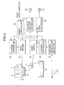
- the flushing controller 32 sends a control signal to the carriage position controller 37, which in turn sends a control signal, thus activating the pulse motor for moving the carriage 1.
- the carriage 1 is moved to position B shown in Fig. 12 (called a second position), where the carriage 1 is stopped.
- the carriage position controller 37 sends a control signal to the flushing controller 32, whereupon the nozzle orifices 5b, 5c, and 5d, which are assigned to yellow ink, cyan ink, and magenta ink, respectively, eject these colors of ink.
- One end of the area over which the recording heads 112a and 112b mounted on the carriage 111 travel corresponds to a non-print region (the home position), where capping member 121 is disposed.
- the flushing positions of recording heads may be determined by means similar to those mentioned previously, even in the case of a recording apparatus equipped with three or more recording heads.
Landscapes
- Ink Jet (AREA)
Applications Claiming Priority (6)
| Application Number | Priority Date | Filing Date | Title |
|---|---|---|---|
| JP33102698A JP3707274B2 (ja) | 1998-11-20 | 1998-11-20 | インクジェット式記録装置 |
| JP10338015A JP2000158677A (ja) | 1998-11-27 | 1998-11-27 | インクジェット式記録装置におけるフラッシング位置調整装置 |
| JP34307998A JP3598513B2 (ja) | 1998-12-02 | 1998-12-02 | インクジェット式記録装置 |
| JP35906898A JP3543316B2 (ja) | 1998-12-17 | 1998-12-17 | インクジェット式記録装置 |
| JP8692199A JP3669197B2 (ja) | 1999-03-29 | 1999-03-29 | インクジェット式記録装置のフラッシング方法及びインクジェット式記録装置 |
| EP99123128A EP1002648A1 (fr) | 1998-11-20 | 1999-11-19 | Commande de position de rinçage incorporé dans un appareil d'enregistrement à jet d'encre et méthode de rinçage utilisé à cet effet |
Related Parent Applications (1)
| Application Number | Title | Priority Date | Filing Date |
|---|---|---|---|
| EP99123128A Division EP1002648A1 (fr) | 1998-11-20 | 1999-11-19 | Commande de position de rinçage incorporé dans un appareil d'enregistrement à jet d'encre et méthode de rinçage utilisé à cet effet |
Publications (2)
| Publication Number | Publication Date |
|---|---|
| EP1982836A2 true EP1982836A2 (fr) | 2008-10-22 |
| EP1982836A3 EP1982836A3 (fr) | 2009-01-28 |
Family
ID=27525246
Family Applications (2)
| Application Number | Title | Priority Date | Filing Date |
|---|---|---|---|
| EP99123128A Withdrawn EP1002648A1 (fr) | 1998-11-20 | 1999-11-19 | Commande de position de rinçage incorporé dans un appareil d'enregistrement à jet d'encre et méthode de rinçage utilisé à cet effet |
| EP08161992A Withdrawn EP1982836A3 (fr) | 1998-11-20 | 1999-11-19 | Commande de position de rinçage incorporé dans un appareil d'enregistrement à jet d'encre et méthode de rinçage utilisé à cet effet |
Family Applications Before (1)
| Application Number | Title | Priority Date | Filing Date |
|---|---|---|---|
| EP99123128A Withdrawn EP1002648A1 (fr) | 1998-11-20 | 1999-11-19 | Commande de position de rinçage incorporé dans un appareil d'enregistrement à jet d'encre et méthode de rinçage utilisé à cet effet |
Country Status (1)
| Country | Link |
|---|---|
| EP (2) | EP1002648A1 (fr) |
Cited By (3)
| Publication number | Priority date | Publication date | Assignee | Title |
|---|---|---|---|---|
| CN102248784A (zh) * | 2010-05-18 | 2011-11-23 | 精工爱普生株式会社 | 流体喷射装置 |
| CN102398416A (zh) * | 2010-09-09 | 2012-04-04 | 精工爱普生株式会社 | 液体喷出装置以及液体喷出方法 |
| CN102555451A (zh) * | 2010-09-14 | 2012-07-11 | 精工爱普生株式会社 | 液体喷出装置以及液体喷出方法 |
Families Citing this family (3)
| Publication number | Priority date | Publication date | Assignee | Title |
|---|---|---|---|---|
| US6663219B2 (en) | 2000-06-01 | 2003-12-16 | Canon Kabushiki Kaisha | Inkjet recording apparatus |
| EP1195252B1 (fr) | 2000-10-04 | 2005-05-18 | Canon Kabushiki Kaisha | Dispositif de remise en état pour une tête, procédé de restauration d'une tête et un appareil à jet d'encre |
| CN115610103B (zh) * | 2022-12-06 | 2023-03-17 | 苏州优备精密智能装备股份有限公司 | 防止墨滴打印时发生漂移的装置及其方法 |
Family Cites Families (8)
| Publication number | Priority date | Publication date | Assignee | Title |
|---|---|---|---|---|
| US5717444A (en) * | 1990-04-11 | 1998-02-10 | Canon Kabushiki Kaisha | Suction recovery device and ink jet recording apparatus using the device |
| JP2839966B2 (ja) * | 1990-08-17 | 1998-12-24 | キヤノン株式会社 | インクジェット記録装置の回復方法およびインクジェット記録装置 |
| DE69322459T2 (de) * | 1992-09-03 | 1999-06-02 | Canon K.K., Tokio/Tokyo | Farbstrahlaufzeichnungsgerät |
| JP3391924B2 (ja) * | 1995-01-31 | 2003-03-31 | キヤノン株式会社 | 画像記録装置 |
| JP3467716B2 (ja) * | 1995-05-25 | 2003-11-17 | セイコーエプソン株式会社 | インクジェット記録ヘッド用キャッピング装置 |
| JP3229925B2 (ja) * | 1996-06-07 | 2001-11-19 | シチズン時計株式会社 | メンテキャップ |
| DE69717203T2 (de) * | 1996-07-30 | 2003-07-10 | Canon K.K., Tokio/Tokyo | Aufzeichnungsgerät und Gradationsaufzeichnungsverfahren in geteilten oder überlappenden Gebieten des Aufzeichnungsmediums |
| JP3508807B2 (ja) * | 1996-11-18 | 2004-03-22 | セイコーエプソン株式会社 | インクジェット式記録装置 |
-
1999
- 1999-11-19 EP EP99123128A patent/EP1002648A1/fr not_active Withdrawn
- 1999-11-19 EP EP08161992A patent/EP1982836A3/fr not_active Withdrawn
Cited By (4)
| Publication number | Priority date | Publication date | Assignee | Title |
|---|---|---|---|---|
| CN102248784A (zh) * | 2010-05-18 | 2011-11-23 | 精工爱普生株式会社 | 流体喷射装置 |
| CN102398416A (zh) * | 2010-09-09 | 2012-04-04 | 精工爱普生株式会社 | 液体喷出装置以及液体喷出方法 |
| CN102555451A (zh) * | 2010-09-14 | 2012-07-11 | 精工爱普生株式会社 | 液体喷出装置以及液体喷出方法 |
| CN102555451B (zh) * | 2010-09-14 | 2016-01-20 | 精工爱普生株式会社 | 液体喷出装置以及液体喷出方法 |
Also Published As
| Publication number | Publication date |
|---|---|
| EP1982836A3 (fr) | 2009-01-28 |
| EP1002648A1 (fr) | 2000-05-24 |
Similar Documents
| Publication | Publication Date | Title |
|---|---|---|
| US6619783B2 (en) | Flushing position controller incorporated in ink-jet recording apparatus and flushing method used for the same | |
| JP4948146B2 (ja) | インクジェット記録装置 | |
| US6345878B1 (en) | Flushing controller incorporated in ink-jet recording apparatus, and flushing control method for the same | |
| JPH1034976A (ja) | インク記録装置のために記録ヘッドを選択的にメンテナンスする装置 | |
| US6352333B2 (en) | Method and apparatus for preventing nozzle clogging in ink jet printing apparatus | |
| JP3520825B2 (ja) | インクジェット式記録装置 | |
| JP7628672B2 (ja) | インクジェットプリンタ | |
| EP1982836A2 (fr) | Commande de position de rinçage incorporé dans un appareil d'enregistrement à jet d'encre et méthode de rinçage utilisé à cet effet | |
| EP1070592A1 (fr) | Imprimante à jet d'encre et procédé de son opération | |
| JP3832215B2 (ja) | インクジェット式記録装置 | |
| US5907336A (en) | Ink jet recording apparatus with ink discharge hole in nonprint region | |
| JP6127469B2 (ja) | 液体吐出装置 | |
| JP3669197B2 (ja) | インクジェット式記録装置のフラッシング方法及びインクジェット式記録装置 | |
| JP2005343010A (ja) | インクジェット記録装置およびインクジェット記録方法 | |
| JP2003320690A (ja) | インクジェット式記録装置 | |
| JP3707274B2 (ja) | インクジェット式記録装置 | |
| JP2001026112A (ja) | インクジェット式記録装置 | |
| JP2002137415A (ja) | インクジェット式記録装置のフラッシング方法及びインクジェット式記録装置 | |
| JP2001080092A (ja) | インクジェット式記録装置 | |
| JP3543316B2 (ja) | インクジェット式記録装置 | |
| JP4461811B2 (ja) | 液体のフラッシング装置および液体噴射装置 | |
| JPH09234888A (ja) | インクジェット方式画像形成装置 | |
| JP3598513B2 (ja) | インクジェット式記録装置 | |
| JP2007230006A (ja) | 液体噴射装置、液体噴射装置の液体切替方法、液体噴射装置における噴射ヘッドの洗浄方法 | |
| JP2005081594A (ja) | 液体噴射装置 |
Legal Events
| Date | Code | Title | Description |
|---|---|---|---|
| PUAI | Public reference made under article 153(3) epc to a published international application that has entered the european phase |
Free format text: ORIGINAL CODE: 0009012 |
|
| AC | Divisional application: reference to earlier application |
Ref document number: 1002648 Country of ref document: EP Kind code of ref document: P |
|
| AK | Designated contracting states |
Kind code of ref document: A2 Designated state(s): DE ES FR GB IT |
|
| PUAL | Search report despatched |
Free format text: ORIGINAL CODE: 0009013 |
|
| STAA | Information on the status of an ep patent application or granted ep patent |
Free format text: STATUS: THE APPLICATION HAS BEEN WITHDRAWN |
|
| AK | Designated contracting states |
Kind code of ref document: A3 Designated state(s): DE ES FR GB IT |
|
| 18W | Application withdrawn |
Effective date: 20090112 |