EP1982866A2 - Beleuchtungsanordnung für die Beleuchtung des Nummernschildes eines Motorfahrzeugs - Google Patents
Beleuchtungsanordnung für die Beleuchtung des Nummernschildes eines Motorfahrzeugs Download PDFInfo
- Publication number
- EP1982866A2 EP1982866A2 EP08154591A EP08154591A EP1982866A2 EP 1982866 A2 EP1982866 A2 EP 1982866A2 EP 08154591 A EP08154591 A EP 08154591A EP 08154591 A EP08154591 A EP 08154591A EP 1982866 A2 EP1982866 A2 EP 1982866A2
- Authority
- EP
- European Patent Office
- Prior art keywords
- lighting arrangement
- number plate
- lens
- arrangement according
- light
- Prior art date
- Legal status (The legal status is an assumption and is not a legal conclusion. Google has not performed a legal analysis and makes no representation as to the accuracy of the status listed.)
- Granted
Links
Images







Classifications
-
- B—PERFORMING OPERATIONS; TRANSPORTING
- B60—VEHICLES IN GENERAL
- B60Q—ARRANGEMENT OF SIGNALLING OR LIGHTING DEVICES, THE MOUNTING OR SUPPORTING THEREOF OR CIRCUITS THEREFOR, FOR VEHICLES IN GENERAL
- B60Q1/00—Arrangement of optical signalling or lighting devices, the mounting or supporting thereof or circuits therefor
- B60Q1/26—Arrangement of optical signalling or lighting devices, the mounting or supporting thereof or circuits therefor the devices being primarily intended to indicate the vehicle, or parts thereof, or to give signals, to other traffic
- B60Q1/56—Arrangement of optical signalling or lighting devices, the mounting or supporting thereof or circuits therefor the devices being primarily intended to indicate the vehicle, or parts thereof, or to give signals, to other traffic for illuminating registrations or the like, e.g. for licence plates
-
- B—PERFORMING OPERATIONS; TRANSPORTING
- B60—VEHICLES IN GENERAL
- B60R—VEHICLES, VEHICLE FITTINGS, OR VEHICLE PARTS, NOT OTHERWISE PROVIDED FOR
- B60R13/00—Elements for body-finishing, identifying, or decorating; Arrangements or adaptations for advertising purposes
- B60R13/10—Registration, licensing, or like devices
-
- F—MECHANICAL ENGINEERING; LIGHTING; HEATING; WEAPONS; BLASTING
- F21—LIGHTING
- F21V—FUNCTIONAL FEATURES OR DETAILS OF LIGHTING DEVICES OR SYSTEMS THEREOF; STRUCTURAL COMBINATIONS OF LIGHTING DEVICES WITH OTHER ARTICLES, NOT OTHERWISE PROVIDED FOR
- F21V5/00—Refractors for light sources
- F21V5/04—Refractors for light sources of lens shape
Definitions
- the present invention refers to a lighting arrangement adapted to illuminate the number plate, in particular the rear one, of a motor-vehicle.
- a major problem connected with the illumination of the number plate of a motor-vehicle lies in the fact that the lighting arrangement is mounted in a position lying above the number plate itself and sends out its light rays in a tangential direction relative thereto.
- the number plate turns out as being illuminated in a quite uneven manner, i.e. to a generally adequate extent in its upper portion, which lies contiguous to the lighting source, and in a rather poor manner in the lower portion, which lies farther away from the lighting source.
- the lighting source used to be formed of one or several incandescent lamps that shed their light in all directions which practically meant a lot of energy being scattered away to no useful purpose, i.e. plainly wasted.
- the lighting arrangement on its whole turned out as being quite bulky and scarcely reliable, further to excessively expensive. For this reason, use has more recently started to be made of light-emitting diodes (LEDs) in this particular application.
- LEDs light-emitting diodes
- the European patent application EP-A-1264732 filed by this same Applicant, describes a lighting apparatus for the illumination of the number plate of motor-vehicles, which comprises a plurality of such LEDs, as well as a focusing lens 5 to collimate the light beam emitted by the LEDs themselves.
- This focusing lens is so shaped as to feature a planar receiving surface facing the LEDs and a curvilinear and convex, i.e. semi-cylindrical emitting surface opposing the receiving surface.
- the actual purpose of this focusing lens is to substantially limit the divergence of the light emitted by the LEDs transversally to the plane of the number plate (i.e.
- a further purpose of the present invention is to provide a lighting arrangement of the above cited kind, which is particularly simple in its structure, so as to prove particularly low-cost and convenient to assemble, as well as reliable in operation.
- Figure 1 Shown schematically in Figure 1 there is a lighting arrangement for the illumination of the number plate of a motor-vehicle according to the prior art, which is comprised of a LED-based light source having the optical axis thereof directed towards the number plate.
- FIG. 1 there are the contour 22 of the body of the motor-vehicle.
- the lighting arrangement 26 is comprised by a white-light emitting, high-luminosity LED, i.e. emitting white light at a high intensity, arranged so as to have the optical axis thereof inclined at an angle of not less than 8° relative to the plane of the number plate 30, as this is provided for by the applying standard regulations.
- the rays of the light beam 32 usually have a spatial distribution according to a conical pattern with an angular aperture of 120°, and diffuse by passing through the transparent shielding member 28.
- the emitted light tends to disperse to quite a remarkable extent towards the rear side of the motor-vehicle.
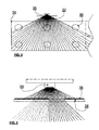
- Figure 2 illustrates schematically, with reference to the lighting arrangement shown in Figure 1 , the left-hand half-portion of the number plate as projected on a vertical plane 34 passing through the LED 26 and extending orthogonally to the running direction of the motor-vehicle.
- the circles 36 represent the luminance detection or measurement areas provided for by the European standard regulations (ECE).
- ECE European standard regulations
- the rays of the light beam 32 are those emitted by the LED 26 and lie on said plane 34.
- the measurement areas situated at the sides, i.e. more laterally, and on the lower portion of the half-plate are the most critical ones as far as the distribution of the light over the plate is concerned, since they are the farthest ones from the light source.
- the middle light rays i.e. the rays lying closer to the optical axis of the LED, have a higher intensity than those lying at the sides.
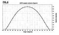
- Figure 6 represents a section of the spatial distribution of the relative luminous intensity of a LED versus the angular aperture. It can most clearly be noticed that a maximum in light intensity occur in connection with, i.e. at a zero angular aperture (optical axis), whereas light intensity then decreases as the inclination of the light rays increases.
- the angular aperture of a LED is defined as the sum of the two angles, which a light intensity amounting to 50% of the maximum value corresponds to, i.e. 60° in this particular case.
- the diffusion of the light emitted by the LED of course extends, i.e. continues - albeit with a gradually decreasing intensity - even beyond such angles of 60°, thereby contributing to the illumination of the areas located at the sides of the plate (critical areas).
- this characteristic clearly shows how the light rays dispersing rearwards, i.e. on the rear side of the motor-vehicle are provided with less energy than those on which there acts a lens that is applied so as to re-distribute light onto the lower portion of the number plate.
- a screening layer 38 in the lighting arrangement shown in Figure 3 there has been added - on a portion of the inner surface of the shielding member 28 - a screening layer 38, the functional purpose of which is to attenuate luminance in the middle region of the number plate lying closer to the light source, where there would otherwise concentrate a large amount of diffusing light, which is hardly capable of being subdued to any proper extent by the lens alone.
- the portion of area provided with said screening layer 38 is characterized by a particularly selected geometry preventing it from intersecting the rays of light directed towards the measurement circles in the lower row, as this shall be explained in greater detail further on.
- this screening layer 38 may be applied with any known method or technique, e.g.
- the layer may in the latter case be provided also on the outer side of the lens (i.e. the side facing away from the LED).
- Figure 4 is an axonometric representation of the inner surface of the shielding member 28 as partially provided with the above-mentioned screening layer 38.
- Figure 5 illustrates schematically, the left-hand half-portion of the number plate as projected on a vertical plane 34 passing through the LED 26 and extending orthogonally to the running direction of the motor-vehicle, wherein the elliptically shaped boundary of the luminance attenuation zone has been specially outlined in this Figure.
- Such partial screening brings about an attenuation effect that is not as clean-cut and sharply defined as this has been outlined, actually, since the LED 26 is not a spotlight-like source of light, but tends rather to emit light under a certain scattering of the related beam.
- this characteristic of the LED gives rise to a certain gradation or shading-off effect of the illuminated contour, which further contributes to an even illumination of the number plate of the motor-vehicle.
- a still more even distribution of the light on the number plate of the motor-vehicle is achieved through the use of a particular lens 40, which is preferably integrated in the transparent member 28 used to shield the LED 26, and which is effective in concentrating onto the number plate a greater number of rays that would otherwise be dispersed.
- the innovatory solution of the invention brings into effect a specific optical geometry, a section of which is known as planoconvex lens.
- the lens 40 has a cylindrical shape with a circular contour and, in a departure from the prior art, the convexity of the lens is in this case turned towards, i.e. facing the light source.
- the optical path of a ray of light along with the two light refraction points 1 and 2, which both faces of the planoconvex lens 40 contribute to.
- lens 40 has the above-mentioned planoconvex geometry in a section and, at the same time, the afore-cited cylindrical geometry in the section lying orthogonally thereto.
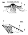
- Figure 9 is a schematic cross-sectional view of another embodiment representing a further improvement over the one illustrated in Figures 7 and 8 .
- the lens 40 and the shielding member 28, which are mutually integrated, are provided on the inner surface thereof with a partially screening member 38.
- the functional purpose of such partial screening provision is even in this case an attenuation of the luminance as indicated in Figure 5 .
- Figure 10 is an axonometric representation of the inner surface of the shielding member 28, as integrated with the lens 40 and with the above-mentioned partial screening provision 38 applied thereupon.
- Figure 11 is a schematic, vertical sectional view in a direction parallel to the running direction of the vehicle, of a third embodiment of the lighting arrangement according to the present invention, which represents again an improvement over the afore considered ones, and according to which a lens 42 features a convex contour with a variable curvature radius.
- the curvature radius is calculated under due consideration of a number of parameters. In this connection, particularly considered are such parameters as the configuration of the rear portion, i.e. the back of the motor-vehicle body, the distance of the light source to the number plate, and the inclination of the latter.
- both surfaces of the lens contribute to light refraction so as to obtain a correct and even distribution of the light rays all over the number plate.
- how - in view of achieving the desired effect-the variation of the curvature radius of the convex contour of the lens 42 is such as to effect a greater concentration of the light rays in the areas or zones lying far from the light source (lower portion of the number plate), and such light rays are also the most intense ones, since lying closer to the optical axis of the LED.
- the curvilinear contour of the lens 42 can be noticed to feature a variable curvature radius that is preferably wider in a first portion and narrower in a second portion thereof, as shown in the axonometric representation of Figure 12 when moving in the left-to-right direction.
- Figure 13 is a schematic cross-sectional view of an embodiment, which represents again a still further improvement over those illustrated in Figures 11 and 12 .
- the lens 42 and the shielding member 28, in a mutually integrated construction, are provided on the inner surface thereof with a screening member 38 that does not extend to cover the entire surface.
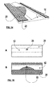
- Figure 14 is an axonometric representation of the inner surface of the shielding member 28, as integrated with the lens 42 featuring a variable-radius contour, and provided the partial screen 38. Even in this case, the functional purpose of such partial screening provision is attenuating the luminance in the way as indicated in Figure 5 .
- Figure 15 is a schematic view of the lighting arrangement as viewed from a point situated on the number plate, in the two embodiments thereof illustrated in Figure 11 and in Figure 13 , respectively.
- the screening is effective not only in conferring a particular aesthetically appealing quality to the lighting arrangement itself, but also in showing off a peculiar advantage of the present invention, i.e. the advantage deriving from the fact that, as compared with the usual size requirements of prior-art solutions in general, a marked reduction is in this case obtained in the size of the surface required for the passage of the light needed to adequately illuminate the number plate of a motor-vehicle.
- This reduction in the surface may then add to another kind of reduction, i.e. the reduction n in volume obtained through the use of a LED, to constitute a potentially innovatory feature as compared with the volume and space requirements usually connected to prior-art solutions.
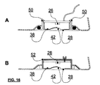
- Illustrated in Figure 16(A) is a single transparent member (incl. optical system 28, 42 and screening provision 38) supporting - through proper snap-fitting attachments 50 - the printed-circuit board carrying the LED 26 along with the related electronic components and wiring; the assembly (i.e. transparent member + circuit) can be mounted to a water-tight, i.e. appropriately sealed component part of the body of the motor-vehicle, such as the bonnet, the hatchback or related opening systems, under utilization of an appropriate gasket at the mounting interface to protect against water penetration.
- a water-tight i.e. appropriately sealed component part of the body of the motor-vehicle, such as the bonnet, the hatchback or related opening systems
- FIG. 16(B) Shown in Figure 16(B) is on the contrary the case represented by a small-sized module comprised of the transparent member (with related optical system 28, 42 and screening provision 38) joined to a box 52 acting as a container for the circuit and the connections with the vehicle-side electric system.
- the two plastic parts may be joined together by welding, bonding or other techniques capable of ensuring a proper sealing effect, i.e. water-tightness.
- Connection with the vehicle's electric system can on the other hand be provided through an appropriate conformation of the box for the required connector to be integrally formed there, with the related contacts already attached to the circuit. With such conformation thereof, the assembly can then be mounted to the bumper or other similar open, i.e. exposed and unsealed component part of the vehicle's body, since the small-sized module is water-tight by itself.
- Figure 17(C) illustrates a small-sized module similar to the above-described one, wherein the sole difference lies in the transparent member 28 provided as a bimaterial multilayered laminate, wherein the opaque and compressible layer 38 doubles as screening provision and sealing gasket at the same time.
- This kind of embodiment offers clear advantages of both a cost-related and a quality-related nature connected with the manufacturing process used for the part, and is further adapted to be applied to both sealed and non-sealed parts of the vehicle's body.
- Figure 17 (D) finally illustrates a small-sized module formed of the transparent member 28 made as a rigid multi-layer (transparent/opaque) bimaterial composite in such a structure as to integrally form the walls of the containment box; in this way, it is sufficient for a simple planar member supporting the circuit, and allowing the connection wires to exit, to be joined thereto, e.g. by welding or some other known technique. Even this embodiment allows for application to both sealed and non-sealed parts of the vehicle's body.
Landscapes
- Engineering & Computer Science (AREA)
- Mechanical Engineering (AREA)
- General Engineering & Computer Science (AREA)
- Non-Portable Lighting Devices Or Systems Thereof (AREA)
- Lighting Device Outwards From Vehicle And Optical Signal (AREA)
- Arrangements Of Lighting Devices For Vehicle Interiors, Mounting And Supporting Thereof, Circuits Therefore (AREA)
- Vehicle Waterproofing, Decoration, And Sanitation Devices (AREA)
Applications Claiming Priority (1)
| Application Number | Priority Date | Filing Date | Title |
|---|---|---|---|
| IT000022A ITPN20070022A1 (it) | 2007-04-17 | 2007-04-17 | "dispositivo per illuminare la targa di un autoveicolo" |
Publications (3)
| Publication Number | Publication Date |
|---|---|
| EP1982866A2 true EP1982866A2 (de) | 2008-10-22 |
| EP1982866A3 EP1982866A3 (de) | 2009-01-21 |
| EP1982866B1 EP1982866B1 (de) | 2011-06-15 |
Family
ID=39591705
Family Applications (1)
| Application Number | Title | Priority Date | Filing Date |
|---|---|---|---|
| EP08154591A Active EP1982866B1 (de) | 2007-04-17 | 2008-04-16 | Beleuchtungsanordnung für die Beleuchtung des Nummernschildes eines Motorfahrzeugs |
Country Status (3)
| Country | Link |
|---|---|
| EP (1) | EP1982866B1 (de) |
| AT (1) | ATE512831T1 (de) |
| IT (1) | ITPN20070022A1 (de) |
Cited By (6)
| Publication number | Priority date | Publication date | Assignee | Title |
|---|---|---|---|---|
| EP2088031A3 (de) * | 2008-02-06 | 2009-12-16 | Koito Manufacturing Co., Ltd | Kennzeichenleuchte |
| EP2660644A1 (de) * | 2012-05-02 | 2013-11-06 | Cedes Safety & Automation AG | Linsenträger und optisches Modul für einen Lichtvorhang und Herstellungsverfahren |
| ITPN20120076A1 (it) * | 2012-12-20 | 2014-06-21 | Sole Spa | Dispositivo diffusore perfezionato per illuminare la targa di un autoveicolo e relativo metodo di realizzazione |
| WO2014161675A1 (de) * | 2013-04-05 | 2014-10-09 | Audi Ag | Beleuchtungseinrichtung für ein hinteres kennzeichenschild eines kraftfahrzeugs |
| CN110220161A (zh) * | 2018-03-01 | 2019-09-10 | 法雷奥市光(中国)车灯有限公司 | 配光装置、用于机动车辆的牌照灯以及机动车辆 |
| CN113137586A (zh) * | 2020-01-17 | 2021-07-20 | 株式会社东海理化电机制作所 | 透镜以及牌照灯 |
Citations (1)
| Publication number | Priority date | Publication date | Assignee | Title |
|---|---|---|---|---|
| EP1264732A2 (de) | 2001-06-08 | 2002-12-11 | Plastal S.p.A. | Vorrichtung zur Ausleuchtung des Kennzeichenschilds eines Kraftfahrzeugs |
Family Cites Families (3)
| Publication number | Priority date | Publication date | Assignee | Title |
|---|---|---|---|---|
| JP4437707B2 (ja) * | 2004-06-24 | 2010-03-24 | 株式会社小糸製作所 | ライセンスプレートの照明装置 |
| JP2007030592A (ja) * | 2005-07-25 | 2007-02-08 | Yamaha Motor Co Ltd | 車両用ライト装置及び該ライト装置を備えた自動二輪車 |
| JP2007039920A (ja) * | 2005-08-01 | 2007-02-15 | Toyota Motor Corp | 車両用ハンドル装置 |
-
2007
- 2007-04-17 IT IT000022A patent/ITPN20070022A1/it unknown
-
2008
- 2008-04-16 EP EP08154591A patent/EP1982866B1/de active Active
- 2008-04-16 AT AT08154591T patent/ATE512831T1/de not_active IP Right Cessation
Patent Citations (1)
| Publication number | Priority date | Publication date | Assignee | Title |
|---|---|---|---|---|
| EP1264732A2 (de) | 2001-06-08 | 2002-12-11 | Plastal S.p.A. | Vorrichtung zur Ausleuchtung des Kennzeichenschilds eines Kraftfahrzeugs |
Cited By (10)
| Publication number | Priority date | Publication date | Assignee | Title |
|---|---|---|---|---|
| EP2088031A3 (de) * | 2008-02-06 | 2009-12-16 | Koito Manufacturing Co., Ltd | Kennzeichenleuchte |
| EP2660644A1 (de) * | 2012-05-02 | 2013-11-06 | Cedes Safety & Automation AG | Linsenträger und optisches Modul für einen Lichtvorhang und Herstellungsverfahren |
| CN103383469A (zh) * | 2012-05-02 | 2013-11-06 | 赛德斯安全与自动化公司 | 用于光幕的透镜架和光学模块及加工方法 |
| US9274343B2 (en) | 2012-05-02 | 2016-03-01 | Rockwell Automation Safety Ag | Lens carrier and optical module for a light curtain and fabrication method |
| CN103383469B (zh) * | 2012-05-02 | 2016-12-07 | 洛克威尔自动控制安全公司 | 用于光幕的透镜架和光学模块及加工方法 |
| ITPN20120076A1 (it) * | 2012-12-20 | 2014-06-21 | Sole Spa | Dispositivo diffusore perfezionato per illuminare la targa di un autoveicolo e relativo metodo di realizzazione |
| WO2014161675A1 (de) * | 2013-04-05 | 2014-10-09 | Audi Ag | Beleuchtungseinrichtung für ein hinteres kennzeichenschild eines kraftfahrzeugs |
| CN110220161A (zh) * | 2018-03-01 | 2019-09-10 | 法雷奥市光(中国)车灯有限公司 | 配光装置、用于机动车辆的牌照灯以及机动车辆 |
| CN113137586A (zh) * | 2020-01-17 | 2021-07-20 | 株式会社东海理化电机制作所 | 透镜以及牌照灯 |
| CN113137586B (zh) * | 2020-01-17 | 2023-07-07 | 株式会社东海理化电机制作所 | 透镜以及牌照灯 |
Also Published As
| Publication number | Publication date |
|---|---|
| ATE512831T1 (de) | 2011-07-15 |
| EP1982866A3 (de) | 2009-01-21 |
| EP1982866B1 (de) | 2011-06-15 |
| ITPN20070022A1 (it) | 2008-10-18 |
Similar Documents
| Publication | Publication Date | Title |
|---|---|---|
| US7699511B2 (en) | Door mirror with turn lamp | |
| US7134775B2 (en) | Vehicular headlamp and light-emitting module therefor | |
| US7883249B2 (en) | Lighting device for vehicle | |
| JP6675437B2 (ja) | 車用二重機能照明モジュール及び車用二重機能照明セット/vehicle dual−function lighting module and dual−function lighting set | |
| EP1982866B1 (de) | Beleuchtungsanordnung für die Beleuchtung des Nummernschildes eines Motorfahrzeugs | |
| JP4798784B2 (ja) | 車両用灯具 | |
| KR20090086173A (ko) | 번호판 램프 | |
| JP6609135B2 (ja) | 車両用リアコンビネーションランプ | |
| JP7458238B2 (ja) | 車両用灯具 | |
| US10718482B2 (en) | Vehicle lamp with plate like lens having front and rear lens cuts | |
| JP2018195467A (ja) | 車両用灯具 | |
| CN112146057A (zh) | 车辆用灯具 | |
| JP2020098726A (ja) | 鞍乗型車両用灯具 | |
| EP3838564B1 (de) | Fahrzeugbeleuchtungshalterung | |
| CN105202439A (zh) | 车辆用灯具 | |
| JP6793494B2 (ja) | 車両用灯具 | |
| WO2023210678A1 (ja) | 車両用灯具 | |
| JP2021190342A (ja) | 車両用灯具 | |
| JP6320110B2 (ja) | ライセンスランプを備えた車両用灯具 | |
| CN111412433B (zh) | 机动车位置灯结构及机动车 | |
| JP6920015B2 (ja) | 車両用灯具 | |
| SK131999A3 (en) | Vehicle light | |
| CZ308337B6 (cs) | Sestava pro osvětlení plošného emblému s nízkou zástavbovou hloubkou | |
| JP2018195466A (ja) | 車両用灯具 | |
| JP2022026943A (ja) | 自動運転標識灯 |
Legal Events
| Date | Code | Title | Description |
|---|---|---|---|
| PUAI | Public reference made under article 153(3) epc to a published international application that has entered the european phase |
Free format text: ORIGINAL CODE: 0009012 |
|
| AK | Designated contracting states |
Kind code of ref document: A2 Designated state(s): AT BE BG CH CY CZ DE DK EE ES FI FR GB GR HR HU IE IS IT LI LT LU LV MC MT NL NO PL PT RO SE SI SK TR |
|
| AX | Request for extension of the european patent |
Extension state: AL BA MK RS |
|
| PUAL | Search report despatched |
Free format text: ORIGINAL CODE: 0009013 |
|
| AK | Designated contracting states |
Kind code of ref document: A3 Designated state(s): AT BE BG CH CY CZ DE DK EE ES FI FR GB GR HR HU IE IS IT LI LT LU LV MC MT NL NO PL PT RO SE SI SK TR |
|
| AX | Request for extension of the european patent |
Extension state: AL BA MK RS |
|
| 17P | Request for examination filed |
Effective date: 20090717 |
|
| 17Q | First examination report despatched |
Effective date: 20090821 |
|
| AKX | Designation fees paid |
Designated state(s): AT BE BG CH CY CZ DE DK EE ES FI FR GB GR HR HU IE IS IT LI LT LU LV MC MT NL NO PL PT RO SE SI SK TR |
|
| GRAP | Despatch of communication of intention to grant a patent |
Free format text: ORIGINAL CODE: EPIDOSNIGR1 |
|
| GRAS | Grant fee paid |
Free format text: ORIGINAL CODE: EPIDOSNIGR3 |
|
| GRAA | (expected) grant |
Free format text: ORIGINAL CODE: 0009210 |
|
| AK | Designated contracting states |
Kind code of ref document: B1 Designated state(s): AT BE BG CH CY CZ DE DK EE ES FI FR GB GR HR HU IE IS IT LI LT LU LV MC MT NL NO PL PT RO SE SI SK TR |
|
| REG | Reference to a national code |
Ref country code: GB Ref legal event code: FG4D Ref country code: CH Ref legal event code: EP |
|
| REG | Reference to a national code |
Ref country code: IE Ref legal event code: FG4D |
|
| REG | Reference to a national code |
Ref country code: DE Ref legal event code: R096 Ref document number: 602008007564 Country of ref document: DE Effective date: 20110804 |
|
| REG | Reference to a national code |
Ref country code: SE Ref legal event code: TRGR |
|
| REG | Reference to a national code |
Ref country code: NL Ref legal event code: VDEP Effective date: 20110615 |
|
| PG25 | Lapsed in a contracting state [announced via postgrant information from national office to epo] |
Ref country code: HR Free format text: LAPSE BECAUSE OF FAILURE TO SUBMIT A TRANSLATION OF THE DESCRIPTION OR TO PAY THE FEE WITHIN THE PRESCRIBED TIME-LIMIT Effective date: 20110615 Ref country code: LT Free format text: LAPSE BECAUSE OF FAILURE TO SUBMIT A TRANSLATION OF THE DESCRIPTION OR TO PAY THE FEE WITHIN THE PRESCRIBED TIME-LIMIT Effective date: 20110615 Ref country code: NO Free format text: LAPSE BECAUSE OF FAILURE TO SUBMIT A TRANSLATION OF THE DESCRIPTION OR TO PAY THE FEE WITHIN THE PRESCRIBED TIME-LIMIT Effective date: 20110915 |
|
| PG25 | Lapsed in a contracting state [announced via postgrant information from national office to epo] |
Ref country code: CY Free format text: LAPSE BECAUSE OF FAILURE TO SUBMIT A TRANSLATION OF THE DESCRIPTION OR TO PAY THE FEE WITHIN THE PRESCRIBED TIME-LIMIT Effective date: 20110615 Ref country code: AT Free format text: LAPSE BECAUSE OF FAILURE TO SUBMIT A TRANSLATION OF THE DESCRIPTION OR TO PAY THE FEE WITHIN THE PRESCRIBED TIME-LIMIT Effective date: 20110615 Ref country code: FI Free format text: LAPSE BECAUSE OF FAILURE TO SUBMIT A TRANSLATION OF THE DESCRIPTION OR TO PAY THE FEE WITHIN THE PRESCRIBED TIME-LIMIT Effective date: 20110615 Ref country code: LV Free format text: LAPSE BECAUSE OF FAILURE TO SUBMIT A TRANSLATION OF THE DESCRIPTION OR TO PAY THE FEE WITHIN THE PRESCRIBED TIME-LIMIT Effective date: 20110615 Ref country code: GR Free format text: LAPSE BECAUSE OF FAILURE TO SUBMIT A TRANSLATION OF THE DESCRIPTION OR TO PAY THE FEE WITHIN THE PRESCRIBED TIME-LIMIT Effective date: 20110916 Ref country code: SI Free format text: LAPSE BECAUSE OF FAILURE TO SUBMIT A TRANSLATION OF THE DESCRIPTION OR TO PAY THE FEE WITHIN THE PRESCRIBED TIME-LIMIT Effective date: 20110615 |
|
| PG25 | Lapsed in a contracting state [announced via postgrant information from national office to epo] |
Ref country code: NL Free format text: LAPSE BECAUSE OF FAILURE TO SUBMIT A TRANSLATION OF THE DESCRIPTION OR TO PAY THE FEE WITHIN THE PRESCRIBED TIME-LIMIT Effective date: 20110615 Ref country code: BE Free format text: LAPSE BECAUSE OF FAILURE TO SUBMIT A TRANSLATION OF THE DESCRIPTION OR TO PAY THE FEE WITHIN THE PRESCRIBED TIME-LIMIT Effective date: 20110615 |
|
| PG25 | Lapsed in a contracting state [announced via postgrant information from national office to epo] |
Ref country code: PT Free format text: LAPSE BECAUSE OF FAILURE TO SUBMIT A TRANSLATION OF THE DESCRIPTION OR TO PAY THE FEE WITHIN THE PRESCRIBED TIME-LIMIT Effective date: 20111017 Ref country code: CZ Free format text: LAPSE BECAUSE OF FAILURE TO SUBMIT A TRANSLATION OF THE DESCRIPTION OR TO PAY THE FEE WITHIN THE PRESCRIBED TIME-LIMIT Effective date: 20110615 Ref country code: EE Free format text: LAPSE BECAUSE OF FAILURE TO SUBMIT A TRANSLATION OF THE DESCRIPTION OR TO PAY THE FEE WITHIN THE PRESCRIBED TIME-LIMIT Effective date: 20110615 Ref country code: IS Free format text: LAPSE BECAUSE OF FAILURE TO SUBMIT A TRANSLATION OF THE DESCRIPTION OR TO PAY THE FEE WITHIN THE PRESCRIBED TIME-LIMIT Effective date: 20111015 |
|
| PG25 | Lapsed in a contracting state [announced via postgrant information from national office to epo] |
Ref country code: RO Free format text: LAPSE BECAUSE OF FAILURE TO SUBMIT A TRANSLATION OF THE DESCRIPTION OR TO PAY THE FEE WITHIN THE PRESCRIBED TIME-LIMIT Effective date: 20110615 Ref country code: PL Free format text: LAPSE BECAUSE OF FAILURE TO SUBMIT A TRANSLATION OF THE DESCRIPTION OR TO PAY THE FEE WITHIN THE PRESCRIBED TIME-LIMIT Effective date: 20110615 Ref country code: SK Free format text: LAPSE BECAUSE OF FAILURE TO SUBMIT A TRANSLATION OF THE DESCRIPTION OR TO PAY THE FEE WITHIN THE PRESCRIBED TIME-LIMIT Effective date: 20110615 |
|
| PLBE | No opposition filed within time limit |
Free format text: ORIGINAL CODE: 0009261 |
|
| STAA | Information on the status of an ep patent application or granted ep patent |
Free format text: STATUS: NO OPPOSITION FILED WITHIN TIME LIMIT |
|
| 26N | No opposition filed |
Effective date: 20120316 |
|
| PG25 | Lapsed in a contracting state [announced via postgrant information from national office to epo] |
Ref country code: DK Free format text: LAPSE BECAUSE OF FAILURE TO SUBMIT A TRANSLATION OF THE DESCRIPTION OR TO PAY THE FEE WITHIN THE PRESCRIBED TIME-LIMIT Effective date: 20110615 |
|
| REG | Reference to a national code |
Ref country code: DE Ref legal event code: R097 Ref document number: 602008007564 Country of ref document: DE Effective date: 20120316 |
|
| PG25 | Lapsed in a contracting state [announced via postgrant information from national office to epo] |
Ref country code: MC Free format text: LAPSE BECAUSE OF NON-PAYMENT OF DUE FEES Effective date: 20120430 |
|
| REG | Reference to a national code |
Ref country code: CH Ref legal event code: PL |
|
| REG | Reference to a national code |
Ref country code: IE Ref legal event code: MM4A |
|
| PG25 | Lapsed in a contracting state [announced via postgrant information from national office to epo] |
Ref country code: IE Free format text: LAPSE BECAUSE OF NON-PAYMENT OF DUE FEES Effective date: 20120416 Ref country code: CH Free format text: LAPSE BECAUSE OF NON-PAYMENT OF DUE FEES Effective date: 20120430 Ref country code: LI Free format text: LAPSE BECAUSE OF NON-PAYMENT OF DUE FEES Effective date: 20120430 |
|
| PG25 | Lapsed in a contracting state [announced via postgrant information from national office to epo] |
Ref country code: ES Free format text: LAPSE BECAUSE OF FAILURE TO SUBMIT A TRANSLATION OF THE DESCRIPTION OR TO PAY THE FEE WITHIN THE PRESCRIBED TIME-LIMIT Effective date: 20110926 |
|
| PG25 | Lapsed in a contracting state [announced via postgrant information from national office to epo] |
Ref country code: BG Free format text: LAPSE BECAUSE OF FAILURE TO SUBMIT A TRANSLATION OF THE DESCRIPTION OR TO PAY THE FEE WITHIN THE PRESCRIBED TIME-LIMIT Effective date: 20110915 |
|
| PG25 | Lapsed in a contracting state [announced via postgrant information from national office to epo] |
Ref country code: MT Free format text: LAPSE BECAUSE OF FAILURE TO SUBMIT A TRANSLATION OF THE DESCRIPTION OR TO PAY THE FEE WITHIN THE PRESCRIBED TIME-LIMIT Effective date: 20110615 |
|
| PG25 | Lapsed in a contracting state [announced via postgrant information from national office to epo] |
Ref country code: TR Free format text: LAPSE BECAUSE OF FAILURE TO SUBMIT A TRANSLATION OF THE DESCRIPTION OR TO PAY THE FEE WITHIN THE PRESCRIBED TIME-LIMIT Effective date: 20110615 |
|
| PG25 | Lapsed in a contracting state [announced via postgrant information from national office to epo] |
Ref country code: LU Free format text: LAPSE BECAUSE OF NON-PAYMENT OF DUE FEES Effective date: 20120416 |
|
| PG25 | Lapsed in a contracting state [announced via postgrant information from national office to epo] |
Ref country code: HU Free format text: LAPSE BECAUSE OF FAILURE TO SUBMIT A TRANSLATION OF THE DESCRIPTION OR TO PAY THE FEE WITHIN THE PRESCRIBED TIME-LIMIT Effective date: 20080416 |
|
| REG | Reference to a national code |
Ref country code: FR Ref legal event code: PLFP Year of fee payment: 9 |
|
| REG | Reference to a national code |
Ref country code: FR Ref legal event code: PLFP Year of fee payment: 10 |
|
| REG | Reference to a national code |
Ref country code: FR Ref legal event code: PLFP Year of fee payment: 11 |
|
| PGFP | Annual fee paid to national office [announced via postgrant information from national office to epo] |
Ref country code: DE Payment date: 20250422 Year of fee payment: 18 |
|
| PGFP | Annual fee paid to national office [announced via postgrant information from national office to epo] |
Ref country code: GB Payment date: 20250418 Year of fee payment: 18 |
|
| PGFP | Annual fee paid to national office [announced via postgrant information from national office to epo] |
Ref country code: FR Payment date: 20250424 Year of fee payment: 18 |
|
| PGFP | Annual fee paid to national office [announced via postgrant information from national office to epo] |
Ref country code: SE Payment date: 20250429 Year of fee payment: 18 |
|
| PGFP | Annual fee paid to national office [announced via postgrant information from national office to epo] |
Ref country code: IT Payment date: 20260313 Year of fee payment: 19 |