EP2660644A1 - Linsenträger und optisches Modul für einen Lichtvorhang und Herstellungsverfahren - Google Patents
Linsenträger und optisches Modul für einen Lichtvorhang und Herstellungsverfahren Download PDFInfo
- Publication number
- EP2660644A1 EP2660644A1 EP12166435.3A EP12166435A EP2660644A1 EP 2660644 A1 EP2660644 A1 EP 2660644A1 EP 12166435 A EP12166435 A EP 12166435A EP 2660644 A1 EP2660644 A1 EP 2660644A1
- Authority
- EP
- European Patent Office
- Prior art keywords
- lens
- optical
- lens carrier
- carrier
- module body
- Prior art date
- Legal status (The legal status is an assumption and is not a legal conclusion. Google has not performed a legal analysis and makes no representation as to the accuracy of the status listed.)
- Granted
Links
Images



Classifications
-
- G—PHYSICS
- G02—OPTICS
- G02B—OPTICAL ELEMENTS, SYSTEMS OR APPARATUS
- G02B27/00—Optical systems or apparatus not provided for by any of the groups G02B1/00 - G02B26/00, G02B30/00
- G02B27/09—Beam shaping, e.g. changing the cross-sectional area, not otherwise provided for
- G02B27/0938—Using specific optical elements
- G02B27/095—Refractive optical elements
- G02B27/0955—Lenses
- G02B27/0961—Lens arrays
-
- G—PHYSICS
- G01—MEASURING; TESTING
- G01V—GEOPHYSICS; GRAVITATIONAL MEASUREMENTS; DETECTING MASSES OR OBJECTS; TAGS
- G01V8/00—Prospecting or detecting by optical means
- G01V8/10—Detecting, e.g. by using light barriers
-
- Y—GENERAL TAGGING OF NEW TECHNOLOGICAL DEVELOPMENTS; GENERAL TAGGING OF CROSS-SECTIONAL TECHNOLOGIES SPANNING OVER SEVERAL SECTIONS OF THE IPC; TECHNICAL SUBJECTS COVERED BY FORMER USPC CROSS-REFERENCE ART COLLECTIONS [XRACs] AND DIGESTS
- Y10—TECHNICAL SUBJECTS COVERED BY FORMER USPC
- Y10T—TECHNICAL SUBJECTS COVERED BY FORMER US CLASSIFICATION
- Y10T29/00—Metal working
- Y10T29/49—Method of mechanical manufacture
- Y10T29/49826—Assembling or joining
Definitions
- the present invention relates to industrial light curtains which monitor a protective or surveillance field and in particular relates to optical modules that can be used for such a light curtain.
- Light curtains which are formed by one or more radiation beams are usually also referred to as light grids or light barriers.
- light curtains detect the movement or intrusion of objects into guarded zones and may provide protection for human operators who are working with machines or other industrial equipment.
- Some light curtain systems are designed to control and monitor industrial automation processes and are in particular used for verifying assembly processes, counting objects, confirming an ejection process, recognize leading edges of transported goods, recognizing irregular shapes and a lot of other applications.
- Safety light curtains employing infrared or visible light beams are used to provide operator safety in a variety of industrial applications.
- the operator protection around machinery such as punch presses, guillotines, molding machines, automatic assembly equipment, coil winding machinery, robot operation, casting operations and the like can be ensured by using light curtains.
- Conventional light curtains typically employ light emitting diodes (LED) mounting at spaced positions along a transmitter bar at one side of the guarded zone, and phototransistors (PT), photodiodes or photo receivers mounted along a receiver bar at the opposite side of the zone.
- the LEDs transmit modulated infrared light beams along separate parallel channels to the PTs at the receiver bar. If one or more beams are blocked from penetration by an opaque object, such as the operator's arm, the control circuit shuts down the machine, prevents the machine from cycling, or otherwise safeguards the area.
- such an interruption of the beam can also be used for counting objects or verifying the entrance of goods through defined areas.
- light curtains comprise two optical units, often called bars, sticks or strips, which are formed as to different constructional units, one of the optical units having the function of an emitter and one of a receiver.
- This dedicated architecture of an emitter and receiver has several drawbacks, for instance the fact that the fabrication costs are high, because each type of optical unit has to be fabricated differently. Consequently, there exist concepts that use an architecture, wherein each optical unit has light emitting elements and light receiving elements at the same time.
- optical units With providing the optical units with identical optical modules, which can operate as a receiver as well as a transmitter, and by additionally providing plug-in units, which differentiate the particular optical unit in its function as the emitter with, for instance, a test input, or as the receiver with, for instance, the output signal switching devices (OSSD), a particularly cost-effective way of fabricating optical units for a large scale production can be achieved.
- plug-in units which differentiate the particular optical unit in its function as the emitter with, for instance, a test input, or as the receiver with, for instance, the output signal switching devices (OSSD)
- the problem underlying the present invention therefore is to provide an optical module and a fabrication method, whereby a particular cost-effective and reliable fabrication and adjustment of the optical components can be achieved.
- This problem is solved by the subject matter of the independent claims.
- Advantageous improvements are the subject matter of the dependent claims.
- the present invention is based on the idea to use an improved lens carrier in an optical module for a light curtain.
- the lens carrier has at least one lens for focusing a radiation beam forming the light curtain and a lens mask having at least one opening for shaping the radiation beam to have a predetermined aperture.
- this lens carrier is formed by overmolding the lens mask with a transparent material.
- the lens carrier and at least one lens are fabricated as one integral part.
- all the lenses can be fabricated and aligned with respect to each other in one tightly toleranced overmolding step.
- the thermal expansion of the composite lens carrier consisting of a metal lens mask overmolded with a plastic lens material is determined by the characteristic values of the metal sheet. These values, however, are compatible with the printed circuit board on the one hand and surrounding metal profiles on the other hand. Thus, the robustness and reliability of the assembled optical module can be improved even for applications in a rough environment with considerable temperature differences.
- plano-convex or biconvex lenses can be formed on the lens carrier.
- Fresnel lens can be fabricated which has the advantage of being much thinner than the plano-convex or biconvex lenses.
- the lens carrier according to the present invention can also be provided with additional optical or mechanical functional elements.
- optical functional elements can for instance be waveguides for optical indicator means, parts of laser alignment systems or the like.
- the mechanical functional elements may for instance comprise mounting means, additional mechanical features, which allow a disassembly of the fully mounted optical module from its housing or the like.
- the tolerance chain can be kept short and therefore any additional optical or mechanical features are directly correlated with the position of the lenses and the lens mask.
- the transparent material which forms the lenses comprises polymethylmethacrylate (PMMA) or polycarbonate (PC). It is clear for a person skilled in the art, that all other transparent materials which have the required chemical and physical characteristics may of course also be used for fabricating a lens carrier according to the present invention. An overview over suitable materials can for instance be found in De Schipper, R. et al: "Kunststoffoptik", Optik & Photonik, pas 2006, Nr. 2, p. 47-49 .
- An optical module comprises an integrally formed lens carrier and a module body for mounting a radiation transmitter/receiver carrier comprising at least one transmitter and/or receiver for transmitting and/or receiving the radiation.
- the carrier will be formed by a printed circuit board (PCB).
- the module body and the lens carrier can be fabricated as one integral molded part.
- very low tolerances between the at least one lens and the module body can be achieved.
- the module body in most cases will represent the geometric reference for aligning the optical module during assembly.
- the tolerances between the optical axis of the lens and any surfaces to which the optical module is mounted can be kept low.
- the module body may comprise a stabilization element which is integrated into the module body.
- the mechanical stability can be enhanced and furthermore, the thermal expansion can be adapted to the characteristics of the lens carrier.
- a PCB is mounted to the module body, same has a very similar thermal expansion as the module, which is particularly important when LED chips are placed on the printed circuit board by means of a chip-on-board (COB) assembly technique.
- COB chip-on-board
- any other circuit carriers e. g. Molded Interconnect Device (MID) carriers, can also be used.
- MID carrier can firstly be fabricated together with the module body in the same molding step, and secondly provides the possibility of fabricating a three-dimensional circuit carrier structure.
- the module body itself could be an MID part where the electrically conductive leads and optoelectronic components are arranged directly on the module body. In this case, an additional circuit carrier for the optoelectronic components can be avoided.
- the stabilization element may furthermore form or be a part of an optical stop element comprising at least one cut-out for letting pass the radiation from/to the radiation transmitter and/or receiver.
- the stabilization element has to be fabricated from an opaque material, for instance from a stamped metal sheet.
- these sheets additionally provide an electromagnetic shielding for the underlying electronic components on the PCB.
- mechanical fixing means such as protrusions, snap-in hooks, snap-in notches, or the like.
- the dimensions of the cut-outs may also be defined by the overmolded plastic material in order to form a particularly tightly toleranced aperture.
- the optical module according to the present invention has an optical shielding element (also called beam separator in the following), which can be inserted as a part separate from the module body and the lens carrier.
- an optical shielding element also called beam separator in the following
- this part does not need any particularly accurate alignment, it can be fabricated as a cheap and simple part, which only has to fulfill the requirement of being formed from an opaque material.
- a method for fabricating an optical module according to the present invention includes fabricating a lens carrier by overmolding a lens mask with a transparent material and providing a module body, which is fabricated by overmolding the lens carrier.
- the lens mask is inserted into the tool which is then overmolded to form the lens carrier.
- the stabilization element may be positioned within the molding tool and the lens carrier and the stabilization element are then overmolded to form the integrated optical module.
- the beam separator cam be integrated into the module body or can be mounted in a direction along the optical axis of the radiation beam.
- module body and the lens carrier can also be fabricated in separate molding steps and subsequently be attached to each other.
- the optical shielding element is only inserted after removing the module body with the lens carrier from the molding tool by sliding in the optical shielding element in a direction across to the optical axis of the at least one lens.
- FIG. 1 shows in a perspective view an optical module 100 according to the present invention with a printed circuit board (PCB) 102 connected thereto.
- the optical module with the PCB 102 are to be mounted in an outer housing, a so-called profile (not shown in the figures).
- the combination of the optical unit 100 and the PCB 102 represents the functional unit for transmitting and/or receiving light which forms a light curtain for monitoring a desired surveillance area.
- a second, corresponding optical module with a printed circuit board is arranged opposing to the one shown in FIG. 1 .
- reflecting elements can of course be used.
- the PCB 102 carries the light-emitting and/or receiving elements and the required interconnection leads. If necessary, also integrated circuitry can be provided on one or both of the surfaces of the printed circuit board 102.
- the emitted radiation can in particular be visible light, in particular red light with a wavelength range of 620 nm to 750 nm.
- visible light optical units containing optical modules according to the present invention can be aligned when mounting same in the surveillance area by visual control of a human operator. In contrast to light curtains where infrared light is used for the emitters, such an alignment can be performed without additional costs and furthermore, the eye protection requirements can be fulfilled much more easily.
- the PCB 102 may carry an LED as a light emitting device or a photodiode as a light detecting element or may even carry combined transceiver element, as this is for instance proposed in the European patent application EP 11 162 263.5 "Modular light curtain and optical unit for a light curtain".
- the optical module comprises a lens carrier 104, which combines a plurality of lenses 106 as one integral unit.
- a module body 108 serves for mounting the PCB 102 and furthermore carries a stop element having openings for letting pass the radiation between the PCB 102 and the lens 106. This will become more obvious when further looking at FIG. 2 .
- Mounting and alignment means 112 are provided for adjusting the position of the optical module with the PCB 102 in a profile (not shown in the figures).
- a light curtain normally has several beams that are placed closely together, whereas a light grid consists of only one, two, three or four light beams. The beams are closest on a light curtain that is used for finger detection, then the resolution has to be 14 mm. Light curtain beams are at their widest spacing when used for thigh detection (90 mm resolution). Accordingly, hand resolution is defined at 30 mm.
- the optical module 100 further comprises a beam separating element 114.
- the beam separating element 114 is fabricated from an opaque plastic material and separates the space between the lens 106 and the LED or photodiode on the PCB 102 into individual chambers.
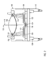
- FIG. 2 shows a schematic sectional view of the arrangement of FIG. 1 .
- a light receiving and/or a light emitting element 116 is mounted on the PCB 102 .
- This optical sender and/or receiver 116 defines a first optical axis 118.
- the centre of the lens 106 defines a second optical axis 120.
- These two optical axes ideally coincide, but in any case have to be as close as possible to each other.
- the lens carrier 104 is formed by overmolding a lens mask 122 with a transparent plastic material.
- the transparent material may for instance comprise polymethylmethacrylate (PMMA) or polycarbonate (PC).
- the lens mask 122 has openings corresponding to the location of each lens 106, which are formed to shape the radiation emitted by a light-emitting element 116 into a particular beam shape corresponding to the required resolution of the light curtain.
- PMMA polymethylmethacrylate
- PC polycarbonate
- an optical stop element 110 with a small opening 124 is provided.
- This optical stop element can also be an integral part of the module body 108.
- a preferably metallic stabilization element 126 is integrated within the optical stop element 124.
- the beam separating element 114 defines different chambers under each lens 106 for optically shielding the individual beams from each other.
- the lens mask 122 which is shown in more detail in figures 3 and 4 , is fabricated from a stamped and bent metal sheet.
- the lens mask is aligned in a molding tool and overmolded with a transparent plastic material to form the lens carrier 104 with a plurality of lenses 106.
- the lens carrier is not removed from the molding tool, but in a next step, the stabilization element 126, which will be explained in more detail referring to FIG. 5 , is aligned in the molding tool.
- the module body 108 is fabricated.
- the used material may for instance be Polybutyleneterephthalate (PBT).
- the module body By fabricating the module body as one integral molded part with the lens carrier very tight tolerances can be achieved, because the elements which define the later mounted position of the PCB 102 are fabricated within the same tool as the lens 106. According to the embodiment shown in FIG. 2 , a plurality of mounting projections 128 interact with corresponding openings in the PCB 102 for mounting same at the module body 108.
- module body 108 can also be formed as a separate component which is joined with the lens carrier 104 by any known mechanical means.
- a further advantageous feature of the present invention is the fact that by integrating metal structures as the lens mask 122 and the stabilization element 126, the thermal expansion of the lens carrier 104 and the optical stop element 124 are much closer to the thermal expansion of the PCB 102 than a pure plastic material would be. Consequently, even under significantly differing temperature conditions, the alignment between the position of the light receiving and/or emitting elements 116, the openings of the optical stop element and the optical axes of the lenses 106 can always be maintained.
- a further advantage of using an electrically conductive lens mask and, in particular, stabilization element 126 is the additional effect of an electromagnetic shielding towards the PCB 102.
- FIGs. 3 and 4 show two particular embodiments of the lens mask 122 before same is overmolded with the transparent lens material.
- FIG. 3 shows a form of the masking opening 130, which can be used for optical modules that allow the application in an environment where a hand resolution is required.
- the light passing through two or more openings 130 is combined to form one radiation beam and a larger distance is left between one beam and the next.
- FIG. 4 shows a lens mask 122 that is suitable for shaping closely adjacent radiation beams for a finger resolution.
- the openings in the lens mask 130 have the shape of two circular arcs forming an eye shaped, biconvex outline.
- the lens mask 122 further comprises additional openings and protrusions which can serve purposes as mounting an alignment laser or indication LEDs or the like.
- the lens mask 122 is fabricated by stamping and bending a metal sheet, as this is known for a person skilled in the art.
- the optical stop element 110 which is formed integrally with the module body 108, also contains an integrated metal part, the stabilization element 126 shown in FIG. 5 .
- the stabilization element 126 is fabricated in a similar process as the lens mask 122 by stamping and bending a metal sheet.
- cut-outs 124 are provided, which in the finally mounted state correspond to the positions where the light receiving and/or emitting elements are located on the printed circuit board 102.
- the stabilization element 126 has reinforcement elements 132 that extend along a sidewall of the module body for adding mechanical stability thereto.
- the mounting and alignment means 112 can be reinforced by such a reinforcement element 132. Due to its electrical conductivity, the stabilization element 126 also provides electromagnetic shielding for the adjacent PCB components.
- FIG. 6 shows how the plastic material forming the module body 108 is cast around the stabilization element 126.
- the lens carrier which may be overmolded together with the stabilization element 126 in the same fabrication step is not shown.
- FIG. 7 shows the complete part after overmolding the lens carrier 104 and stabilization element 126 to form the module body 108. This is the state of the part where it is removed from the molding tool.
- the beam separating element 114 is inserted in a direction 134 across to the optical axis of the lenses 106 (see Fig. 8 ).
- FIG. 9 compares the tolerances of the chip placement on the PCB 102 and the tolerance of the PCB placement with respect to the module body 100. With a desired central position with regard to the openings 124 it can be shown that in any case the LED 116 is sufficiently centered with respect to the opening 124.
- Chip LEDs as well as surface mount technology (SMT) LEDs can be used in an optical module according to the present invention.
- FIG. 11 shows the alternative structure of a Fresnel lens cast around the lens mask 122.
- the advantage of using a Fresnel profile for forming the lens 106 is the uniform and significantly reduced thickness of the Fresnel lens. In particular for the molding step, a more uniform thickness is advantageous.
- much smaller sizes of the optical module 100 can be reached with flat lenses which may be advantageous in tight installation spaces.
- plano-convex lenses can be formed.
- the present invention provides an improved optical module for a light curtain by combining or alternatively using the following improvements:
- a module body according to the present invention is also reinforced with an integrated metal sheet.
- the metal sheet is stamped to the required shape and secondly, the metal sheet is bent as required and placed into a molding tool.
- the metal sheet is overmolded with the module body material, e.g. PBT.
- the module body material e.g. PBT.
- the thermal expansion coefficient of a modul body having an integrated metal sheet is very similar to the coefficient of a PCB, resulting in a very accurate positioning of the optical components with respect to the module body.
- the module body and the lens carrier can be fabricated as one integrated molded part.
- the lens with the lens mask are fabricated by a molding step.
- the module body is molded so that one single part is formed including the lens and the module body.
- the integrated metal sheets of the lens mask and the stabilization element equalize the thermal expansion of the two parts and approximate same to the thermal expansion coefficient of a PCB. This is particularly important when LED chips, which are not much bigger than the aperture in front of the LED, are placed on the PCB by means of a chip-on-board assembly technique.
- optical module 102 printed circuit board (PCB) 104 lens carrier 106 lens 108 module body 110 optical stop element 112 mounting and alignment means 114 beam separating element 116 light receiving and/or emitting element 118 first optical axis 120 second optical axis 122 lens mask 124 openings in the optical stop element 126 stabilization element 128 mounting projections for PCB 130 lens mask openings 132 reinforcement element 134 direction of mounting the beam separating element
Landscapes
- Physics & Mathematics (AREA)
- General Physics & Mathematics (AREA)
- Optics & Photonics (AREA)
- Life Sciences & Earth Sciences (AREA)
- General Life Sciences & Earth Sciences (AREA)
- Geophysics (AREA)
- Optical Couplings Of Light Guides (AREA)
- Led Device Packages (AREA)
- Photovoltaic Devices (AREA)
- Lens Barrels (AREA)
Priority Applications (3)
| Application Number | Priority Date | Filing Date | Title |
|---|---|---|---|
| EP12166435.3A EP2660644B1 (de) | 2012-05-02 | 2012-05-02 | Linsenträger und optisches Modul für einen Lichtvorhang und Herstellungsverfahren |
| US13/875,846 US9274343B2 (en) | 2012-05-02 | 2013-05-02 | Lens carrier and optical module for a light curtain and fabrication method |
| CN201310158486.7A CN103383469B (zh) | 2012-05-02 | 2013-05-02 | 用于光幕的透镜架和光学模块及加工方法 |
Applications Claiming Priority (1)
| Application Number | Priority Date | Filing Date | Title |
|---|---|---|---|
| EP12166435.3A EP2660644B1 (de) | 2012-05-02 | 2012-05-02 | Linsenträger und optisches Modul für einen Lichtvorhang und Herstellungsverfahren |
Publications (2)
| Publication Number | Publication Date |
|---|---|
| EP2660644A1 true EP2660644A1 (de) | 2013-11-06 |
| EP2660644B1 EP2660644B1 (de) | 2021-12-15 |
Family
ID=46201389
Family Applications (1)
| Application Number | Title | Priority Date | Filing Date |
|---|---|---|---|
| EP12166435.3A Not-in-force EP2660644B1 (de) | 2012-05-02 | 2012-05-02 | Linsenträger und optisches Modul für einen Lichtvorhang und Herstellungsverfahren |
Country Status (3)
| Country | Link |
|---|---|
| US (1) | US9274343B2 (de) |
| EP (1) | EP2660644B1 (de) |
| CN (1) | CN103383469B (de) |
Cited By (1)
| Publication number | Priority date | Publication date | Assignee | Title |
|---|---|---|---|---|
| EP2808912A1 (de) * | 2013-05-27 | 2014-12-03 | Cedes Safety & Automation AG | Verfahren zum Zusammenbau eines Schaltungsträgers mit einer Gehäusekomponente, und optische Einheit |
Families Citing this family (3)
| Publication number | Priority date | Publication date | Assignee | Title |
|---|---|---|---|---|
| JP6731186B2 (ja) * | 2016-09-30 | 2020-07-29 | 株式会社リコー | センサモジュール、電子機器及び画像形成装置 |
| EP3966491A4 (de) | 2019-05-10 | 2023-05-10 | Hubbell Lighting, Inc. | Linsenanordnung für eine led-leuchte |
| CN112158705B (zh) * | 2020-08-31 | 2021-06-29 | 猫岐智能科技(上海)有限公司 | 光幕成像方法及系统、识别方法及系统、光幕装置及电梯设备 |
Citations (6)
| Publication number | Priority date | Publication date | Assignee | Title |
|---|---|---|---|---|
| US20050174767A1 (en) * | 2004-02-06 | 2005-08-11 | Barnes Group, Inc. | Overmolded lens on leadframe and method for overmolding lens on lead frame |
| FR2913748A1 (fr) * | 2007-03-14 | 2008-09-19 | Peugeot Citroen Automobiles Sa | Procede de fabrication d'un rideau lumineux pour vehicule automobile |
| EP1982866A2 (de) * | 2007-04-17 | 2008-10-22 | Plastal S.p.A. | Beleuchtungsanordnung für die Beleuchtung des Nummernschildes eines Motorfahrzeugs |
| US20090050907A1 (en) * | 2005-01-10 | 2009-02-26 | Cree, Inc. | Solid state lighting component |
| US20100295090A1 (en) * | 2007-06-08 | 2010-11-25 | Koninklijke Philips Electronics N.V. | Mount for a semiconductor light emitting device |
| CN202032272U (zh) * | 2011-04-18 | 2011-11-09 | 宁波泰德光电有限公司 | 一种安全光幕保护装置 |
Family Cites Families (16)
| Publication number | Priority date | Publication date | Assignee | Title |
|---|---|---|---|---|
| US7256356B2 (en) * | 2003-09-30 | 2007-08-14 | Rockwell Automation Technologies, Inc. | Apparatus and method for coupling a module assembly in a housing |
| US8216308B2 (en) * | 2004-09-17 | 2012-07-10 | Tekia, Inc. | Accommodating artificial ocular lens (AAOL) device |
| DE102005046478B4 (de) * | 2004-09-30 | 2019-03-14 | Omron Corp. | Photoelektrischer Mehrstrahl-Sensor |
| US9793247B2 (en) | 2005-01-10 | 2017-10-17 | Cree, Inc. | Solid state lighting component |
| US7564180B2 (en) | 2005-01-10 | 2009-07-21 | Cree, Inc. | Light emission device and method utilizing multiple emitters and multiple phosphors |
| US9070850B2 (en) | 2007-10-31 | 2015-06-30 | Cree, Inc. | Light emitting diode package and method for fabricating same |
| US8125137B2 (en) | 2005-01-10 | 2012-02-28 | Cree, Inc. | Multi-chip light emitting device lamps for providing high-CRI warm white light and light fixtures including the same |
| EP1916553B1 (de) * | 2006-10-25 | 2008-12-24 | Sick Ag | Vorrichtung zur elektrischen Kontaktierung |
| US9666762B2 (en) | 2007-10-31 | 2017-05-30 | Cree, Inc. | Multi-chip light emitter packages and related methods |
| US9041042B2 (en) | 2010-09-20 | 2015-05-26 | Cree, Inc. | High density multi-chip LED devices |
| US9172012B2 (en) | 2007-10-31 | 2015-10-27 | Cree, Inc. | Multi-chip light emitter packages and related methods |
| US8866169B2 (en) | 2007-10-31 | 2014-10-21 | Cree, Inc. | LED package with increased feature sizes |
| US9082921B2 (en) | 2007-10-31 | 2015-07-14 | Cree, Inc. | Multi-die LED package |
| US10256385B2 (en) | 2007-10-31 | 2019-04-09 | Cree, Inc. | Light emitting die (LED) packages and related methods |
| US8143608B2 (en) * | 2009-09-10 | 2012-03-27 | Avago Technologies Ecbu Ip (Singapore) Pte. Ltd. | Package-on-package (POP) optical proximity sensor |
| US8319247B2 (en) * | 2010-03-25 | 2012-11-27 | Koninklijke Philips Electronics N.V. | Carrier for a light emitting device |
-
2012
- 2012-05-02 EP EP12166435.3A patent/EP2660644B1/de not_active Not-in-force
-
2013
- 2013-05-02 CN CN201310158486.7A patent/CN103383469B/zh not_active Expired - Fee Related
- 2013-05-02 US US13/875,846 patent/US9274343B2/en active Active
Patent Citations (6)
| Publication number | Priority date | Publication date | Assignee | Title |
|---|---|---|---|---|
| US20050174767A1 (en) * | 2004-02-06 | 2005-08-11 | Barnes Group, Inc. | Overmolded lens on leadframe and method for overmolding lens on lead frame |
| US20090050907A1 (en) * | 2005-01-10 | 2009-02-26 | Cree, Inc. | Solid state lighting component |
| FR2913748A1 (fr) * | 2007-03-14 | 2008-09-19 | Peugeot Citroen Automobiles Sa | Procede de fabrication d'un rideau lumineux pour vehicule automobile |
| EP1982866A2 (de) * | 2007-04-17 | 2008-10-22 | Plastal S.p.A. | Beleuchtungsanordnung für die Beleuchtung des Nummernschildes eines Motorfahrzeugs |
| US20100295090A1 (en) * | 2007-06-08 | 2010-11-25 | Koninklijke Philips Electronics N.V. | Mount for a semiconductor light emitting device |
| CN202032272U (zh) * | 2011-04-18 | 2011-11-09 | 宁波泰德光电有限公司 | 一种安全光幕保护装置 |
Non-Patent Citations (1)
| Title |
|---|
| SCHIPPER, R. ET AL.: "Kunststoffoptik", OPTIK & PHOTONIK, no. 2, October 2006 (2006-10-01), pages 47 - 49 |
Cited By (2)
| Publication number | Priority date | Publication date | Assignee | Title |
|---|---|---|---|---|
| EP2808912A1 (de) * | 2013-05-27 | 2014-12-03 | Cedes Safety & Automation AG | Verfahren zum Zusammenbau eines Schaltungsträgers mit einer Gehäusekomponente, und optische Einheit |
| US9250123B2 (en) | 2013-05-27 | 2016-02-02 | Rockwell Automation Safely AG | Method for assembling a circuit carrier with a housing component, and optical unit |
Also Published As
| Publication number | Publication date |
|---|---|
| US9274343B2 (en) | 2016-03-01 |
| US20160085080A9 (en) | 2016-03-24 |
| EP2660644B1 (de) | 2021-12-15 |
| US20130293966A1 (en) | 2013-11-07 |
| CN103383469B (zh) | 2016-12-07 |
| CN103383469A (zh) | 2013-11-06 |
Similar Documents
| Publication | Publication Date | Title |
|---|---|---|
| EP2660629B1 (de) | Optisches Modul und optische Einheit für einen Lichtvorhang und Herstellungsverfahren | |
| EP3182391B1 (de) | Ventilierter rauchmelder mit verbesserter optischer kammer | |
| US9250123B2 (en) | Method for assembling a circuit carrier with a housing component, and optical unit | |
| US9274343B2 (en) | Lens carrier and optical module for a light curtain and fabrication method | |
| JP5507879B2 (ja) | 透過型寸法測定装置 | |
| KR101034874B1 (ko) | 적외광 검출기 | |
| US12411214B2 (en) | Limited reflection type sensor | |
| EP2624017B1 (de) | Integrierte Laserausrichtungshilfe unter Verwendung mehrerer Laserpunkte aus einem einzigen Laser | |
| CA3029286C (en) | Led shielding and monitoring system and wayside led signals | |
| JP4897472B2 (ja) | 光学デバイスおよび電子機器 | |
| CN1628414A (zh) | 用于光电地检测开关装置的开关位置的设备 | |
| WO2019155855A1 (ja) | 限定反射型センサ | |
| CN110780277B (zh) | 光传感器 | |
| US9939552B2 (en) | Cascading of optical units of a light curtain | |
| EP2977275B1 (de) | Regendetektionsvorrichtung | |
| CN115676565B (zh) | 一种基于镭射智能光幕的电梯门开闭保护方法与系统 | |
| EP3525350B1 (de) | Türschalter | |
| JP3972758B2 (ja) | 回路封止構造および火災感知器 | |
| KR20160015149A (ko) | 광전 센서 | |
| EP4539007A1 (de) | Optischer kammersockel mit integrierten reflektierenden oberflächen zur partikeldetektion | |
| US20160290618A1 (en) | Illuminating unit with two modules | |
| KR102045688B1 (ko) | 투과형 광전 센서 | |
| KR101657521B1 (ko) | 조명 장치 |
Legal Events
| Date | Code | Title | Description |
|---|---|---|---|
| PUAI | Public reference made under article 153(3) epc to a published international application that has entered the european phase |
Free format text: ORIGINAL CODE: 0009012 |
|
| AK | Designated contracting states |
Kind code of ref document: A1 Designated state(s): AL AT BE BG CH CY CZ DE DK EE ES FI FR GB GR HR HU IE IS IT LI LT LU LV MC MK MT NL NO PL PT RO RS SE SI SK SM TR |
|
| AX | Request for extension of the european patent |
Extension state: BA ME |
|
| 17P | Request for examination filed |
Effective date: 20140425 |
|
| RBV | Designated contracting states (corrected) |
Designated state(s): AL AT BE BG CH CY CZ DE DK EE ES FI FR GB GR HR HU IE IS IT LI LT LU LV MC MK MT NL NO PL PT RO RS SE SI SK SM TR |
|
| RAP1 | Party data changed (applicant data changed or rights of an application transferred) |
Owner name: ROCKWELL AUTOMATION SAFETY AG |
|
| STAA | Information on the status of an ep patent application or granted ep patent |
Free format text: STATUS: EXAMINATION IS IN PROGRESS |
|
| 17Q | First examination report despatched |
Effective date: 20170102 |
|
| RAP1 | Party data changed (applicant data changed or rights of an application transferred) |
Owner name: ROCKWELL AUTOMATION SWITZERLAND GMBH |
|
| REG | Reference to a national code |
Ref country code: DE Ref legal event code: R079 Ref document number: 602012077353 Country of ref document: DE Free format text: PREVIOUS MAIN CLASS: G02B0027090000 Ipc: G01V0008100000 |
|
| RIC1 | Information provided on ipc code assigned before grant |
Ipc: G01V 8/10 20060101AFI20210525BHEP Ipc: G02B 27/09 20060101ALI20210525BHEP |
|
| GRAP | Despatch of communication of intention to grant a patent |
Free format text: ORIGINAL CODE: EPIDOSNIGR1 |
|
| STAA | Information on the status of an ep patent application or granted ep patent |
Free format text: STATUS: GRANT OF PATENT IS INTENDED |
|
| INTG | Intention to grant announced |
Effective date: 20210714 |
|
| GRAS | Grant fee paid |
Free format text: ORIGINAL CODE: EPIDOSNIGR3 |
|
| GRAA | (expected) grant |
Free format text: ORIGINAL CODE: 0009210 |
|
| STAA | Information on the status of an ep patent application or granted ep patent |
Free format text: STATUS: THE PATENT HAS BEEN GRANTED |
|
| AK | Designated contracting states |
Kind code of ref document: B1 Designated state(s): AL AT BE BG CH CY CZ DE DK EE ES FI FR GB GR HR HU IE IS IT LI LT LU LV MC MK MT NL NO PL PT RO RS SE SI SK SM TR |
|
| REG | Reference to a national code |
Ref country code: GB Ref legal event code: FG4D Ref country code: CH Ref legal event code: EP |
|
| REG | Reference to a national code |
Ref country code: DE Ref legal event code: R096 Ref document number: 602012077353 Country of ref document: DE |
|
| REG | Reference to a national code |
Ref country code: IE Ref legal event code: FG4D |
|
| REG | Reference to a national code |
Ref country code: AT Ref legal event code: REF Ref document number: 1455911 Country of ref document: AT Kind code of ref document: T Effective date: 20220115 |
|
| REG | Reference to a national code |
Ref country code: LT Ref legal event code: MG9D |
|
| REG | Reference to a national code |
Ref country code: NL Ref legal event code: MP Effective date: 20211215 |
|
| PG25 | Lapsed in a contracting state [announced via postgrant information from national office to epo] |
Ref country code: RS Free format text: LAPSE BECAUSE OF FAILURE TO SUBMIT A TRANSLATION OF THE DESCRIPTION OR TO PAY THE FEE WITHIN THE PRESCRIBED TIME-LIMIT Effective date: 20211215 Ref country code: LT Free format text: LAPSE BECAUSE OF FAILURE TO SUBMIT A TRANSLATION OF THE DESCRIPTION OR TO PAY THE FEE WITHIN THE PRESCRIBED TIME-LIMIT Effective date: 20211215 Ref country code: FI Free format text: LAPSE BECAUSE OF FAILURE TO SUBMIT A TRANSLATION OF THE DESCRIPTION OR TO PAY THE FEE WITHIN THE PRESCRIBED TIME-LIMIT Effective date: 20211215 Ref country code: BG Free format text: LAPSE BECAUSE OF FAILURE TO SUBMIT A TRANSLATION OF THE DESCRIPTION OR TO PAY THE FEE WITHIN THE PRESCRIBED TIME-LIMIT Effective date: 20220315 |
|
| REG | Reference to a national code |
Ref country code: AT Ref legal event code: MK05 Ref document number: 1455911 Country of ref document: AT Kind code of ref document: T Effective date: 20211215 |
|
| PG25 | Lapsed in a contracting state [announced via postgrant information from national office to epo] |
Ref country code: SE Free format text: LAPSE BECAUSE OF FAILURE TO SUBMIT A TRANSLATION OF THE DESCRIPTION OR TO PAY THE FEE WITHIN THE PRESCRIBED TIME-LIMIT Effective date: 20211215 Ref country code: NO Free format text: LAPSE BECAUSE OF FAILURE TO SUBMIT A TRANSLATION OF THE DESCRIPTION OR TO PAY THE FEE WITHIN THE PRESCRIBED TIME-LIMIT Effective date: 20220315 Ref country code: LV Free format text: LAPSE BECAUSE OF FAILURE TO SUBMIT A TRANSLATION OF THE DESCRIPTION OR TO PAY THE FEE WITHIN THE PRESCRIBED TIME-LIMIT Effective date: 20211215 Ref country code: HR Free format text: LAPSE BECAUSE OF FAILURE TO SUBMIT A TRANSLATION OF THE DESCRIPTION OR TO PAY THE FEE WITHIN THE PRESCRIBED TIME-LIMIT Effective date: 20211215 Ref country code: GR Free format text: LAPSE BECAUSE OF FAILURE TO SUBMIT A TRANSLATION OF THE DESCRIPTION OR TO PAY THE FEE WITHIN THE PRESCRIBED TIME-LIMIT Effective date: 20220316 |
|
| PG25 | Lapsed in a contracting state [announced via postgrant information from national office to epo] |
Ref country code: NL Free format text: LAPSE BECAUSE OF FAILURE TO SUBMIT A TRANSLATION OF THE DESCRIPTION OR TO PAY THE FEE WITHIN THE PRESCRIBED TIME-LIMIT Effective date: 20211215 |
|
| PG25 | Lapsed in a contracting state [announced via postgrant information from national office to epo] |
Ref country code: SM Free format text: LAPSE BECAUSE OF FAILURE TO SUBMIT A TRANSLATION OF THE DESCRIPTION OR TO PAY THE FEE WITHIN THE PRESCRIBED TIME-LIMIT Effective date: 20211215 Ref country code: SK Free format text: LAPSE BECAUSE OF FAILURE TO SUBMIT A TRANSLATION OF THE DESCRIPTION OR TO PAY THE FEE WITHIN THE PRESCRIBED TIME-LIMIT Effective date: 20211215 Ref country code: RO Free format text: LAPSE BECAUSE OF FAILURE TO SUBMIT A TRANSLATION OF THE DESCRIPTION OR TO PAY THE FEE WITHIN THE PRESCRIBED TIME-LIMIT Effective date: 20211215 Ref country code: PT Free format text: LAPSE BECAUSE OF FAILURE TO SUBMIT A TRANSLATION OF THE DESCRIPTION OR TO PAY THE FEE WITHIN THE PRESCRIBED TIME-LIMIT Effective date: 20220418 Ref country code: ES Free format text: LAPSE BECAUSE OF FAILURE TO SUBMIT A TRANSLATION OF THE DESCRIPTION OR TO PAY THE FEE WITHIN THE PRESCRIBED TIME-LIMIT Effective date: 20211215 Ref country code: EE Free format text: LAPSE BECAUSE OF FAILURE TO SUBMIT A TRANSLATION OF THE DESCRIPTION OR TO PAY THE FEE WITHIN THE PRESCRIBED TIME-LIMIT Effective date: 20211215 Ref country code: CZ Free format text: LAPSE BECAUSE OF FAILURE TO SUBMIT A TRANSLATION OF THE DESCRIPTION OR TO PAY THE FEE WITHIN THE PRESCRIBED TIME-LIMIT Effective date: 20211215 |
|
| PGFP | Annual fee paid to national office [announced via postgrant information from national office to epo] |
Ref country code: GB Payment date: 20220426 Year of fee payment: 11 Ref country code: FR Payment date: 20220421 Year of fee payment: 11 Ref country code: DE Payment date: 20220420 Year of fee payment: 11 |
|
| PG25 | Lapsed in a contracting state [announced via postgrant information from national office to epo] |
Ref country code: PL Free format text: LAPSE BECAUSE OF FAILURE TO SUBMIT A TRANSLATION OF THE DESCRIPTION OR TO PAY THE FEE WITHIN THE PRESCRIBED TIME-LIMIT Effective date: 20211215 Ref country code: AT Free format text: LAPSE BECAUSE OF FAILURE TO SUBMIT A TRANSLATION OF THE DESCRIPTION OR TO PAY THE FEE WITHIN THE PRESCRIBED TIME-LIMIT Effective date: 20211215 |
|
| REG | Reference to a national code |
Ref country code: DE Ref legal event code: R097 Ref document number: 602012077353 Country of ref document: DE |
|
| PG25 | Lapsed in a contracting state [announced via postgrant information from national office to epo] |
Ref country code: IS Free format text: LAPSE BECAUSE OF FAILURE TO SUBMIT A TRANSLATION OF THE DESCRIPTION OR TO PAY THE FEE WITHIN THE PRESCRIBED TIME-LIMIT Effective date: 20220415 |
|
| PLBE | No opposition filed within time limit |
Free format text: ORIGINAL CODE: 0009261 |
|
| STAA | Information on the status of an ep patent application or granted ep patent |
Free format text: STATUS: NO OPPOSITION FILED WITHIN TIME LIMIT |
|
| PG25 | Lapsed in a contracting state [announced via postgrant information from national office to epo] |
Ref country code: DK Free format text: LAPSE BECAUSE OF FAILURE TO SUBMIT A TRANSLATION OF THE DESCRIPTION OR TO PAY THE FEE WITHIN THE PRESCRIBED TIME-LIMIT Effective date: 20211215 Ref country code: AL Free format text: LAPSE BECAUSE OF FAILURE TO SUBMIT A TRANSLATION OF THE DESCRIPTION OR TO PAY THE FEE WITHIN THE PRESCRIBED TIME-LIMIT Effective date: 20211215 |
|
| 26N | No opposition filed |
Effective date: 20220916 |
|
| PG25 | Lapsed in a contracting state [announced via postgrant information from national office to epo] |
Ref country code: SI Free format text: LAPSE BECAUSE OF FAILURE TO SUBMIT A TRANSLATION OF THE DESCRIPTION OR TO PAY THE FEE WITHIN THE PRESCRIBED TIME-LIMIT Effective date: 20211215 |
|
| REG | Reference to a national code |
Ref country code: CH Ref legal event code: PL |
|
| REG | Reference to a national code |
Ref country code: BE Ref legal event code: MM Effective date: 20220531 |
|
| PG25 | Lapsed in a contracting state [announced via postgrant information from national office to epo] |
Ref country code: MC Free format text: LAPSE BECAUSE OF FAILURE TO SUBMIT A TRANSLATION OF THE DESCRIPTION OR TO PAY THE FEE WITHIN THE PRESCRIBED TIME-LIMIT Effective date: 20211215 Ref country code: LU Free format text: LAPSE BECAUSE OF NON-PAYMENT OF DUE FEES Effective date: 20220502 Ref country code: LI Free format text: LAPSE BECAUSE OF NON-PAYMENT OF DUE FEES Effective date: 20220531 Ref country code: CH Free format text: LAPSE BECAUSE OF NON-PAYMENT OF DUE FEES Effective date: 20220531 |
|
| PG25 | Lapsed in a contracting state [announced via postgrant information from national office to epo] |
Ref country code: IE Free format text: LAPSE BECAUSE OF NON-PAYMENT OF DUE FEES Effective date: 20220502 |
|
| PG25 | Lapsed in a contracting state [announced via postgrant information from national office to epo] |
Ref country code: IT Free format text: LAPSE BECAUSE OF FAILURE TO SUBMIT A TRANSLATION OF THE DESCRIPTION OR TO PAY THE FEE WITHIN THE PRESCRIBED TIME-LIMIT Effective date: 20211215 Ref country code: BE Free format text: LAPSE BECAUSE OF NON-PAYMENT OF DUE FEES Effective date: 20220531 |
|
| P01 | Opt-out of the competence of the unified patent court (upc) registered |
Effective date: 20230404 |
|
| REG | Reference to a national code |
Ref country code: DE Ref legal event code: R119 Ref document number: 602012077353 Country of ref document: DE |
|
| GBPC | Gb: european patent ceased through non-payment of renewal fee |
Effective date: 20230502 |
|
| PG25 | Lapsed in a contracting state [announced via postgrant information from national office to epo] |
Ref country code: HU Free format text: LAPSE BECAUSE OF FAILURE TO SUBMIT A TRANSLATION OF THE DESCRIPTION OR TO PAY THE FEE WITHIN THE PRESCRIBED TIME-LIMIT; INVALID AB INITIO Effective date: 20120502 |
|
| PG25 | Lapsed in a contracting state [announced via postgrant information from national office to epo] |
Ref country code: MK Free format text: LAPSE BECAUSE OF FAILURE TO SUBMIT A TRANSLATION OF THE DESCRIPTION OR TO PAY THE FEE WITHIN THE PRESCRIBED TIME-LIMIT Effective date: 20211215 Ref country code: DE Free format text: LAPSE BECAUSE OF NON-PAYMENT OF DUE FEES Effective date: 20231201 Ref country code: CY Free format text: LAPSE BECAUSE OF FAILURE TO SUBMIT A TRANSLATION OF THE DESCRIPTION OR TO PAY THE FEE WITHIN THE PRESCRIBED TIME-LIMIT Effective date: 20211215 Ref country code: GB Free format text: LAPSE BECAUSE OF NON-PAYMENT OF DUE FEES Effective date: 20230502 |
|
| PG25 | Lapsed in a contracting state [announced via postgrant information from national office to epo] |
Ref country code: FR Free format text: LAPSE BECAUSE OF NON-PAYMENT OF DUE FEES Effective date: 20230531 |
|
| PG25 | Lapsed in a contracting state [announced via postgrant information from national office to epo] |
Ref country code: TR Free format text: LAPSE BECAUSE OF FAILURE TO SUBMIT A TRANSLATION OF THE DESCRIPTION OR TO PAY THE FEE WITHIN THE PRESCRIBED TIME-LIMIT Effective date: 20211215 |
|
| PG25 | Lapsed in a contracting state [announced via postgrant information from national office to epo] |
Ref country code: MT Free format text: LAPSE BECAUSE OF FAILURE TO SUBMIT A TRANSLATION OF THE DESCRIPTION OR TO PAY THE FEE WITHIN THE PRESCRIBED TIME-LIMIT Effective date: 20211215 |