EP1982894A2 - Conteneur de transport - Google Patents
Conteneur de transport Download PDFInfo
- Publication number
- EP1982894A2 EP1982894A2 EP08005042A EP08005042A EP1982894A2 EP 1982894 A2 EP1982894 A2 EP 1982894A2 EP 08005042 A EP08005042 A EP 08005042A EP 08005042 A EP08005042 A EP 08005042A EP 1982894 A2 EP1982894 A2 EP 1982894A2
- Authority
- EP
- European Patent Office
- Prior art keywords
- rfid transponder
- transponder unit
- transport container
- frame body
- container according
- Prior art date
- Legal status (The legal status is an assumption and is not a legal conclusion. Google has not performed a legal analysis and makes no representation as to the accuracy of the status listed.)
- Withdrawn
Links
- 230000000295 complement effect Effects 0.000 claims description 5
- 235000013305 food Nutrition 0.000 claims description 5
- 239000000463 material Substances 0.000 description 2
- 238000005457 optimization Methods 0.000 description 2
- 230000005540 biological transmission Effects 0.000 description 1
- 230000001419 dependent effect Effects 0.000 description 1
- 239000000428 dust Substances 0.000 description 1
- 230000000694 effects Effects 0.000 description 1
- 230000006870 function Effects 0.000 description 1
- 230000007246 mechanism Effects 0.000 description 1
- 238000000034 method Methods 0.000 description 1
- 238000003825 pressing Methods 0.000 description 1
- 238000005476 soldering Methods 0.000 description 1
- 229920003002 synthetic resin Polymers 0.000 description 1
- 239000000057 synthetic resin Substances 0.000 description 1
Images


Classifications
-
- B—PERFORMING OPERATIONS; TRANSPORTING
- B62—LAND VEHICLES FOR TRAVELLING OTHERWISE THAN ON RAILS
- B62B—HAND-PROPELLED VEHICLES, e.g. HAND CARTS OR PERAMBULATORS; SLEDGES
- B62B3/00—Hand carts having more than one axis carrying transport wheels; Steering devices therefor; Equipment therefor
- B62B3/002—Hand carts having more than one axis carrying transport wheels; Steering devices therefor; Equipment therefor characterised by a rectangular shape, involving sidewalls or racks
-
- B—PERFORMING OPERATIONS; TRANSPORTING
- B62—LAND VEHICLES FOR TRAVELLING OTHERWISE THAN ON RAILS
- B62B—HAND-PROPELLED VEHICLES, e.g. HAND CARTS OR PERAMBULATORS; SLEDGES
- B62B5/00—Accessories or details specially adapted for hand carts
- B62B5/0096—Identification of the cart or merchandise, e.g. by barcodes or radio frequency identification [RFID]
-
- B—PERFORMING OPERATIONS; TRANSPORTING
- B62—LAND VEHICLES FOR TRAVELLING OTHERWISE THAN ON RAILS
- B62B—HAND-PROPELLED VEHICLES, e.g. HAND CARTS OR PERAMBULATORS; SLEDGES
- B62B2501/00—Manufacturing; Constructional features
- B62B2501/04—Production features
Definitions
- the present invention relates to a transport container for storing and transporting goods according to the preamble of claim 1.
- Such containers are well known and widely used particularly in the food sector.
- so-called roll containers are used by food retail chains to store foods of various kinds stacked thereon and to transport them to the respective shelves in the individual food stores.
- Such roll containers usually have a bottom element, which receives the essential weight load of the goods to be transported or transmits to the rollers arranged underneath.
- at least one, but usually two side elements are provided in order to fix the stacked goods laterally better.
- the object of the invention is therefore to offer a transport container of the aforementioned type, which is designed for material flow optimization.
- the invention is based on the recognition that the material flow optimization with respect to the transport container or the goods transported by these can be done by the transport container is equipped with at least one RFID transponder unit.
- the transport container is equipped with at least one RFID transponder unit.
- Such - known in the art - unit allows the non-contact Reading data stored in the unit, as well as the storage of data in a dedicated memory area within the unit.
- container-specific data can thus be stored or interrogated in the RFID transponder unit in order, for example, to be able to control and log the flow of goods.
- the RFID transponder unit should be arranged according to the invention on at least one side member of the transport container. This results in the advantage that the unit is protected against damage, for example by forklifts, in the lower region of the container.
- transponder in hip or chest height can be read particularly ergonomically.
- interference can be better avoided on the function of attached in the upper part of a side element transponder unit, since, for example, shielding metallic cans or other goods are often not stacked to this height on the container.
- the arrangement of the RFID transponder unit on a side element of the transport container still has the advantage that even different containers can be retrofitted with the unit, since the side parts of different containers are often designed similar.
- the bottom elements of different containers are often designed very differently, so that the assembly of different containers with the same RFID transponder units must each be costly tuned to the particular design of the respective floor element.
- the side member is bounded by a substantially circumferential, preferably metallic frame body to the outside.
- the frame body may, in particular, have the shape of a tube which is round or rectangular in cross-section, and for example circulate or stabilize a grid structure in order to form the actual lateral part together with the latter.
- the RFID transponder unit is to be used according to the invention in a mounting portion of the frame body. Due to the usually stable design of the frame body of the transponder used therein is particularly well protected. at the same time is the transponder - since it is located in the frame part of the side element, even then quite accessible, when several containers are side by side.
- the frame body has a substantially constant standard cross-section, for example circular or rectangular or square.
- the frame body according to the invention has a cross-sectional deformation in order to be able to receive the unit.
- the cross-sectional deformation is designed so that it replenishes substantially together with the transponder unit used therein again to the standard cross-section.
- the frame body is not cut or slotted in this case, but merely brought into a new cross-sectional shape by deformation by means of a suitable pressing device in the region of the mounting portion. This facilitates the assembly of the transponder unit; At the same time, the frame body retains much of its stability.
- the deformation takes place from a circular standard cross-section to a substantially crescent-shaped or kidney-shaped form, as is particularly clear Fig. 3 is apparent.
- the resulting "bed” then serves to accommodate the RFID transponder unit, which is well protected by the "bed” at the same time.
- the cross-sectional deformation of the frame body in the region of the mounting portion can be advantageously carried out with a kind of stamp, which essentially reproduces the profile of the later to be used transponder unit.
- the first tubular mounting portion is acted upon by the punch so that this transferred the tube into a sickle-shaped or kidney-shaped cross-sectional shape.
- the original stability of the frame body is preferably obtained or (for example by cold deformation effects) still increased.
- the areas of the frame body adjacent to the mounting portion remain unloaded and retain their original, preferably circular cross-sectional shape. After removing the stamp, the RFID transponder unit can be inserted into the resulting "bed".
- the cross-sectional deformation together with the transponder unit inserted therein should again form the original standard cross-section, so that the unit does not protrude beyond this cross-section outwards in particular. Due to their flush embedding in the standard profile, it is then particularly advantageously protected against mechanical stress.
- the frame body has a recess to receive the RFID transponder unit therein.
- the frame body is slotted or otherwise opened or partially removed, for example, so that a preferably complementary thereto designed transponder unit can be inserted into the resulting recess.
- the unit preferably does not protrude beyond the standard cross section of the frame body.
- At least part of the side element is designed as an antenna of the RFID transponder unit.
- This advantageously increases the transmission and reception range between the unit or the transport container and a corresponding reading device, which is handled for example by the operating personnel.
- a galvanic connection between the RFID transponder unit and at least a part of the frame body is produced, which can advantageously be done solely by inserting the unit in the frame body.
- a screwing, soldering, etc. of a suitable terminal contact with corresponding contacts on the frame body is conceivable.
- the RFID transponder unit is to be adhesively bonded or adhesively bonded to the side element, welded, clamped or screwed, with other fastening mechanisms come into question.
- the RFID transponder unit can protectively surround an internal RFID transponder, for example in the form of a synthetic resin sheath. This protects the actual transponder against the ingress of dust or moisture.
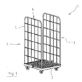
- the transport container according to Fig. 1 consists of a bottom element 2 with rollers arranged underneath.
- two side elements 3 are inserted opposite and extend substantially vertically upwards.
- Each side element 3 shows a lattice structure which is bounded and stabilized by a frame body 5 which circulates around the structure to the outside.
- the frame body 5 consists of a circular cross-section tube.
- an RFID transponder unit 4 is inserted in an upper horizontal portion of the frame body 5.
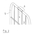
- Fig. 2 shows in more detail the embedding of the RFID transponder unit 4 in the frame body 5 of the side member 3.
- the cross-sectional profile of the frame body 5 has been deformed to accommodate the complementary formed to the deformation RFID transponder unit there.
- the frame body keeps its substantially circular cross-sectional shape.
- Fig. 3 shows a schematic sectional view of the embedding of the RFID transponder unit in the frame body 5 even more accurate. It can be seen, in particular, how, in the region of the mounting section 6, the frame body 5 has undergone a cross-sectional deformation 7 with respect to its originally circular cross-sectional shape Fig. 3 can be recognized as sickle-shaped or kidney-shaped. The resulting "bed" in the center of the original circular cross-section serves to accommodate the RFID transponder unit 4 formed complementary thereto. It can also be seen that the cross-sectional deformation 7 in conjunction with the RFID transponder unit 4 used is substantially the same again as the circular one Standard cross-section forms, the frame body 5 beyond the mounting portion 6 has. Since the RFID transponder unit 4 is inserted flush with the frame body 5 and does not protrude, it is well protected against mechanical loading or damage.
- Fig. 4a the RFID transponder unit 4 is shown in cross section. Good to see is in connection with Fig. 3 its shape complementary to the cross-sectional deformation 7.
- Fig. 4b shows the RFID transponder unit 4 in perspective view.
Landscapes
- Engineering & Computer Science (AREA)
- Chemical & Material Sciences (AREA)
- Combustion & Propulsion (AREA)
- Transportation (AREA)
- Mechanical Engineering (AREA)
- Details Of Rigid Or Semi-Rigid Containers (AREA)
- Radar Systems Or Details Thereof (AREA)
Applications Claiming Priority (1)
| Application Number | Priority Date | Filing Date | Title |
|---|---|---|---|
| DE200720005620 DE202007005620U1 (de) | 2007-04-17 | 2007-04-17 | Transportbehälter |
Publications (2)
| Publication Number | Publication Date |
|---|---|
| EP1982894A2 true EP1982894A2 (fr) | 2008-10-22 |
| EP1982894A3 EP1982894A3 (fr) | 2009-10-21 |
Family
ID=38329783
Family Applications (1)
| Application Number | Title | Priority Date | Filing Date |
|---|---|---|---|
| EP08005042A Withdrawn EP1982894A3 (fr) | 2007-04-17 | 2008-03-18 | Conteneur de transport |
Country Status (2)
| Country | Link |
|---|---|
| EP (1) | EP1982894A3 (fr) |
| DE (1) | DE202007005620U1 (fr) |
Cited By (3)
| Publication number | Priority date | Publication date | Assignee | Title |
|---|---|---|---|---|
| WO2009150304A1 (fr) * | 2008-06-13 | 2009-12-17 | Upm Raflatac Oy | Transpondeur |
| CN104443637A (zh) * | 2014-10-21 | 2015-03-25 | 常熟市意润达商业设备厂 | 新型仓储笼 |
| WO2017140527A1 (fr) * | 2016-02-15 | 2017-08-24 | Gea Food Solutions Bakel B.V. | Système de sécurité et de détection de chariot |
Families Citing this family (3)
| Publication number | Priority date | Publication date | Assignee | Title |
|---|---|---|---|---|
| DE102007061707A1 (de) | 2007-12-19 | 2009-06-25 | Technische Universität München | Flurförderzeug mit einer RFID-gestützten Einrichtung zur Identifikation von Ladungsgütern |
| NL2002790C2 (nl) * | 2009-04-24 | 2010-10-26 | Colpac Collapsible Containers B V | Houder voor het bevatten van producten, systeem en werkwijze met gebruikmaking van een dergelijke houder. |
| CN104443638A (zh) * | 2014-10-21 | 2015-03-25 | 常熟市意润达商业设备厂 | 仓储笼 |
Family Cites Families (5)
| Publication number | Priority date | Publication date | Assignee | Title |
|---|---|---|---|---|
| GB9620137D0 (en) * | 1996-09-27 | 1996-11-13 | Twil Handling & Display Ltd | Materials handling units |
| US20030156501A1 (en) * | 2002-01-14 | 2003-08-21 | Martin Spindel | Trackable storage unit system and method |
| US7660747B2 (en) * | 2005-06-28 | 2010-02-09 | Media Cart Holdings, Inc. | Media enabled shopping cart system with point of sale identification and method |
| JP4291809B2 (ja) * | 2005-09-29 | 2009-07-08 | 沖電気工業株式会社 | 搬送容器 |
| DE202007004241U1 (de) * | 2007-03-22 | 2007-05-24 | Rewe-Zentral Ag | RFID-Tag und Rollcontainer |
-
2007
- 2007-04-17 DE DE200720005620 patent/DE202007005620U1/de not_active Expired - Lifetime
-
2008
- 2008-03-18 EP EP08005042A patent/EP1982894A3/fr not_active Withdrawn
Cited By (6)
| Publication number | Priority date | Publication date | Assignee | Title |
|---|---|---|---|---|
| WO2009150304A1 (fr) * | 2008-06-13 | 2009-12-17 | Upm Raflatac Oy | Transpondeur |
| CN104443637A (zh) * | 2014-10-21 | 2015-03-25 | 常熟市意润达商业设备厂 | 新型仓储笼 |
| WO2017140527A1 (fr) * | 2016-02-15 | 2017-08-24 | Gea Food Solutions Bakel B.V. | Système de sécurité et de détection de chariot |
| CN108604305A (zh) * | 2016-02-15 | 2018-09-28 | Gea 食品策划巴克尔公司 | 推车检测和安全系统 |
| CN108604305B (zh) * | 2016-02-15 | 2021-10-12 | Gea 食品策划巴克尔公司 | 推车检测和安全系统 |
| US11536300B2 (en) | 2016-02-15 | 2022-12-27 | Gea Food Solutions Bakel B.V. | Trolley detection and safety system |
Also Published As
| Publication number | Publication date |
|---|---|
| EP1982894A3 (fr) | 2009-10-21 |
| DE202007005620U1 (de) | 2007-08-02 |
Similar Documents
| Publication | Publication Date | Title |
|---|---|---|
| EP1982894A2 (fr) | Conteneur de transport | |
| EP2913277B1 (fr) | Élément de sol pour un conteneur de fret et/ou une palette de fret et procédé de fabrication d'un élément de sol correspondant | |
| EP2986522B1 (fr) | Récipient de transport pourvu d'un support d'identification | |
| EP2649677B1 (fr) | Transpondeur rfid | |
| DE202008001549U1 (de) | RFID-Transponder | |
| EP2508461B1 (fr) | Elément de réception de charge doté d'un support de données lisible sans contact | |
| EP3439985B1 (fr) | Conteneur palette | |
| DE4115708A1 (de) | Foerdereinrichtung | |
| DE19841992C1 (de) | Anschlußvorrichtung | |
| DE4404392C2 (de) | Drehverriegelung zum lösbaren Verbinden von Eckbeschlägen aufeinanderstehender Container | |
| WO2010149181A1 (fr) | Élément de verrouillage | |
| DE102020125209B4 (de) | Regalpaneel mit Verformung | |
| DE4434286C1 (de) | Verwendung eines plattenförmigen Trägers zur Halterung von einem Stapel Flachdichtungen | |
| DE102011055287A1 (de) | Verbindungsmittel | |
| DE2952485A1 (de) | Vorrichtung zur befestigung von paletten in einem rechteckigen behaelter | |
| DE69005888T2 (de) | Vorrichtung zur Befestigung von Gegenständen auf einer beliebigen Unterlage und Gegenstand, insbesondere Gehäuse, versehen mit mindestens einer derartigen Befestigungsvorrichtung. | |
| AT513375B1 (de) | Eckbeschlag | |
| EP0994041B1 (fr) | Dispositif de transport en matière plastique avec moyens d'identification | |
| DE102024002307B3 (de) | Transportwagensystem mit Stapelsicherung | |
| DE202019103102U1 (de) | Abweisblech für einen Thermobehälter und Thermobehälter | |
| DE9408233U1 (de) | Behälter oder Einsatz für Behälter | |
| DE202019102679U1 (de) | Behälter mit einem Einlegeboden | |
| DE102025103003A1 (de) | Lagerstation zum Lagern eines Ladungsträgers | |
| DE8801454U1 (de) | Vielzweck-Transportgerät | |
| DE29913025U1 (de) | Verstärkbarer Verpackungskarton |
Legal Events
| Date | Code | Title | Description |
|---|---|---|---|
| PUAI | Public reference made under article 153(3) epc to a published international application that has entered the european phase |
Free format text: ORIGINAL CODE: 0009012 |
|
| AK | Designated contracting states |
Kind code of ref document: A2 Designated state(s): AT BE BG CH CY CZ DE DK EE ES FI FR GB GR HR HU IE IS IT LI LT LU LV MC MT NL NO PL PT RO SE SI SK TR |
|
| AX | Request for extension of the european patent |
Extension state: AL BA MK RS |
|
| PUAL | Search report despatched |
Free format text: ORIGINAL CODE: 0009013 |
|
| AK | Designated contracting states |
Kind code of ref document: A3 Designated state(s): AT BE BG CH CY CZ DE DK EE ES FI FR GB GR HR HU IE IS IT LI LT LU LV MC MT NL NO PL PT RO SE SI SK TR |
|
| AX | Request for extension of the european patent |
Extension state: AL BA MK RS |
|
| AKX | Designation fees paid | ||
| STAA | Information on the status of an ep patent application or granted ep patent |
Free format text: STATUS: THE APPLICATION IS DEEMED TO BE WITHDRAWN |
|
| 18D | Application deemed to be withdrawn |
Effective date: 20100422 |
|
| REG | Reference to a national code |
Ref country code: DE Ref legal event code: 8566 |