EP2508461B1 - Elément de réception de charge doté d'un support de données lisible sans contact - Google Patents
Elément de réception de charge doté d'un support de données lisible sans contact Download PDFInfo
- Publication number
- EP2508461B1 EP2508461B1 EP12151764.3A EP12151764A EP2508461B1 EP 2508461 B1 EP2508461 B1 EP 2508461B1 EP 12151764 A EP12151764 A EP 12151764A EP 2508461 B1 EP2508461 B1 EP 2508461B1
- Authority
- EP
- European Patent Office
- Prior art keywords
- data carrier
- load handling
- handling part
- load
- clamping element
- Prior art date
- Legal status (The legal status is an assumption and is not a legal conclusion. Google has not performed a legal analysis and makes no representation as to the accuracy of the status listed.)
- Active
Links
Images









Classifications
-
- B—PERFORMING OPERATIONS; TRANSPORTING
- B66—HOISTING; LIFTING; HAULING
- B66C—CRANES; LOAD-ENGAGING ELEMENTS OR DEVICES FOR CRANES, CAPSTANS, WINCHES, OR TACKLES
- B66C1/00—Load-engaging elements or devices attached to lifting or lowering gear of cranes or adapted for connection therewith for transmitting lifting forces to articles or groups of articles
- B66C1/10—Load-engaging elements or devices attached to lifting or lowering gear of cranes or adapted for connection therewith for transmitting lifting forces to articles or groups of articles by mechanical means
- B66C1/22—Rigid members, e.g. L-shaped members, with parts engaging the under surface of the loads; Crane hooks
- B66C1/34—Crane hooks
-
- B—PERFORMING OPERATIONS; TRANSPORTING
- B66—HOISTING; LIFTING; HAULING
- B66C—CRANES; LOAD-ENGAGING ELEMENTS OR DEVICES FOR CRANES, CAPSTANS, WINCHES, OR TACKLES
- B66C1/00—Load-engaging elements or devices attached to lifting or lowering gear of cranes or adapted for connection therewith for transmitting lifting forces to articles or groups of articles
- B66C1/10—Load-engaging elements or devices attached to lifting or lowering gear of cranes or adapted for connection therewith for transmitting lifting forces to articles or groups of articles by mechanical means
- B66C1/12—Slings comprising chains, wires, ropes, or bands; Nets
-
- B—PERFORMING OPERATIONS; TRANSPORTING
- B66—HOISTING; LIFTING; HAULING
- B66C—CRANES; LOAD-ENGAGING ELEMENTS OR DEVICES FOR CRANES, CAPSTANS, WINCHES, OR TACKLES
- B66C1/00—Load-engaging elements or devices attached to lifting or lowering gear of cranes or adapted for connection therewith for transmitting lifting forces to articles or groups of articles
- B66C1/10—Load-engaging elements or devices attached to lifting or lowering gear of cranes or adapted for connection therewith for transmitting lifting forces to articles or groups of articles by mechanical means
- B66C1/62—Load-engaging elements or devices attached to lifting or lowering gear of cranes or adapted for connection therewith for transmitting lifting forces to articles or groups of articles by mechanical means comprising article-engaging members of a shape complementary to that of the articles to be handled
- B66C1/66—Load-engaging elements or devices attached to lifting or lowering gear of cranes or adapted for connection therewith for transmitting lifting forces to articles or groups of articles by mechanical means comprising article-engaging members of a shape complementary to that of the articles to be handled for engaging holes, recesses, or abutments on articles specially provided for facilitating handling thereof
-
- B—PERFORMING OPERATIONS; TRANSPORTING
- B66—HOISTING; LIFTING; HAULING
- B66C—CRANES; LOAD-ENGAGING ELEMENTS OR DEVICES FOR CRANES, CAPSTANS, WINCHES, OR TACKLES
- B66C13/00—Other constructional features or details
- B66C13/16—Applications of indicating, registering, or weighing devices
Definitions
- the invention relates to a load-receiving part for the stop, lifting, lashing and / or conveyor technology, in which at least one non-contact readable data carrier is integrated.
- chain links, attachment points, hooks, eyes, shackles, claws and clamping elements are used as load-bearing parts in the lifting, lifting, lashing and / or conveying technology and are usually made of an electrically conductive material such as steel.
- a load receiving part with the features mentioned is for example from the DE 10036014 A1 known.
- the load-receiving parts for receiving non-contact readable data carriers are specially designed.
- chain links additionally have a web and load hooks additionally have an eye in order to be able to arrange data carriers outside a region defined by the respective operational stresses.
- the DE10234626 B4 deals with the integration of a pulse generator and a sensor spaced apart in a load receiving part.
- WO 2004/085985 is a life sensor known, which can also be used in load handling equipment, such as a round steel chain.
- the publication EP 1 864 939 A1 describes a system and method for the identification of lifting devices by means of RFID transponders.
- the transponders are attached to the outside of the devices.
- the publication WO 2011/002713 A2 describes a shackle, which can also be equipped with a transponder.
- a data carrier is shown, which is housed in a capsule, which can be integrated into a workpiece.
- the publication DE 198 07 284 A1 describes a transponder which is provided with a pin which can be inserted into a tree or a wooden beam, wherein the transponder is then on the surface of the tree or workpiece.
- the invention has the goal of further improving the known from the prior art load-bearing parts with integrated disk in terms of manufacturing effort and use.
- the wrapping of the disk is opposite to that from the DE10036014 A1 known potting less expensive.
- a data carrier in particular an RFID element that is a transponder in question.
- the invention can be further improved by the following, each advantageous and combinable with each other, embodiments.
- the retaining ribs are preferably crushed in the turned-on state and hold the data carrier non-positively in the load receiving part. In addition, centered by the ribs of the disk automatically in the intended for him recording the load-receiving part.
- the holding ribs preferably extend along a wrapping direction in order to simplify the assembly. A precise centering is favored by a preferably uniform distribution of the holding ribs in the circumferential direction.
- At least one end of the disk may be provided with a radially projecting over the retaining ribs, preferably circumferential collar.
- the collar is preferably located at the end of the data carrier opposite to the direction of impact.
- the holding ribs and a gap between the data carriers and the load receiving part may be covered, so that no tool between the gap or the holding ribs for releasing the data carrier can be introduced.
- the collar can also serve as a seal which prevents the entry of contaminants and moisture into the gap between the data carrier and the load receiving part.
- the collar may in particular be provided with a sealing surface which is inclined by 45 ° relative to the peripheral surface or the direction of impact and which faces away from the outer surface of the load-receiving part or in the direction of impact.
- the recording in the load receiving part, in which the disk is taken may be provided with a complementarily configured, preferably also inclined sealing surface, so that the two sealing surfaces are sealingly brought into abutment by the hitting.
- the inclination of the sealing surfaces relative to the direction of impact thereby increases the contact pressure between the sealing surfaces by a slight radial compression of the collar.
- the data carrier can be arranged in a fastening element of the load-receiving part.
- fasteners are for example screws, nuts, bolts or pins. They serve to attach the load-carrying part to a support or to produce the integral cohesion of the load-bearing part.
- the data carrier can be wrapped in an end face of such a fastener or in a peripheral surface which serves as a key surface for example, a wrench.
- an existing load receiving part must not be structurally changed. An intervention in its supporting structure and possible impairments can be avoided, it must be created alone a recording for the disk in the fastener.
- the data carrier can also be taken in an already existing receptacle for a fastening element of the load-receiving part.
- an intervention in the structure of the load-receiving part is not necessary; it only becomes already existing structures used to attach the disk. Examples of such recordings are through holes or insertion openings for pins or screws.
- the outer surface of the load-receiving part facing the end of the data carrier is preferably aligned with the surface of the load-receiving part. This allows a simple reading of the data carrier in spite of the disk surrounding, electrically conductive material from which the load receiving part can be made.
- the reading-side end of the data carrier is preferably located in a flat region of the load-receiving part, so that the data carrier is easily accessible from all sides for a reading device.
- the data carrier can also be recessed in its receptacle in order to make it difficult to read out the data carrier and thus access the data stored there.
- a specially designed reading device can be used which has a read head which can be inserted into the receptacle as far as the read-out-side surface of the data carrier.
- the load receiving part may be provided according to a further advantageous embodiment with an identification tag, which has on at least one surface of a user readable information about the load receiving part.
- the disk can be introduced. This has the advantage that the data carrier is particularly easy to access and sits in the place where information about the load receiving part is already presented to a user.
- the data carrier is preferably designed in the shape of a pilla or button and may have a substantially cylindrical basic body.
- the height of the data carrier in the direction of impact is preferably smaller than the diameter of the data carrier, so that the data carrier is flat.
- only a flat receptacle is necessary for receiving the data carrier, which only slightly affects the load-bearing cross section of the load receiving part.
- a simple accessibility of the data carrier is ensured according to a further advantageous embodiment, when the data carrier is hammered at a position of the load receiving part, which is introduced between a holding portion on which the load to be carried in the load receiving part, and a mounting portion on which the load receiving part is attached to a lifting means such as a chain or rope is arranged.
- the data carrier is arranged in a region which can not be swept by the holding means arranged on the holding portion and the means arranged on the attachment portion, so that they can not hinder access to the data carrier.
- relief-like orientation aids can be arranged on the load receiving part, preferably adjacent to the data carrier or at an opening of the receptacle for the data carrier.
- the orientation aids may in particular be formed by an embossing process, such as forging, so that they can withstand harsh operation and remain legible.
- the load-receiving part is provided with an opening for suspending at least one further load-bearing member.
- load-bearing parts are, for example chain links or eyelets of stop or lashing.
- a clamping element receiving the data carrier can in particular be introduced in a form-fitting manner.
- This embodiment makes it possible to integrate the disk without interference with the supporting structure of the load-receiving part.
- the load receiving part can also be retrofitted.
- the load-receiving part provided with the clamping element can be recognized quickly, which is advantageous in particular for chain strands having considerable length.
- the clamping element is preferably made of a durable plastic. To avoid damage, the clamping element can be flush with a side surface of the load receiving part. In this embodiment, no portions of the clamping element protrude from the outer contour of the load-receiving part.
- this can be composed of at least two parts, of which at least one penetrates the opening.
- the two parts of the clamping element can in particular be positively connected to each other. They can be arranged on both sides of a plane defined by the opening.
- the clamping element can be positively connected to an opening facing the inside of the load receiving part.
- the already existing cross-sectional shape can be used for clamping the clamping element in this embodiment.
- the clamping element can also be arranged completely inside the opening.
- the clamping element is provided according to a further advantageous embodiment with at least one recess in which the at least one further, suspended in the opening load receiving part is added, so can the arrangement formed from the two load-receiving parts set in their position of use.
- the suspended in the load receiving part further load-receiving part is already prepositioned and can not be removed from the position of use. This increases the reliability.
- the invention relates to a retrofit kit for load-receiving parts of the stop, lifting, lashing and / or conveyor technology, which are provided with at least one opening for suspending other load-receiving parts.
- a simple retrofit to simplify maintenance and component testing can be achieved by a clamping element, which is provided with a non-contact readable data carrier and designed with the opening form-fitting engageable.
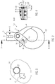
- Fig. 1 shows a load-receiving part 1 in the form of a load hook 2, in which a hook mouth 3 can be closed by a movable safety lock 4.
- the hook 1 has a fastening-side end 5 with which the hook is suspended in a lifting means (not shown), for example a chain or a wire rope.
- the attachment-side end 5 can, as Fig. 1 shows, be configured in the form of a fork 6 and a receptacle 7 for the lifting means, here a chain, have.
- a receptacle 7 is a by a pin 8, for example, an impact sleeve, secured retaining pin 9 is arranged.
- the retaining pin 9 passes through the receptacle 7 by extending from a fork leg 10 of the fork 6 to the other fork leg 11.
- At the load-side end 12 of the load hook is provided with a holding portion 13, in which a load-bearing stop means, so alternatively lashing or funding can be hung.
- the load-receiving means 1 is provided with an electronically contactless readable data carrier 14, for example an RFID chip or a data carrier 14.
- the data carrier 14 is hammered into the load receiving part 1.
- the load receiving part 1 is stored characterizing data. These data include, for example, manufacturer-related data on design, mechanical properties and / or information on its production.
- a part of the data stored on the data carrier 14 can also be modified and stored again.
- data in the data carrier 14 can be stored via maintenance measures taken.
- the data carrier 14 is preferably self-sufficient and does not have its own energy source.
- the energy is provided by an electromagnetic alternating field of a reading device. About the alternating field, the information between the disk and the reader are transported.
- metallic stop means this is preferably spaced in a region 15 arranged from the two ends 5, 12 and outside the range of movement of the lifting and slinging means suspended therein.
- the area 15 has a sufficient distance to the lifting means and the stop means, so that its accessibility is not hindered by these means.
- the disk 14 can, as Fig. 1 shows, be arranged in a flat region 16 of the load-receiving part 1. Adjacent to the disk 14 is a relief-like marking 17, which serves as a guide to find the disk 14 during operation faster.
- the region 15 in which the disk 14 is arranged in the range of a power flow 18, along which the forces from the load to the fastening side end 5, 12 are passed through the load receiving part 1.
- the flat region 15 may be formed by a wart-shaped elevation whose height corresponds at least to a height of the data carrier 14.
- Fig. 2 shows a further embodiment of a load-receiving part 1 according to the invention, here as a further variant of a load hook 2.
- a data carrier 14 is hammered in the central region between the fastening-side end 5 and the load-side end 12, the position of which is emphasized by a preferably relief-like, adjacent marking 17 easily recognizable.
- a receptacle 7 for a fastening element 20, here an impact bolt or an impact sleeve is closed by the data carrier 14.
- the receptacle 7 simultaneously serves as a receptacle 19 for the data carrier 14.
- the fastener 20 secures a closure 4 for the hook mouth 3 in the closed position.
- a reading-side surface 21 of the data carrier is preferably aligned with an adjacent surface 22 of the load-receiving part 1.
- On the read-side surface 21 of the data carrier 14 are not shown transmitting and receiving devices. she should be as accessible as possible and not covered by electrically conductive materials.
- the data carrier 14 is hammered into the receptacle 19 in a direction of impact E.
- the data carrier 14 is preferably pills or button-shaped. It has a cylindrical basic shape, the diameter D is greater than the height H. Radially from a peripheral surface 23 'of the disk 14 projecting retaining ribs 23, which are deformed upon impact and establish a frictional connection with the inner wall of the receptacle 19, secure the disk 14th in the receptacle 19.
- the holding ribs same manufacturing tolerances and center the disk in the receptacle 19, so that the opening 19 does not have to be processed too precisely.
- the holding ribs preferably do not extend over the entire, but at least over half the height H of the data carrier 14. In the direction of impact E, the holding ribs end in a chamfered ramp.
- FIGS. 5 and 6 A modification of the embodiment of Fig. 2 is in the FIGS. 5 and 6 shown.
- Fig. 5 is a section in the direction V of Fig. 2 shown.
- the data carrier 14 is arranged in an end face 24 of the retaining bolt 9, which also serves as a fastening means 20.
- the data carrier 14 is arranged in that end face 24 of the retaining bolt 9, which is accessible from the outside in the receptacle 19.
- the surface 21 of the data carrier 14 is well protected in the receptacle 19 against external influences.
- the reading of the data carrier 14 is difficult in the interior of the receptacle 19, unless a plugged into the receptacle 19, adapted to the specific configuration of the load receiving means 1 reader (not shown) is used to reduce the disturbing influences of the metallic environment.
- Fig. 6 is exemplified that an insertion direction F, in which the fastening means 20 is inserted into the load receiving part 1, opposite to the direction of impact E of the data carrier 14 may be directed.
- the receptacle 19 of the retaining pin 9 is held between a stop 26 and the securing element 8 on the opposite end of the disk 14 27.
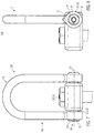
- a lifting point 28 with a preferably pivotable about an axis 29, bow-shaped holding portion 13 shown as a load receiving part.
- the attachment point is fixedly attached via a fastening element 20, here a screw 30, to a load (not shown) to be lifted, such as a container.
- the holding section 13 serves for example for receiving a load hook 2, as in the Fig. 1 and 2 is shown.
- the data carrier 14 is hammered in this embodiment in an end face 24 of a head 31 of a serving as a fastening means 20 for the holding portion 13 axle pin 32. At this point, the disk 14 is easily accessible in the mounted state.
- Fig. 8 shows that the disk 14 is preferably centrally in the cross section of the axle 32 and its head 31.
- Fig. 9 shows a variant of the in the FIGS. 7 and 8 illustrated embodiment.
- the data carrier 14 is arranged in a preferably flat region 16 on a lateral outer surface 33 of the bow-shaped holding portion 13.
- Front and back sides 34, 34 ' can be provided with relief-like, for example, projecting markings 17, which point to the data carrier 14, so that it can be easily found.
- Fig. 10 shows the view along the arrow X of Fig. 9 , It can be seen that the data carrier 14 is arranged in the region of the force flow 18. However, due to the flat, button-like configuration, the data carrier 14 projects only into the surface region of the load-receiving part 1 (FIG. Fig. 20, 21 . 23 ), so that the load-bearing cross-section of the load-receiving part 1, the receptacle for the disk 14 is only slightly weakened.
- Fig. 11 is a further embodiment of a load-receiving part 1, shown here in the form of a chain or suspension link 35.
- the load receiving part 1 of Fig. 11 is provided on a straight leg 36 with a flattening 37, in the captive, for example, a shackle 38 can be hung.
- the load receiving part 1 can also be provided with a trailer 39.
- the area 37 there is again a flat area 16, which facilitates the read-out of the data carrier 14.
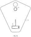
- Fig. 13 shows a trailer 39, which may be part of a load-bearing part 1, such as Fig. 11 shows.
- the trailer 39 is provided with a data carrier 14 and with markings 40, which allow identification of the load-bearing part 1 used with the trailer 39.
- the data carrier 14 can also be hammered into other fastening means 20 which are used in the load receiving part 1. So can after Fig. 14 the disk 14 in screws or bolts 41 at the end face 24, here in the screw head 42, be introduced. The end face 24 may be provided with markings 17. The disk 14 may also be taken in the end of the screw. This is particularly useful when it is countered with a mother and the end of the screw thus protrudes slightly and is accessible to a reader.
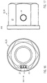
- the data carrier 14 can also be hammered into a peripheral surface 43, such as FIGS. 16 and 17 demonstrate.
- the reading-side surface 21 of the data carrier 14 should not protrude from the peripheral surface 43, so that the disk is not damaged when attaching wrenches.
- Fig. 18 shows a load-receiving part 1 in the form of a fixed eye-shaped attachment point 28 in which a chain or suspension link 35 is received.
- the load receiving part 1 is provided with a fastening means 20 which has a polygonal, here hexagonal, cross-section at at least one point, so that a key can be attached at this point.
- the outer key surface 33 may, as in the fastener 20 of the FIGS. 16 and 17 be provided with a data carrier 14.
- Fig. 19 shows an enlarged section of a surface 22 of the load-receiving part 1.
- a cap 45 is attached, which serves as a screen to hide the underlying data carrier 14.
- the cap 45 may additionally serve as a seal which shields the interior of the receptacle 19 against external influences.
- the cap 45 is preferably made of a dielectric material.
- the risk of misreading and manipulating the data stored on the data carrier 14 is reduced due to the hidden installation of the data carrier 14.
- the data carrier 14 is formed in the previously described button or disc shape and provided with holding ribs 23.
- Fig. 20 In the case of the data carrier 14, an opening 46 forming the receptacle 19 is provided with an outlet 47 below the data carrier.
- the cap 45 has a curved surface. In the embodiment of the Fig. 21 the cap 45 is arranged straight and in alignment with the surface 22 of the load-receiving part 1.
- FIGS. 22 and 23 an embodiment is shown in which the read-out side of the data carrier 14 is provided with a collar 48.
- the collar 48 protrudes beyond the retaining ribs 23 in the radial direction and has a sealing surface 49 pointing in the direction of impact E, which extends in particular at a 45 ° angle relative to the direction of impact E, which corresponds to the direction of the vertical axis of the cylindrical base body of the data carrier 14 can.
- the sealing surface 49 also serves as a stop in order to limit the depth of impact of the data carrier and to position the data carrier.
- the receptacle 19 terminates counter to the direction of impact E in a chamfered sealing surface 50 against which the sealing surface 49 of the data carrier 14 is pressed in the turned-on state.
- the sealing collar 48 By the sealing collar 48, the receptacle 19 is sealed for the disk 14.
- the disk 14 acts as a sealing plug.
- FIGS. 24 to 30 show a load-receiving part 1 in the form of a chain link 51.
- the load receiving part 1 may also be an eyelet (not shown).
- the load receiving part 1 according to Fig. 24 is provided with a clamping element 52 which holds the disk 14.
- the clamping element 52 is inserted into an opening 53 of the load-receiving part 1.
- Chain links 54 inserted into the opening 53 are received in recesses 55 of the clamping element 52 in such a way that they maintain their original mobility, as indicated by the arrows 56, relative to the chain link 51 and at the same time in the in FIG Fig. 24 shown position of use are prepositioned.
- the clamping element 52 is arranged between the two chain links 54 and keeps them at a distance from each other.
- the clamping element 52 may overlap in the direction perpendicular to the plane of the opening 53, the straight legs 57 of the chain link 51 and so make the positive connection.
- the clamping element 52 extends in the longitudinal direction of the opening 53 substantially over the straight portion of the legs 57, so that the opening 53 remains free in the curved region of the bow 58.
- the clamping element 52 is in positive engagement with the inner side 59 facing the opening 53, in particular the inner sides of the legs 57, of the chain link 51 or load-receiving part 1.
- the clamping element 52 is held captive in the load receiving part 1, so that it can not be solved and removed by the forces occurring in normal operation.
- the data carrier 14 is preferably arranged centrally between the adjacent chain links 54.
- the clamping element 52 may be made in one piece from a body, preferably made of plastic.
- an end face 24 of the clamping member 52 of the disk 14 is taken.
- the end face 24 closes flush with the chain link 51 z. B. whose legs 57 from, so that no protrusions occur and the outer surface 60 of the load-receiving part 1 or chain link 51 preferably continues smoothly in the outer surface of the clamping member 52.
- the clamping element 52 is completely received in the opening 53.
- the clamping element 52 On its sides facing the legs 57, the clamping element 52 recesses 61, in which the inner sides 59 of the legs 57 are positively received, so that the positive connection, the movement of the clamping element in the direction perpendicular to the opening 53 (FIGS. Fig. 24 ) locks. In the longitudinal direction of the chain link 51, the mobility of the clamping element 52 is limited by the curvature of the bow 58 and the chain links 54 received in the receptacles 55.
- the clamping element 52 is pressed or knocked into the opening 53.
- the clamping element 52 has at least two parts 63, 64 which are connected to one another in a form-fitting manner and which are in turn held together in a form-fitting manner in the opening 53.
- a part 63 protrudes through the opening 53 (FIG. Fig. 24 ) or spanned by the opening 53 plane 65, which is preferably determined by the narrowest clear width of the opening 53.
- the parts 63, 64 are preferably arranged on opposite sides with respect to the plane 65.
- the two parts 63, 64 are inserted from their respective side on the load receiving part 1 and thereby joined together.
- the structure and function of the embodiment correspond to the Fig. 26 those of the embodiment of Fig. 25 ,
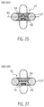
- the clamping element 52 also has at least two parts 63, 64.
- the parts 63, 64 are materially connected in each case to the load-receiving part 1 or chain link 51.
- the part 63 As in the embodiment of Fig. 26 is only a part, here the part 63, provided with the disk 14. Otherwise, structure and function of the embodiment correspond to the Fig. 27 those of the embodiment of Fig. 26 ,
- a further embodiment of a clamping element 52 is shown with a disk 14.
- the disk 14 is more easily accessible in this embodiment, because it is equal to the outer surfaces 60 of the adjacent chain links 54.
- the measured in the direction transverse to the opening 53 height of the clamping element 52 is only slightly smaller, preferably not greater than the outer width of the chain link 51st
- the clamping element 52 of Fig. 28, 29 is preferably made of metal and also has at least two parts 63, 64 which are positively connected, for example by riveting, screwing or pressing together captive.
- the one, the opening 53 of the chain link 51 passing through part 63 may preferably in each plane parallel to the plane 65 of the opening 53 (see. Fig. 26 ) have a circular cross section in order to restrict the mobility of the chain links relative to each other as little as possible.
- the clamping element 52 has guide surfaces 66, which face the bow 58 of the chain links and are formed complementary to their outer curvature.
- the chain links 54 maintain their mobility with respect to the chain link 51 and are pre-positioned in the position of use.
- the trailer 39 is preferably made of a forged, tempered bending member made of flat material.
- the bending member can be subsequently introduced captive in a press or a vise in the chain assembly. On a flat side of the disk 14 is taken.
- Fig. 32 shows a modification of the load-receiving part 1 in the form of a Ein vonglieds 35.
- a disk 14 is taken in the leg 36 of the Ein vonglieds a disk 14 is taken.
- a reading or surface of the data carrier 21 is parallel to the plane spanned by the opening of the Ein vonglieds 35 level.
Landscapes
- Engineering & Computer Science (AREA)
- Mechanical Engineering (AREA)
- Connection Of Plates (AREA)
- Package Frames And Binding Bands (AREA)
- Fittings On The Vehicle Exterior For Carrying Loads, And Devices For Holding Or Mounting Articles (AREA)
- Automatic Assembly (AREA)
- Packaging Of Machine Parts And Wound Products (AREA)
Claims (18)
- Pièce de reprise ou de support de charge (1) destinée au domaine technique de l'élingage, du levage, de l'amarrage et/ou du transport, dans lequel est intégré au moins un support de données (14) pouvant être lu sans contact, caractérisée en ce que le support de données (4) est pourvu, sur sa surface périphérique (23'), de nervures de maintien (23) en saillie radiale, et est enchâssé dans la pièce de reprise de charge (1).
- Pièce de reprise de charge (1) selon la revendication 1, caractérisée en ce que le support de données (14) est pourvu, à au moins une extrémité, d'une collerette (48) en saillie dans la direction radiale.
- Pièce de reprise de charge (1) selon la revendication 2, caractérisée en ce que la collerette (48) couvre au moins les nervures de maintien (23).
- Pièce de reprise de charge (1) selon la revendication 2 ou la revendication 3, caractérisée en ce que la collerette (48) assure l'étanchéité vers l'extérieur d'un logement d'accueil (19) dans lequel est agencé le support de données (14).
- Pièce de reprise de charge (1) selon l'une des revendications 1 à 4, caractérisée en ce que le support de données (14) est inséré dans un élément de fixation (9, 30, 32) de la pièce de reprise de charge.
- Pièce de reprise de charge (1) selon la revendication 5, caractérisée en ce que le support de données (14) est agencé dans une vis ou un écrou.
- Pièce de reprise de charge (1) selon la revendication 6, caractérisée en ce que le support de données (14) est agencé sur une face frontale (24) de l'élément de fixation (8, 9, 30, 32).
- Pièce de reprise de charge (1) selon l'une des revendications 1 à 7, caractérisée en ce qu'une extrémité pouvant être lue du support de données (14), affleure au niveau d'une surface (22) de la pièce de reprise de charge (1).
- Pièce de reprise de charge (1) selon l'une des revendications 1 à 8, caractérisée en ce que la pièce de reprise de charge (1) est munie d'une étiquette (39) dans laquelle est intégrée le support de données (14).
- Pièce de reprise de charge (1) selon l'une des revendications 1 à 9, caractérisée en ce qu'au voisinage du support de données (14) sont agencées des aides à l'orientation (17) en relief.
- Pièce de reprise de charge (1) selon l'une des revendications 1 à 10, caractérisée en ce que le support de données (14) est agencé dans un logement d'accueil pour un élément de fixation (8, 9, 30, 32) de la pièce de reprise de charge (1).
- Pièce de reprise de charge (1) selon l'une des revendications 1 à 11, caractérisée en ce que le support de données (14) est recouvert par un cabochon (45).
- Pièce de reprise de charge (1), notamment un maillon de chaîne (51) ou un anneau, selon l'une des revendications 1 à 12, avec une ouverture (53) pour l'accrochage d'au moins une autre pièce de reprise de charge (1, 54), notamment un maillon de chaîne (54), caractérisée en ce que dans l'ouverture (53) est fixé un élément de coincement (52) accueillant le support de données (14).
- Pièce de reprise de charge (1) selon la revendication 13, caractérisée en ce que l'élément de coincement (52) se termine de manière à affleurer au niveau de la pièce de reprise de charge (1).
- Pièce de reprise de charge (1) selon la revendication 13 ou la revendication 14, caractérisée en ce que l'élément de coincement (52) est constitué d'au moins deux parties (63, 64) dont l'une au moins traverse ladite ouverture (53).
- Pièce de reprise de charge (1) selon l'une des revendications 13 à 15, caractérisée en ce que l'élément de coincement (52) est lié par complémentarité de formes avec un côté intérieur (59) de la pièce de reprise de charge (1), qui est dirigé vers ladite ouverture (53).
- Pièce de reprise de charge (1) selon l'une des revendications 13 à 15, caractérisée en ce que l'élément de coincement (52) présente au moins un évidement (55) dans lequel est reçue de manière mobile, ladite au moins une autre pièce de reprise de charge (1, 54) accrochée dans ladite ouverture (53).
- Kit d'équipement ultérieur pour pièces de reprise de charge (1) destinées au domaine technique de l'élingage, du levage, de l'amarrage et/ou du transport, qui sont pourvues d'au moins une ouverture (53) pour l'accrochage d'autres pièces de reprise de charge (1), caractérisé par un élément de coincement (52), qui est doté d'un support de données (14) pouvant être lu sans contact, et peut être amené en prise par complémentarité de formes avec l'ouverture (53), le support de données (14) étant pourvu, sur sa surface périphérique (23'), de nervures de maintien (23) en saillie radiale, et étant enchâssé dans l'élément de coincement (52).
Applications Claiming Priority (1)
| Application Number | Priority Date | Filing Date | Title |
|---|---|---|---|
| DE102011001787A DE102011001787A1 (de) | 2011-04-04 | 2011-04-04 | Lastaufnahmeteil mit berührungslos auslesbarem Datenträger |
Publications (2)
| Publication Number | Publication Date |
|---|---|
| EP2508461A1 EP2508461A1 (fr) | 2012-10-10 |
| EP2508461B1 true EP2508461B1 (fr) | 2016-03-30 |
Family
ID=45558550
Family Applications (1)
| Application Number | Title | Priority Date | Filing Date |
|---|---|---|---|
| EP12151764.3A Active EP2508461B1 (fr) | 2011-04-04 | 2012-01-19 | Elément de réception de charge doté d'un support de données lisible sans contact |
Country Status (4)
| Country | Link |
|---|---|
| EP (1) | EP2508461B1 (fr) |
| CN (1) | CN102734387B (fr) |
| AU (1) | AU2012201799B2 (fr) |
| DE (1) | DE102011001787A1 (fr) |
Cited By (3)
| Publication number | Priority date | Publication date | Assignee | Title |
|---|---|---|---|---|
| US10242306B1 (en) | 2017-09-08 | 2019-03-26 | Yoke Industrial Corp. | Contactless data carrier |
| US10242304B1 (en) | 2017-09-20 | 2019-03-26 | Yoke Industrial Corp. | Contactless data carrier |
| DE102019008576A1 (de) * | 2019-12-11 | 2021-06-17 | Ruag Ammotec Gmbh | Einrichtung zum lokalen Zuordnen von elektronischen Daten zu einem Festkörper und System zum Kennzeichnen und Identifizieren von Festkörpern |
Families Citing this family (6)
| Publication number | Priority date | Publication date | Assignee | Title |
|---|---|---|---|---|
| US9511245B2 (en) | 2014-03-28 | 2016-12-06 | International Business Machines Corporation | Safety harness monitoring and alerting system |
| ES2550734B1 (es) * | 2014-05-08 | 2016-09-14 | Vicinay Sestao, S.L. | Contrete para eslabones de cadena |
| TWI638765B (zh) | 2017-09-08 | 2018-10-21 | 振鋒企業股份有限公司 | Non-contact data carrier |
| CN109492738B (zh) * | 2017-09-13 | 2022-05-03 | 振锋企业股份有限公司 | 非接触式数据载体 |
| CN109492739B (zh) * | 2017-09-13 | 2022-04-01 | 振锋企业股份有限公司 | 非接触式数据载体 |
| CN109583550A (zh) * | 2017-09-28 | 2019-04-05 | 振锋企业股份有限公司 | 非接触式数据载体 |
Family Cites Families (10)
| Publication number | Priority date | Publication date | Assignee | Title |
|---|---|---|---|---|
| DE19807284C2 (de) * | 1998-02-23 | 2000-10-05 | Reinhard Jurisch | Einrichtung und Verfahren zur Registrierung und Verwaltung von Bäumen, sowie mit einem Transponder versehener Baum oder Holzbalken |
| DE10036014C2 (de) | 2000-07-25 | 2003-10-23 | Thiele Gmbh & Co Kg | Sicherheitsbauteil aus Stahl für die Hebe-, Zurr-, Förder- oder Gewinnungstechnik |
| DE10234626B4 (de) | 2002-07-29 | 2006-02-23 | Thiele Gmbh & Co. Kg | Sicherheitsbauteile aus Stahl für die Hebe-,Zurr-,Förder -und Gewinnungstechnik |
| WO2004085985A1 (fr) | 2003-03-27 | 2004-10-07 | Thiele Gmbh & Co. Kg | Capteur de duree de vie |
| DE202005019359U1 (de) * | 2005-12-10 | 2006-02-16 | J. D. Theile Gmbh & Co. Kg | Anschlagpunkt |
| US7825770B2 (en) * | 2006-06-08 | 2010-11-02 | The Crosby Group LLC | System and method of identification, inspection and training for material lifting products |
| JP4708309B2 (ja) * | 2006-10-30 | 2011-06-22 | Ykk株式会社 | 連結具 |
| DE102007035144A1 (de) * | 2007-07-25 | 2009-01-29 | Ralf Bux | Vorrichtung und Verfahren zur Individualisierung bzw. Kennung eines Werkstücks |
| WO2011002713A2 (fr) * | 2009-07-01 | 2011-01-06 | Dennis Gaibler | Anneau de manille et manille |
| DE202011051349U1 (de) * | 2011-09-19 | 2011-11-21 | J. D. Theile Gmbh & Co. Kg | Lastaufnahmebauteil |
-
2011
- 2011-04-04 DE DE102011001787A patent/DE102011001787A1/de not_active Withdrawn
-
2012
- 2012-01-19 EP EP12151764.3A patent/EP2508461B1/fr active Active
- 2012-03-27 AU AU2012201799A patent/AU2012201799B2/en active Active
- 2012-04-05 CN CN201210098014.2A patent/CN102734387B/zh active Active
Cited By (5)
| Publication number | Priority date | Publication date | Assignee | Title |
|---|---|---|---|---|
| US10242306B1 (en) | 2017-09-08 | 2019-03-26 | Yoke Industrial Corp. | Contactless data carrier |
| DE102017130843B4 (de) | 2017-09-08 | 2026-03-05 | Yoke Industrial Corp. | Kontaktloser Datenträger |
| US10242304B1 (en) | 2017-09-20 | 2019-03-26 | Yoke Industrial Corp. | Contactless data carrier |
| DE102019008576A1 (de) * | 2019-12-11 | 2021-06-17 | Ruag Ammotec Gmbh | Einrichtung zum lokalen Zuordnen von elektronischen Daten zu einem Festkörper und System zum Kennzeichnen und Identifizieren von Festkörpern |
| US12124901B2 (en) | 2019-12-11 | 2024-10-22 | Rws Gmbh | Device for locally assigning electronic data to a solid body and system for labelling and identifying solid bodies |
Also Published As
| Publication number | Publication date |
|---|---|
| CN102734387B (zh) | 2015-12-16 |
| CN102734387A (zh) | 2012-10-17 |
| AU2012201799A1 (en) | 2012-10-18 |
| EP2508461A1 (fr) | 2012-10-10 |
| AU2012201799B2 (en) | 2016-09-22 |
| DE102011001787A1 (de) | 2012-10-04 |
Similar Documents
| Publication | Publication Date | Title |
|---|---|---|
| EP2508461B1 (fr) | Elément de réception de charge doté d'un support de données lisible sans contact | |
| DE202011000794U1 (de) | Lastaufnahmeteil mit berührungslos auslesbarem Datenträger | |
| DE69704916T2 (de) | Einrichtung zum Heben vorgefertigter Komponenten, insbesondere aus Beton oder ähnlichem | |
| EP3090193B1 (fr) | Dispositif de fermeture entre deux extrémités à relier de deux pièces ou plus | |
| EP2199475B1 (fr) | Rails d'ancrage | |
| DE10036014C2 (de) | Sicherheitsbauteil aus Stahl für die Hebe-, Zurr-, Förder- oder Gewinnungstechnik | |
| EP3140237B1 (fr) | Élément annulaire muni d'un socle fractionné pour un moyen d'amarrage ou d'accrochage | |
| EP1982894A2 (fr) | Conteneur de transport | |
| EP3299332B1 (fr) | Patte d'arrêt ou d'arrimage, support de fixation pour une patte d'arrêt ou d'arrimage ainsi que point d'arrêt ou d'arrimage pourvue d'une patte d'arrêt ou d'arrimage et support de fixation | |
| DE1755529C3 (de) | Verbindungsglied für Reifenketten | |
| DE2204915B2 (de) | Vorrichtung zum Kuppeln von Containern | |
| EP1528014A2 (fr) | Elément de liaison à verrouillage et libération automatiques | |
| DE6750366U (de) | Containerverriegelung | |
| EP2408706B1 (fr) | Élément de butée et combinaison d'un élément de butée et d'un moyen de fixation | |
| DE9316475U1 (de) | Ringschraube | |
| DE3822690C1 (en) | Stop device for hoisting, hauling or lashing means | |
| AT404292B (de) | Kettenschloss für rundstahlketten | |
| DE202011051349U1 (de) | Lastaufnahmebauteil | |
| DE952044C (de) | Kaefigmutter | |
| DE202010000856U1 (de) | Großladungsträger | |
| EP1136416A1 (fr) | Dispositif de connextion | |
| EP3231941B1 (fr) | Système de poteau | |
| DE10306461B4 (de) | Fluidbetätigter Arbeitszylinder | |
| DE102012107404A1 (de) | Zurrpunktsystem zur Montage in Ladeböden von Transportfahrzeugen | |
| DE102007050078A1 (de) | Befestigungsanordnung zum Festlegen einer kettenförmigen Baukomponente, wie einer Gliederkette |
Legal Events
| Date | Code | Title | Description |
|---|---|---|---|
| PUAI | Public reference made under article 153(3) epc to a published international application that has entered the european phase |
Free format text: ORIGINAL CODE: 0009012 |
|
| AK | Designated contracting states |
Kind code of ref document: A1 Designated state(s): AL AT BE BG CH CY CZ DE DK EE ES FI FR GB GR HR HU IE IS IT LI LT LU LV MC MK MT NL NO PL PT RO RS SE SI SK SM TR |
|
| AX | Request for extension of the european patent |
Extension state: BA ME |
|
| 17P | Request for examination filed |
Effective date: 20121126 |
|
| REG | Reference to a national code |
Ref country code: DE Ref legal event code: R079 Ref document number: 502012006481 Country of ref document: DE Free format text: PREVIOUS MAIN CLASS: B66C0001340000 Ipc: B66C0001120000 |
|
| RIC1 | Information provided on ipc code assigned before grant |
Ipc: B66C 1/12 20060101AFI20150630BHEP Ipc: B66C 13/16 20060101ALI20150630BHEP Ipc: B66C 1/66 20060101ALI20150630BHEP Ipc: B66C 1/34 20060101ALI20150630BHEP |
|
| GRAP | Despatch of communication of intention to grant a patent |
Free format text: ORIGINAL CODE: EPIDOSNIGR1 |
|
| INTG | Intention to grant announced |
Effective date: 20150820 |
|
| GRAS | Grant fee paid |
Free format text: ORIGINAL CODE: EPIDOSNIGR3 |
|
| GRAA | (expected) grant |
Free format text: ORIGINAL CODE: 0009210 |
|
| AK | Designated contracting states |
Kind code of ref document: B1 Designated state(s): AL AT BE BG CH CY CZ DE DK EE ES FI FR GB GR HR HU IE IS IT LI LT LU LV MC MK MT NL NO PL PT RO RS SE SI SK SM TR |
|
| REG | Reference to a national code |
Ref country code: GB Ref legal event code: FG4D Free format text: NOT ENGLISH |
|
| REG | Reference to a national code |
Ref country code: CH Ref legal event code: EP |
|
| REG | Reference to a national code |
Ref country code: AT Ref legal event code: REF Ref document number: 785153 Country of ref document: AT Kind code of ref document: T Effective date: 20160415 |
|
| REG | Reference to a national code |
Ref country code: IE Ref legal event code: FG4D Free format text: LANGUAGE OF EP DOCUMENT: GERMAN |
|
| REG | Reference to a national code |
Ref country code: DE Ref legal event code: R096 Ref document number: 502012006481 Country of ref document: DE |
|
| REG | Reference to a national code |
Ref country code: SE Ref legal event code: TRGR |
|
| REG | Reference to a national code |
Ref country code: NL Ref legal event code: FP |
|
| REG | Reference to a national code |
Ref country code: LT Ref legal event code: MG4D |
|
| PG25 | Lapsed in a contracting state [announced via postgrant information from national office to epo] |
Ref country code: HR Free format text: LAPSE BECAUSE OF FAILURE TO SUBMIT A TRANSLATION OF THE DESCRIPTION OR TO PAY THE FEE WITHIN THE PRESCRIBED TIME-LIMIT Effective date: 20160330 Ref country code: GR Free format text: LAPSE BECAUSE OF FAILURE TO SUBMIT A TRANSLATION OF THE DESCRIPTION OR TO PAY THE FEE WITHIN THE PRESCRIBED TIME-LIMIT Effective date: 20160701 Ref country code: NO Free format text: LAPSE BECAUSE OF FAILURE TO SUBMIT A TRANSLATION OF THE DESCRIPTION OR TO PAY THE FEE WITHIN THE PRESCRIBED TIME-LIMIT Effective date: 20160630 Ref country code: FI Free format text: LAPSE BECAUSE OF FAILURE TO SUBMIT A TRANSLATION OF THE DESCRIPTION OR TO PAY THE FEE WITHIN THE PRESCRIBED TIME-LIMIT Effective date: 20160330 |
|
| PG25 | Lapsed in a contracting state [announced via postgrant information from national office to epo] |
Ref country code: LV Free format text: LAPSE BECAUSE OF FAILURE TO SUBMIT A TRANSLATION OF THE DESCRIPTION OR TO PAY THE FEE WITHIN THE PRESCRIBED TIME-LIMIT Effective date: 20160330 Ref country code: RS Free format text: LAPSE BECAUSE OF FAILURE TO SUBMIT A TRANSLATION OF THE DESCRIPTION OR TO PAY THE FEE WITHIN THE PRESCRIBED TIME-LIMIT Effective date: 20160330 Ref country code: LT Free format text: LAPSE BECAUSE OF FAILURE TO SUBMIT A TRANSLATION OF THE DESCRIPTION OR TO PAY THE FEE WITHIN THE PRESCRIBED TIME-LIMIT Effective date: 20160330 |
|
| PG25 | Lapsed in a contracting state [announced via postgrant information from national office to epo] |
Ref country code: IS Free format text: LAPSE BECAUSE OF FAILURE TO SUBMIT A TRANSLATION OF THE DESCRIPTION OR TO PAY THE FEE WITHIN THE PRESCRIBED TIME-LIMIT Effective date: 20160730 Ref country code: PL Free format text: LAPSE BECAUSE OF FAILURE TO SUBMIT A TRANSLATION OF THE DESCRIPTION OR TO PAY THE FEE WITHIN THE PRESCRIBED TIME-LIMIT Effective date: 20160330 Ref country code: EE Free format text: LAPSE BECAUSE OF FAILURE TO SUBMIT A TRANSLATION OF THE DESCRIPTION OR TO PAY THE FEE WITHIN THE PRESCRIBED TIME-LIMIT Effective date: 20160330 |
|
| PG25 | Lapsed in a contracting state [announced via postgrant information from national office to epo] |
Ref country code: RO Free format text: LAPSE BECAUSE OF FAILURE TO SUBMIT A TRANSLATION OF THE DESCRIPTION OR TO PAY THE FEE WITHIN THE PRESCRIBED TIME-LIMIT Effective date: 20160330 Ref country code: CZ Free format text: LAPSE BECAUSE OF FAILURE TO SUBMIT A TRANSLATION OF THE DESCRIPTION OR TO PAY THE FEE WITHIN THE PRESCRIBED TIME-LIMIT Effective date: 20160330 Ref country code: SK Free format text: LAPSE BECAUSE OF FAILURE TO SUBMIT A TRANSLATION OF THE DESCRIPTION OR TO PAY THE FEE WITHIN THE PRESCRIBED TIME-LIMIT Effective date: 20160330 Ref country code: ES Free format text: LAPSE BECAUSE OF FAILURE TO SUBMIT A TRANSLATION OF THE DESCRIPTION OR TO PAY THE FEE WITHIN THE PRESCRIBED TIME-LIMIT Effective date: 20160330 Ref country code: SM Free format text: LAPSE BECAUSE OF FAILURE TO SUBMIT A TRANSLATION OF THE DESCRIPTION OR TO PAY THE FEE WITHIN THE PRESCRIBED TIME-LIMIT Effective date: 20160330 Ref country code: PT Free format text: LAPSE BECAUSE OF FAILURE TO SUBMIT A TRANSLATION OF THE DESCRIPTION OR TO PAY THE FEE WITHIN THE PRESCRIBED TIME-LIMIT Effective date: 20160801 |
|
| REG | Reference to a national code |
Ref country code: DE Ref legal event code: R097 Ref document number: 502012006481 Country of ref document: DE |
|
| REG | Reference to a national code |
Ref country code: FR Ref legal event code: PLFP Year of fee payment: 6 |
|
| PG25 | Lapsed in a contracting state [announced via postgrant information from national office to epo] |
Ref country code: DK Free format text: LAPSE BECAUSE OF FAILURE TO SUBMIT A TRANSLATION OF THE DESCRIPTION OR TO PAY THE FEE WITHIN THE PRESCRIBED TIME-LIMIT Effective date: 20160330 |
|
| PLBE | No opposition filed within time limit |
Free format text: ORIGINAL CODE: 0009261 |
|
| STAA | Information on the status of an ep patent application or granted ep patent |
Free format text: STATUS: NO OPPOSITION FILED WITHIN TIME LIMIT |
|
| 26N | No opposition filed |
Effective date: 20170103 |
|
| PG25 | Lapsed in a contracting state [announced via postgrant information from national office to epo] |
Ref country code: SI Free format text: LAPSE BECAUSE OF FAILURE TO SUBMIT A TRANSLATION OF THE DESCRIPTION OR TO PAY THE FEE WITHIN THE PRESCRIBED TIME-LIMIT Effective date: 20160330 Ref country code: BE Free format text: LAPSE BECAUSE OF NON-PAYMENT OF DUE FEES Effective date: 20170131 |
|
| REG | Reference to a national code |
Ref country code: CH Ref legal event code: PL |
|
| PG25 | Lapsed in a contracting state [announced via postgrant information from national office to epo] |
Ref country code: MC Free format text: LAPSE BECAUSE OF FAILURE TO SUBMIT A TRANSLATION OF THE DESCRIPTION OR TO PAY THE FEE WITHIN THE PRESCRIBED TIME-LIMIT Effective date: 20160330 |
|
| PG25 | Lapsed in a contracting state [announced via postgrant information from national office to epo] |
Ref country code: CH Free format text: LAPSE BECAUSE OF NON-PAYMENT OF DUE FEES Effective date: 20170131 Ref country code: LI Free format text: LAPSE BECAUSE OF NON-PAYMENT OF DUE FEES Effective date: 20170131 |
|
| REG | Reference to a national code |
Ref country code: IE Ref legal event code: MM4A |
|
| PG25 | Lapsed in a contracting state [announced via postgrant information from national office to epo] |
Ref country code: LU Free format text: LAPSE BECAUSE OF NON-PAYMENT OF DUE FEES Effective date: 20170119 |
|
| REG | Reference to a national code |
Ref country code: FR Ref legal event code: PLFP Year of fee payment: 7 |
|
| REG | Reference to a national code |
Ref country code: BE Ref legal event code: MM Effective date: 20170131 |
|
| PG25 | Lapsed in a contracting state [announced via postgrant information from national office to epo] |
Ref country code: IE Free format text: LAPSE BECAUSE OF NON-PAYMENT OF DUE FEES Effective date: 20170119 |
|
| PG25 | Lapsed in a contracting state [announced via postgrant information from national office to epo] |
Ref country code: MT Free format text: LAPSE BECAUSE OF FAILURE TO SUBMIT A TRANSLATION OF THE DESCRIPTION OR TO PAY THE FEE WITHIN THE PRESCRIBED TIME-LIMIT Effective date: 20160330 |
|
| PG25 | Lapsed in a contracting state [announced via postgrant information from national office to epo] |
Ref country code: AL Free format text: LAPSE BECAUSE OF FAILURE TO SUBMIT A TRANSLATION OF THE DESCRIPTION OR TO PAY THE FEE WITHIN THE PRESCRIBED TIME-LIMIT Effective date: 20160330 |
|
| PG25 | Lapsed in a contracting state [announced via postgrant information from national office to epo] |
Ref country code: HU Free format text: LAPSE BECAUSE OF FAILURE TO SUBMIT A TRANSLATION OF THE DESCRIPTION OR TO PAY THE FEE WITHIN THE PRESCRIBED TIME-LIMIT; INVALID AB INITIO Effective date: 20120119 |
|
| PG25 | Lapsed in a contracting state [announced via postgrant information from national office to epo] |
Ref country code: BG Free format text: LAPSE BECAUSE OF FAILURE TO SUBMIT A TRANSLATION OF THE DESCRIPTION OR TO PAY THE FEE WITHIN THE PRESCRIBED TIME-LIMIT Effective date: 20160330 |
|
| PG25 | Lapsed in a contracting state [announced via postgrant information from national office to epo] |
Ref country code: CY Free format text: LAPSE BECAUSE OF NON-PAYMENT OF DUE FEES Effective date: 20160330 |
|
| PG25 | Lapsed in a contracting state [announced via postgrant information from national office to epo] |
Ref country code: MK Free format text: LAPSE BECAUSE OF FAILURE TO SUBMIT A TRANSLATION OF THE DESCRIPTION OR TO PAY THE FEE WITHIN THE PRESCRIBED TIME-LIMIT Effective date: 20160330 |
|
| PG25 | Lapsed in a contracting state [announced via postgrant information from national office to epo] |
Ref country code: TR Free format text: LAPSE BECAUSE OF FAILURE TO SUBMIT A TRANSLATION OF THE DESCRIPTION OR TO PAY THE FEE WITHIN THE PRESCRIBED TIME-LIMIT Effective date: 20160330 |
|
| PGFP | Annual fee paid to national office [announced via postgrant information from national office to epo] |
Ref country code: NL Payment date: 20260123 Year of fee payment: 15 |
|
| PGFP | Annual fee paid to national office [announced via postgrant information from national office to epo] |
Ref country code: SE Payment date: 20260123 Year of fee payment: 15 |
|
| PGFP | Annual fee paid to national office [announced via postgrant information from national office to epo] |
Ref country code: GB Payment date: 20260121 Year of fee payment: 15 |
|
| PGFP | Annual fee paid to national office [announced via postgrant information from national office to epo] |
Ref country code: DE Payment date: 20260128 Year of fee payment: 15 |
|
| PGFP | Annual fee paid to national office [announced via postgrant information from national office to epo] |
Ref country code: AT Payment date: 20260120 Year of fee payment: 15 |
|
| PGFP | Annual fee paid to national office [announced via postgrant information from national office to epo] |
Ref country code: IT Payment date: 20260128 Year of fee payment: 15 |
|
| PGFP | Annual fee paid to national office [announced via postgrant information from national office to epo] |
Ref country code: FR Payment date: 20260123 Year of fee payment: 15 |