EP1983076A2 - Solution de placage au palladium et ses utilisations - Google Patents
Solution de placage au palladium et ses utilisations Download PDFInfo
- Publication number
- EP1983076A2 EP1983076A2 EP07123143A EP07123143A EP1983076A2 EP 1983076 A2 EP1983076 A2 EP 1983076A2 EP 07123143 A EP07123143 A EP 07123143A EP 07123143 A EP07123143 A EP 07123143A EP 1983076 A2 EP1983076 A2 EP 1983076A2
- Authority
- EP
- European Patent Office
- Prior art keywords
- palladium
- salt
- electroplating
- electroplating solution
- membrane
- Prior art date
- Legal status (The legal status is an assumption and is not a legal conclusion. Google has not performed a legal analysis and makes no representation as to the accuracy of the status listed.)
- Withdrawn
Links
- KDLHZDBZIXYQEI-UHFFFAOYSA-N Palladium Chemical compound [Pd] KDLHZDBZIXYQEI-UHFFFAOYSA-N 0.000 title claims abstract description 318
- 229910052763 palladium Inorganic materials 0.000 title claims abstract description 156
- 238000007747 plating Methods 0.000 title description 13
- 238000009713 electroplating Methods 0.000 claims abstract description 148
- 239000012528 membrane Substances 0.000 claims abstract description 143
- 229910052751 metal Inorganic materials 0.000 claims abstract description 83
- 239000002184 metal Substances 0.000 claims abstract description 83
- 238000000034 method Methods 0.000 claims abstract description 70
- 229910001252 Pd alloy Inorganic materials 0.000 claims abstract description 65
- PXHVJJICTQNCMI-UHFFFAOYSA-N Nickel Chemical compound [Ni] PXHVJJICTQNCMI-UHFFFAOYSA-N 0.000 claims description 40
- 235000002639 sodium chloride Nutrition 0.000 claims description 30
- 150000003839 salts Chemical class 0.000 claims description 28
- 229910052759 nickel Inorganic materials 0.000 claims description 20
- QAOWNCQODCNURD-UHFFFAOYSA-L Sulfate Chemical compound [O-]S([O-])(=O)=O QAOWNCQODCNURD-UHFFFAOYSA-L 0.000 claims description 17
- 239000008139 complexing agent Substances 0.000 claims description 17
- 239000000758 substrate Substances 0.000 claims description 17
- 150000002940 palladium Chemical class 0.000 claims description 16
- 239000006172 buffering agent Substances 0.000 claims description 15
- QAOWNCQODCNURD-UHFFFAOYSA-N Sulfuric acid Chemical compound OS(O)(=O)=O QAOWNCQODCNURD-UHFFFAOYSA-N 0.000 claims description 14
- 239000002131 composite material Substances 0.000 claims description 13
- RYGMFSIKBFXOCR-UHFFFAOYSA-N Copper Chemical group [Cu] RYGMFSIKBFXOCR-UHFFFAOYSA-N 0.000 claims description 11
- 239000010949 copper Substances 0.000 claims description 11
- 239000000463 material Substances 0.000 claims description 11
- 239000010935 stainless steel Substances 0.000 claims description 11
- 229910001220 stainless steel Inorganic materials 0.000 claims description 11
- NLXLAEXVIDQMFP-UHFFFAOYSA-N Ammonia chloride Chemical compound [NH4+].[Cl-] NLXLAEXVIDQMFP-UHFFFAOYSA-N 0.000 claims description 10
- XEEYBQQBJWHFJM-UHFFFAOYSA-N Iron Chemical compound [Fe] XEEYBQQBJWHFJM-UHFFFAOYSA-N 0.000 claims description 10
- 229910052802 copper Inorganic materials 0.000 claims description 10
- FGIUAXJPYTZDNR-UHFFFAOYSA-N potassium nitrate Chemical compound [K+].[O-][N+]([O-])=O FGIUAXJPYTZDNR-UHFFFAOYSA-N 0.000 claims description 10
- ZGTMUACCHSMWAC-UHFFFAOYSA-L EDTA disodium salt (anhydrous) Chemical compound [Na+].[Na+].OC(=O)CN(CC([O-])=O)CCN(CC(O)=O)CC([O-])=O ZGTMUACCHSMWAC-UHFFFAOYSA-L 0.000 claims description 9
- PIBWKRNGBLPSSY-UHFFFAOYSA-L palladium(II) chloride Chemical compound Cl[Pd]Cl PIBWKRNGBLPSSY-UHFFFAOYSA-L 0.000 claims description 9
- BASFCYQUMIYNBI-UHFFFAOYSA-N platinum Chemical compound [Pt] BASFCYQUMIYNBI-UHFFFAOYSA-N 0.000 claims description 8
- 229910000640 Fe alloy Inorganic materials 0.000 claims description 7
- YWYZEGXAUVWDED-UHFFFAOYSA-N triammonium citrate Chemical compound [NH4+].[NH4+].[NH4+].[O-]C(=O)CC(O)(CC([O-])=O)C([O-])=O YWYZEGXAUVWDED-UHFFFAOYSA-N 0.000 claims description 7
- 229910000881 Cu alloy Inorganic materials 0.000 claims description 6
- KCXVZYZYPLLWCC-UHFFFAOYSA-N EDTA Chemical compound OC(=O)CN(CC(O)=O)CCN(CC(O)=O)CC(O)=O KCXVZYZYPLLWCC-UHFFFAOYSA-N 0.000 claims description 6
- KWYUFKZDYYNOTN-UHFFFAOYSA-M Potassium hydroxide Chemical compound [OH-].[K+] KWYUFKZDYYNOTN-UHFFFAOYSA-M 0.000 claims description 6
- HEMHJVSKTPXQMS-UHFFFAOYSA-M Sodium hydroxide Chemical compound [OH-].[Na+] HEMHJVSKTPXQMS-UHFFFAOYSA-M 0.000 claims description 6
- BFNBIHQBYMNNAN-UHFFFAOYSA-N ammonium sulfate Chemical compound N.N.OS(O)(=O)=O BFNBIHQBYMNNAN-UHFFFAOYSA-N 0.000 claims description 6
- 229910052921 ammonium sulfate Inorganic materials 0.000 claims description 6
- 235000011130 ammonium sulphate Nutrition 0.000 claims description 6
- KGBXLFKZBHKPEV-UHFFFAOYSA-N boric acid Chemical compound OB(O)O KGBXLFKZBHKPEV-UHFFFAOYSA-N 0.000 claims description 6
- 239000004327 boric acid Substances 0.000 claims description 6
- 235000010338 boric acid Nutrition 0.000 claims description 6
- 229960001484 edetic acid Drugs 0.000 claims description 6
- 238000004299 exfoliation Methods 0.000 claims description 6
- XLYOFNOQVPJJNP-UHFFFAOYSA-M hydroxide Chemical group [OH-] XLYOFNOQVPJJNP-UHFFFAOYSA-M 0.000 claims description 6
- 235000019270 ammonium chloride Nutrition 0.000 claims description 5
- 150000001879 copper Chemical class 0.000 claims description 5
- 229910052742 iron Inorganic materials 0.000 claims description 5
- 239000004323 potassium nitrate Substances 0.000 claims description 5
- 235000010333 potassium nitrate Nutrition 0.000 claims description 5
- NEVBYCDQGXFCCZ-UHFFFAOYSA-N 1-propylpyrido[2,3-d][1,3]oxazine-2,4-dione Chemical compound C1=CC=C2C(=O)OC(=O)N(CCC)C2=N1 NEVBYCDQGXFCCZ-UHFFFAOYSA-N 0.000 claims description 4
- 229910000990 Ni alloy Inorganic materials 0.000 claims description 4
- WCUXLLCKKVVCTQ-UHFFFAOYSA-M Potassium chloride Chemical compound [Cl-].[K+] WCUXLLCKKVVCTQ-UHFFFAOYSA-M 0.000 claims description 4
- BQCADISMDOOEFD-UHFFFAOYSA-N Silver Chemical compound [Ag] BQCADISMDOOEFD-UHFFFAOYSA-N 0.000 claims description 4
- FAPWRFPIFSIZLT-UHFFFAOYSA-M Sodium chloride Chemical compound [Na+].[Cl-] FAPWRFPIFSIZLT-UHFFFAOYSA-M 0.000 claims description 4
- PCHJSUWPFVWCPO-UHFFFAOYSA-N gold Chemical compound [Au] PCHJSUWPFVWCPO-UHFFFAOYSA-N 0.000 claims description 4
- 229910052737 gold Inorganic materials 0.000 claims description 4
- 239000010931 gold Substances 0.000 claims description 4
- TVZISJTYELEYPI-UHFFFAOYSA-N hypodiphosphoric acid Chemical class OP(O)(=O)P(O)(O)=O TVZISJTYELEYPI-UHFFFAOYSA-N 0.000 claims description 4
- 150000002739 metals Chemical class 0.000 claims description 4
- 229910052697 platinum Inorganic materials 0.000 claims description 4
- 229910052709 silver Inorganic materials 0.000 claims description 4
- 239000004332 silver Substances 0.000 claims description 4
- VWDWKYIASSYTQR-UHFFFAOYSA-N sodium nitrate Chemical compound [Na+].[O-][N+]([O-])=O VWDWKYIASSYTQR-UHFFFAOYSA-N 0.000 claims description 4
- VHUUQVKOLVNVRT-UHFFFAOYSA-N Ammonium hydroxide Chemical compound [NH4+].[OH-] VHUUQVKOLVNVRT-UHFFFAOYSA-N 0.000 claims description 3
- 239000000908 ammonium hydroxide Substances 0.000 claims description 3
- 150000001875 compounds Chemical class 0.000 claims description 3
- 229910000365 copper sulfate Inorganic materials 0.000 claims description 3
- ARUVKPQLZAKDPS-UHFFFAOYSA-L copper(II) sulfate Chemical compound [Cu+2].[O-][S+2]([O-])([O-])[O-] ARUVKPQLZAKDPS-UHFFFAOYSA-L 0.000 claims description 3
- 238000009877 rendering Methods 0.000 claims description 3
- VEXZGXHMUGYJMC-UHFFFAOYSA-M Chloride anion Chemical compound [Cl-] VEXZGXHMUGYJMC-UHFFFAOYSA-M 0.000 claims description 2
- PMZURENOXWZQFD-UHFFFAOYSA-L Sodium Sulfate Chemical compound [Na+].[Na+].[O-]S([O-])(=O)=O PMZURENOXWZQFD-UHFFFAOYSA-L 0.000 claims description 2
- 150000003863 ammonium salts Chemical class 0.000 claims description 2
- XYXNTHIYBIDHGM-UHFFFAOYSA-N ammonium thiosulfate Chemical compound [NH4+].[NH4+].[O-]S([O-])(=O)=S XYXNTHIYBIDHGM-UHFFFAOYSA-N 0.000 claims description 2
- 150000001860 citric acid derivatives Chemical class 0.000 claims description 2
- 239000011248 coating agent Substances 0.000 claims description 2
- 238000000576 coating method Methods 0.000 claims description 2
- ORTQZVOHEJQUHG-UHFFFAOYSA-L copper(II) chloride Chemical compound Cl[Cu]Cl ORTQZVOHEJQUHG-UHFFFAOYSA-L 0.000 claims description 2
- IDXKSDJIIYUSQP-UHFFFAOYSA-J dimagnesium;2-[2-[bis(carboxylatomethyl)amino]ethyl-(carboxylatomethyl)amino]acetate Chemical compound [Mg+2].[Mg+2].[O-]C(=O)CN(CC([O-])=O)CCN(CC([O-])=O)CC([O-])=O IDXKSDJIIYUSQP-UHFFFAOYSA-J 0.000 claims description 2
- QLBHNVFOQLIYTH-UHFFFAOYSA-L dipotassium;2-[2-[bis(carboxymethyl)amino]ethyl-(carboxylatomethyl)amino]acetate Chemical compound [K+].[K+].OC(=O)CN(CC([O-])=O)CCN(CC(O)=O)CC([O-])=O QLBHNVFOQLIYTH-UHFFFAOYSA-L 0.000 claims description 2
- BNIILDVGGAEEIG-UHFFFAOYSA-L disodium hydrogen phosphate Chemical compound [Na+].[Na+].OP([O-])([O-])=O BNIILDVGGAEEIG-UHFFFAOYSA-L 0.000 claims description 2
- 229910000397 disodium phosphate Inorganic materials 0.000 claims description 2
- 235000019800 disodium phosphate Nutrition 0.000 claims description 2
- 150000002471 indium Chemical class 0.000 claims description 2
- XONPDZSGENTBNJ-UHFFFAOYSA-N molecular hydrogen;sodium Chemical compound [Na].[H][H] XONPDZSGENTBNJ-UHFFFAOYSA-N 0.000 claims description 2
- 150000002815 nickel Chemical class 0.000 claims description 2
- 150000002823 nitrates Chemical class 0.000 claims description 2
- 150000003013 phosphoric acid derivatives Chemical class 0.000 claims description 2
- 150000003057 platinum Chemical class 0.000 claims description 2
- 239000001103 potassium chloride Substances 0.000 claims description 2
- 235000011164 potassium chloride Nutrition 0.000 claims description 2
- 239000001508 potassium citrate Substances 0.000 claims description 2
- 229960002635 potassium citrate Drugs 0.000 claims description 2
- QEEAPRPFLLJWCF-UHFFFAOYSA-K potassium citrate (anhydrous) Chemical compound [K+].[K+].[K+].[O-]C(=O)CC(O)(CC([O-])=O)C([O-])=O QEEAPRPFLLJWCF-UHFFFAOYSA-K 0.000 claims description 2
- 235000011082 potassium citrates Nutrition 0.000 claims description 2
- LJCNRYVRMXRIQR-OLXYHTOASA-L potassium sodium L-tartrate Chemical compound [Na+].[K+].[O-]C(=O)[C@H](O)[C@@H](O)C([O-])=O LJCNRYVRMXRIQR-OLXYHTOASA-L 0.000 claims description 2
- 239000011780 sodium chloride Substances 0.000 claims description 2
- 239000001509 sodium citrate Substances 0.000 claims description 2
- NLJMYIDDQXHKNR-UHFFFAOYSA-K sodium citrate Chemical compound O.O.[Na+].[Na+].[Na+].[O-]C(=O)CC(O)(CC([O-])=O)C([O-])=O NLJMYIDDQXHKNR-UHFFFAOYSA-K 0.000 claims description 2
- 229960001790 sodium citrate Drugs 0.000 claims description 2
- 235000011083 sodium citrates Nutrition 0.000 claims description 2
- 239000004317 sodium nitrate Substances 0.000 claims description 2
- 235000010344 sodium nitrate Nutrition 0.000 claims description 2
- 239000001488 sodium phosphate Substances 0.000 claims description 2
- 229910000162 sodium phosphate Inorganic materials 0.000 claims description 2
- 235000011008 sodium phosphates Nutrition 0.000 claims description 2
- 239000001476 sodium potassium tartrate Substances 0.000 claims description 2
- 235000011006 sodium potassium tartrate Nutrition 0.000 claims description 2
- 229910052938 sodium sulfate Inorganic materials 0.000 claims description 2
- 235000011152 sodium sulphate Nutrition 0.000 claims description 2
- AKHNMLFCWUSKQB-UHFFFAOYSA-L sodium thiosulfate Chemical compound [Na+].[Na+].[O-]S([O-])(=O)=S AKHNMLFCWUSKQB-UHFFFAOYSA-L 0.000 claims description 2
- 235000019345 sodium thiosulphate Nutrition 0.000 claims description 2
- SDKPSXWGRWWLKR-UHFFFAOYSA-M sodium;9,10-dioxoanthracene-1-sulfonate Chemical compound [Na+].O=C1C2=CC=CC=C2C(=O)C2=C1C=CC=C2S(=O)(=O)[O-] SDKPSXWGRWWLKR-UHFFFAOYSA-M 0.000 claims description 2
- GGCZERPQGJTIQP-UHFFFAOYSA-N sodium;9,10-dioxoanthracene-2-sulfonic acid Chemical compound [Na+].C1=CC=C2C(=O)C3=CC(S(=O)(=O)O)=CC=C3C(=O)C2=C1 GGCZERPQGJTIQP-UHFFFAOYSA-N 0.000 claims description 2
- 150000003892 tartrate salts Chemical class 0.000 claims description 2
- UEUXEKPTXMALOB-UHFFFAOYSA-J tetrasodium;2-[2-[bis(carboxylatomethyl)amino]ethyl-(carboxylatomethyl)amino]acetate Chemical compound [Na+].[Na+].[Na+].[Na+].[O-]C(=O)CN(CC([O-])=O)CCN(CC([O-])=O)CC([O-])=O UEUXEKPTXMALOB-UHFFFAOYSA-J 0.000 claims description 2
- FYZXEMANQYHCFX-UHFFFAOYSA-K tripotassium;2-[2-[bis(carboxylatomethyl)amino]ethyl-(carboxymethyl)amino]acetate Chemical compound [K+].[K+].[K+].OC(=O)CN(CC([O-])=O)CCN(CC([O-])=O)CC([O-])=O FYZXEMANQYHCFX-UHFFFAOYSA-K 0.000 claims description 2
- RYFMWSXOAZQYPI-UHFFFAOYSA-K trisodium phosphate Chemical compound [Na+].[Na+].[Na+].[O-]P([O-])([O-])=O RYFMWSXOAZQYPI-UHFFFAOYSA-K 0.000 claims description 2
- UFHFLCQGNIYNRP-UHFFFAOYSA-N Hydrogen Chemical compound [H][H] UFHFLCQGNIYNRP-UHFFFAOYSA-N 0.000 abstract description 12
- 239000001257 hydrogen Substances 0.000 abstract description 12
- 229910052739 hydrogen Inorganic materials 0.000 abstract description 12
- 238000002360 preparation method Methods 0.000 abstract description 8
- 238000004519 manufacturing process Methods 0.000 abstract description 4
- 230000003247 decreasing effect Effects 0.000 abstract description 2
- 239000000243 solution Substances 0.000 description 43
- 239000000203 mixture Substances 0.000 description 19
- XLYOFNOQVPJJNP-UHFFFAOYSA-N water Substances O XLYOFNOQVPJJNP-UHFFFAOYSA-N 0.000 description 19
- 239000007789 gas Substances 0.000 description 14
- 230000008569 process Effects 0.000 description 12
- 238000007772 electroless plating Methods 0.000 description 11
- 238000011282 treatment Methods 0.000 description 11
- 238000003466 welding Methods 0.000 description 8
- XKRFYHLGVUSROY-UHFFFAOYSA-N Argon Chemical compound [Ar] XKRFYHLGVUSROY-UHFFFAOYSA-N 0.000 description 6
- OKKJLVBELUTLKV-UHFFFAOYSA-N Methanol Chemical compound OC OKKJLVBELUTLKV-UHFFFAOYSA-N 0.000 description 6
- YXFVVABEGXRONW-UHFFFAOYSA-N Toluene Chemical compound CC1=CC=CC=C1 YXFVVABEGXRONW-UHFFFAOYSA-N 0.000 description 6
- 230000035699 permeability Effects 0.000 description 6
- 239000011148 porous material Substances 0.000 description 6
- 238000000151 deposition Methods 0.000 description 5
- 150000002500 ions Chemical class 0.000 description 5
- 230000001105 regulatory effect Effects 0.000 description 5
- CSCPPACGZOOCGX-UHFFFAOYSA-N Acetone Chemical compound CC(C)=O CSCPPACGZOOCGX-UHFFFAOYSA-N 0.000 description 4
- VEXZGXHMUGYJMC-UHFFFAOYSA-N Hydrochloric acid Chemical compound Cl VEXZGXHMUGYJMC-UHFFFAOYSA-N 0.000 description 4
- 238000013019 agitation Methods 0.000 description 4
- 230000015572 biosynthetic process Effects 0.000 description 4
- 238000005238 degreasing Methods 0.000 description 4
- 239000008367 deionised water Substances 0.000 description 4
- 229910021641 deionized water Inorganic materials 0.000 description 4
- 238000001035 drying Methods 0.000 description 4
- 238000005516 engineering process Methods 0.000 description 4
- 238000000746 purification Methods 0.000 description 4
- 230000009467 reduction Effects 0.000 description 4
- QGZKDVFQNNGYKY-UHFFFAOYSA-O Ammonium Chemical compound [NH4+] QGZKDVFQNNGYKY-UHFFFAOYSA-O 0.000 description 3
- 229910052786 argon Inorganic materials 0.000 description 3
- 230000008859 change Effects 0.000 description 3
- 230000007423 decrease Effects 0.000 description 3
- 230000008021 deposition Effects 0.000 description 3
- 238000004544 sputter deposition Methods 0.000 description 3
- 238000000629 steam reforming Methods 0.000 description 3
- QGZKDVFQNNGYKY-UHFFFAOYSA-N Ammonia Chemical compound N QGZKDVFQNNGYKY-UHFFFAOYSA-N 0.000 description 2
- OAKJQQAXSVQMHS-UHFFFAOYSA-N Hydrazine Chemical compound NN OAKJQQAXSVQMHS-UHFFFAOYSA-N 0.000 description 2
- 230000002411 adverse Effects 0.000 description 2
- 238000000137 annealing Methods 0.000 description 2
- 239000012298 atmosphere Substances 0.000 description 2
- 239000000919 ceramic Substances 0.000 description 2
- 238000006243 chemical reaction Methods 0.000 description 2
- 238000004090 dissolution Methods 0.000 description 2
- 230000000694 effects Effects 0.000 description 2
- 239000002105 nanoparticle Substances 0.000 description 2
- -1 palladium ions Chemical class 0.000 description 2
- 238000004663 powder metallurgy Methods 0.000 description 2
- 238000007781 pre-processing Methods 0.000 description 2
- 238000011084 recovery Methods 0.000 description 2
- 230000002829 reductive effect Effects 0.000 description 2
- 238000005245 sintering Methods 0.000 description 2
- 238000005482 strain hardening Methods 0.000 description 2
- 229910021586 Nickel(II) chloride Inorganic materials 0.000 description 1
- 239000012190 activator Substances 0.000 description 1
- 238000004458 analytical method Methods 0.000 description 1
- 230000003064 anti-oxidating effect Effects 0.000 description 1
- 230000003139 buffering effect Effects 0.000 description 1
- 230000003197 catalytic effect Effects 0.000 description 1
- 238000006555 catalytic reaction Methods 0.000 description 1
- 150000001768 cations Chemical class 0.000 description 1
- 239000003638 chemical reducing agent Substances 0.000 description 1
- 238000004140 cleaning Methods 0.000 description 1
- 239000013078 crystal Substances 0.000 description 1
- 238000005034 decoration Methods 0.000 description 1
- 230000007547 defect Effects 0.000 description 1
- 230000001419 dependent effect Effects 0.000 description 1
- 238000011049 filling Methods 0.000 description 1
- 238000009472 formulation Methods 0.000 description 1
- 239000011521 glass Substances 0.000 description 1
- 238000010438 heat treatment Methods 0.000 description 1
- 238000000265 homogenisation Methods 0.000 description 1
- 238000002347 injection Methods 0.000 description 1
- 239000007924 injection Substances 0.000 description 1
- 238000002955 isolation Methods 0.000 description 1
- 239000007788 liquid Substances 0.000 description 1
- 239000002923 metal particle Substances 0.000 description 1
- 238000012986 modification Methods 0.000 description 1
- 230000004048 modification Effects 0.000 description 1
- QMMRZOWCJAIUJA-UHFFFAOYSA-L nickel dichloride Chemical compound Cl[Ni]Cl QMMRZOWCJAIUJA-UHFFFAOYSA-L 0.000 description 1
- LGQLOGILCSXPEA-UHFFFAOYSA-L nickel sulfate Chemical compound [Ni+2].[O-]S([O-])(=O)=O LGQLOGILCSXPEA-UHFFFAOYSA-L 0.000 description 1
- 229910000363 nickel(II) sulfate Inorganic materials 0.000 description 1
- 229910000510 noble metal Inorganic materials 0.000 description 1
- 230000036963 noncompetitive effect Effects 0.000 description 1
- 239000003960 organic solvent Substances 0.000 description 1
- 230000003647 oxidation Effects 0.000 description 1
- 238000007254 oxidation reaction Methods 0.000 description 1
- 239000012466 permeate Substances 0.000 description 1
- RIDYGARTUIQVAD-UHFFFAOYSA-N potassium sulfuric acid nitrate Chemical compound [K+].[O-][N+]([O-])=O.OS(O)(=O)=O RIDYGARTUIQVAD-UHFFFAOYSA-N 0.000 description 1
- 239000000047 product Substances 0.000 description 1
- 230000001681 protective effect Effects 0.000 description 1
- 230000001235 sensitizing effect Effects 0.000 description 1
- 238000000926 separation method Methods 0.000 description 1
- 238000001179 sorption measurement Methods 0.000 description 1
- 238000005477 sputtering target Methods 0.000 description 1
- 238000003786 synthesis reaction Methods 0.000 description 1
- HPGGPRDJHPYFRM-UHFFFAOYSA-J tin(iv) chloride Chemical compound Cl[Sn](Cl)(Cl)Cl HPGGPRDJHPYFRM-UHFFFAOYSA-J 0.000 description 1
Images



Classifications
-
- C—CHEMISTRY; METALLURGY
- C25—ELECTROLYTIC OR ELECTROPHORETIC PROCESSES; APPARATUS THEREFOR
- C25D—PROCESSES FOR THE ELECTROLYTIC OR ELECTROPHORETIC PRODUCTION OF COATINGS; ELECTROFORMING; APPARATUS THEREFOR
- C25D3/00—Electroplating: Baths therefor
- C25D3/02—Electroplating: Baths therefor from solutions
- C25D3/50—Electroplating: Baths therefor from solutions of platinum group metals
- C25D3/52—Electroplating: Baths therefor from solutions of platinum group metals characterised by the organic bath constituents used
Definitions
- the subject invention relates to a palladium-containing electroplating solution and a method for preparing a palladium or palladium alloy membrane on a porous metal support by electroplating.
- the method produces a palladium or palladium alloy membrane that is strongly adhered to the porous metal support, thereby, providing a palladium membrane tube fitting useful for the catalytic reactor during hydrogen purification or synthesis.
- a palladium or palladium alloy membrane can be prepared using the electroless plating method, the vacuum sputtering method, or the cold-rolled method.
- the electroless plating method is conventionally used, such as that disclosed in Taiwan Patent Publication No. 1232888 and U.S. Patent No. 6152987 .
- the adhesion to the membrane is dependent on the physical adsorption of the chemically reduced metal particles on the substrate.
- the temperature variation can exfoliate the palladium or palladium alloy membrane from the porous metal support.
- the electroless plating method requires multiple depositions (more than 6 to 7 times) to obtain a palladium membrane with the desired thickness. Furthermore, the resulting membrane is subjected to an annealing treatment for homogenization to complete the preparation process. In addition, it is difficult to control the reducing rates of the different cations (e.g., Pd ion, Cu ion, and Ag ion) and the depositing rates. Therefore, multiple steps are required for reducing a single ion and depositing the individual metal layers, and then, an annealing step is carried out at a high temperature for a long time to obtain an alloyed metal layer comprising two or more metals. In other words, the electroless plating method is slow and results in poor adhesion.
- the reducing rates of the different cations e.g., Pd ion, Cu ion, and Ag ion
- the palladium membrane can be electroless plated on a porous metal support.
- the palladium or palladium alloy membrane has also been electroless plated on a porous ceramic support as disclosed in Japan Laid-Open Patent Application No. 2002-119834 and No. 2002-153740 .
- the porous ceramic or glass support has a compact surface with nano-sized pores (10-200 nm)
- the palladium or palladium alloy membrane can easily block the pores, and thus, create a better plated membrane.
- the porous support materials with nano-sized pores are expensive and their manufacturing costs keep this product noncompetitive in the market.
- the resulting membrane needs to adhere onto the porous support in a specific way. Therefore, the procedures are complicated, and the membrane suffers from poor adhesion and a low manufacturing yield. Such a method is also unattractive.
- the technology known at present for electroplating a palladium or palladium alloy membrane is primarily applied to common supports with a smooth surface mainly for the purpose of processing or decoration.
- the technology of electroplating a palladium or palladium alloy membrane on a smooth surface is typically applied to ornaments such as jewelry to prevent the decoloration due to the oxidation on their surfaces or electronic components to improve the weldability.
- This technology decreases the contact resistance, and enhances the anti-oxidation properties.
- the resulting membrane has a thickness ranging from about 0.3 mm to about 2 mm, such as that disclosed in U.S. Patent No. 4486274 .
- One objective of the subject invention is to provide a palladium-containing electroplating solution, which comprises palladium sulfate, a reactive conductive salt, a complexing agent, and a buffering agent.
- Another objective of the subject invention is to provide a method for providing a palladium or palladium alloy membrane on a porous metal support, which comprises providing a porous metal support; and electroplating a palladium or palladium alloy membrane onto the porous metal support with a palladium-containing electroplating solution.
- Said palladium-containing electroplating solution comprises a palladium salt, a reactive conductive salt, a complexing agent, and a buffering agent.
- Yet a further objective of the subject invention is to provide a composite with a palladium or palladium alloy membrane, which comprises a porous metal substrate; a medium layer coated on a surface of the substrate; and a palladium or palladium alloy membrane coated on the medium layer.
- the palladium or palladium alloy membrane is substantially free from exfoliation under the condition that the pressure at the substrate side of the composite is up to about 3 absolute atmospheres higher than the pressure at its palladium or palladium alloy membrane side.
- the subject invention provides a palladium-containing electroplating solution, which comprises palladium sulfate, a reactive conductive salt, a complexing agent, and a buffering agent.
- a palladium-containing electroplating solution which comprises palladium sulfate, a reactive conductive salt, a complexing agent, and a buffering agent.
- the electroplating solution there is about 2 g/L to about 200 g/L of palladium in the palladium sulfate and preferably about 5 g/L to about 50 g/L.
- the reactive conductive salt can provide conductive ions to enhance the conductivity of the electroplating solution, so as to improve the deposition efficiency and the quality of the palladium or palladium alloy membrane.
- the reactive conductive salts suitable for the subject invention comprise SO 4 2- ion-providing compounds, and can also be selected from a group consisting of salts of Group IA metals, ammonium salts, and combinations thereof. When the SO 4 2- ion-providing compound is used as the reactive conductive salt, it can not only enhance the conductivity of the electroplating bath, but also facilitate the dissolution of palladium sulfate with a low solubility.
- the reactive conductive salt used in the subject invention can be selected from a group consisting of sodium chloride, potassium chloride, sodium sulfate, ammonium sulfate, ammonium chloride, sodium thiosulfate, ammonium thiosulfate, ammonium citrate, and combinations thereof.
- the preferred reactive conductive salt is ammonium sulfate.
- the main purpose of the complexing agent is to improve the stability of the electroplating system.
- the complexing agent useful for the subject invention can be selected from a group consisting of boric acid, phosphate salts, hypophosphate salts, nitrate salts, tartrate salts, citrate salts, salts of ethylene diamine tetracetic acid (EDTA), and combinations thereof.
- the salts of EDTA typically used are Group IA metal salts and/or Group IIA metal salts of EDTA.
- the complexing agent can be selected from a group consisting of the following: boric acid, sodium phosphate, sodium hydrogen phosphate, sodium hydrogen hypophosphate, sodium nitrate, potassium nitrate, sodium potassium tartrate, sodium citrate, potassium citrate, ammonium citrate, ethylene diamine tetracetic acid disodium salt (EDTA-Na 2 ), ethylene diamine tetracetic acid tetrasodium salt (EDTA-Na 4 ), ethylene diamine tetracetic acid dipotassium salt (EDTA-K 2 ), ethylene diamine tetracetic acid tripotassium salt (EDTA-K 3 ), ethylene diamine tetracetic acid magnesium salt (EDTA-Mg), and combinations thereof.
- the complexing agent is preferably selected from a group consisting of potassium nitrate, ammonium citrate, EDTA-Na 2 , EDTA-Na 4 , and combinations thereof.
- the buffering agent in the palladium-containing electroplating solution of the subject invention serves to decrease the deposition rate of palladium. More specifically, as a noble metal, palladium has a standard reduction potential of up to 0.997 V (i.e., the reducing reaction occurs very quickly). Therefore, to control the entire electroplating process, a buffering agent is normally added to the electroplating solution to slow down the reducing reaction of the palladium metal, so that a uniform palladium or palladium alloy membrane can be formed onto the support. Generally, the OH - ion itself can yield the desired buffering effect, so any suitable hydroxide can be used in the subject invention as a buffering agent.
- the hydroxide selected from a group consisting of the following can be employed as the buffering agent in the palladium-containing electroplating solution of the subject invention: sodium hydroxide, potassium hydroxide, ammonium hydroxide, and combinations thereof.
- the preferred electroplating solution of the subject invention is ammonium hydroxide.
- sulfuric acid may be optionally added to the palladium-containing electroplating solution of the subject invention to facilitate the dissolution of palladium sulfate.
- the amount of sulfuric acid added depends on the amount of palladium sulfate. Normally, the amount of sulfuric acid renders the concentration of SO 4 2- in the electroplating solution to be about 0.2 mole to about 4 moles, and preferably, about 0.5 mole to 2 moles per liter.
- the palladium-containing electroplating solution of the subject invention can also be used to deposit a palladium alloy membrane.
- the palladium-containing electroplating solution further comprises a corresponding metal (a second metal) salt, for example, a copper salt, a silver salt, a gold salt, a nickel salt, a platinum salt, an indium salt, and combinations thereof.
- the content of the second metal salt varies with the species of the second metal.
- the palladium-containing electroplating solution further contains a copper salt to form a palladium-copper alloy membrane.
- a copper salt such as copper sulfate or copper chloride can be employed in an amount ranging from about 0.2 g to 100 g of copper per liter of the electroplating solution.
- the above complexing agent in addition to increasing the stability of the electroplating solution, can also form a complex with a metal that has a higher (or lower) reduction potential to decrease (or increase) the standard reduction potential thereof. In this way, the reduction potentials of the two metals are adjusted closer, so as to be deposited together onto a surface of the support to form a uniform palladium alloy membrane.
- the subject invention further provides a method for providing a palladium or palladium alloy membrane on a porous metal support, comprising the following steps:
- any porous metal supports can be used, such as (but not limited thereto) iron, an iron alloy, copper, a copper alloy, nickel, a nickel alloy, and combinations thereof.
- the iron alloy is preferred.
- the porous stainless steel cataloged as the iron alloy is the electroplating support of choice.
- the electroplating step is carried out under a current density ranging from about 0.01 A/dm 2 to about 1.5 A/dm 2 and preferably, about 0.2 A/dm 2 to about 1.0 A/dm 2 .
- the electroplating bath temperature ranges from about 40°C to about 90°C, and preferably, about 40°C to about 60°C.
- the metal support can be optionally rotated during the electroplating step at a speed of not higher than 1000 rpm.
- the method of the subject invention can also employ a palladium salt selected from a group consisting of palladium tetrammine chloride (Pd(NH 4 ) 4 Cl 2 ), palladium ammonium chloride (Pd(NH 4 ) 2 Cl 4 ), palladium chloride, and combinations thereof.
- the content of the palladium salt in the electroplating solution ranges from about 2 g/L to about 200 g/L (as palladium), and preferably, about 5 g/L to about 50 g/L.
- the details of the species and amount of reactive conductive palladium, complexing agent and buffering agent can be found in the above description regarding the palladium-containing electroplating solution of the subject invention, and thus, are not further described herein.
- the electroplating of the palladium or palladium alloy membrane can be done by one electroplating treatment using an electroplating solution with a single palladium salt or through multiple electroplating treatments using an electroplating solution containing two or more palladium salts.
- the electroplating solution of each treatment can contain the same or different palladium salts.
- the first electroplating treatment may be carried out with an electroplating solution containing palladium sulfate as the palladium salt to electroplate a thin palladium membrane on the support, followed by a subsequent electroplating treatment with an electroplating solution containing palladium chloride as the palladium salt to provide a palladium membrane with the desired total thickness.
- the preparation of the desired plated membrane using the aforesaid two-stage electroplating manner saves costs for electroplating of a palladium or a palladium alloy membrane.
- the first electroplating treatment can be carried out using an electroplating solution containing palladium chloride as the palladium salt, followed by a subsequent electroplating treatment using an electroplating solution containing palladium sulfate as the palladium salt.
- the second plating treatment can be carried out with any appropriate methods, such as the electroplating method, the electroless plating method, the vacuum sputtering method, or the cool-rolled method.
- the palladium ions accept the electrons at the cathode to deposit onto the support as the metal Pd.
- H 2 is generated at the cathode. Both the H 2 deposits and the metal Pd on the support cause an embrittlement susceptibility of the palladium-containing membrane. To avoid such embrittlement susceptibility incurred by the H 2 , it is possible to generate turbulence during the palladium or palladium alloy electroplating process to mitigate or prevent the disturbance from H 2 .
- any appropriate means may be employed to generate the turbulence, for example (but not limited thereto), rotating the porous metal support as described above, and/or producing a desired turbulence through water flow agitation, air agitation, cathode agitation, or ultrasonic agitation. It has been found that when a porous metal support is rotated to produce the turbulence, the faster the support is rotated under the same current density, the better the resulting palladium or palladium alloy membrane (that is, the membrane exhibits a more compact lattice structure).
- the rotational speed of the metal support is generally not higher than about 1000 rpm, and is preferably controlled within a range from about 100 rpm to about 500 rpm.
- the porous metal support can optionally be treated with some preprocesses before the electroplating step, such as degreasing, welding, and leveling.
- some preprocesses such as degreasing, welding, and leveling.
- almost all porous metal supports commercially available at present are stained with greasiness thereon, which will isolate the electroplating solution from the support and adversely affect the electroplating effect. This isolation eventually leads to blistering, peeling or chipping of the resulting membrane.
- an organic solvent such as toluene or acetone was used for cleaning the greasiness both inside and outside the porous metal support.
- the porous metal support can also be mechanically polished, using for example sandpaper No. 600, to remove the work-hardening layer formed in the powder metallurgy procedure and the oxidized layer formed in the sintering procedure involved in the preparation of the metal support.
- the medium layer can be optionally plated onto the porous metal support prior to electroplating the palladium or palladium alloy membrane of the subject invention.
- the medium layer can shrink the pores of the porous metal support (i.e., filling the pores to gradually form a smooth support surface), which is effective in providing a compact palladium or palladium alloy membrane.
- the medium layer can improve the adhesion between the palladium or palladium alloy membrane and the porous metal support to prevent exfoliation and thereby, prolong the service life of the palladium or palladium alloy membrane.
- the medium layer can be composed of a material selected from a group consisting of nickel, copper, silver, gold, platinum, and combinations thereof.
- the preferred material for the medium layer is nickel.
- the medium layer can be electroplated two or more times as desired.
- the turbulence can be optionally introduced into the electroplating solution during the electroplating process to prevent the disturbance from the H 2 generated therein.
- the techniques of using a medium layer are described in the articles by the following authors: Renouprez, 1 J. F. et al in Journal of Catalysis, 170, 1997, p. 181 , Seung-Eun Nam in Journal of Membrane Science, 153, 1999, p. 163 , Seung-Eun Nam in Journal of Membrane Science, 170, 2000, p. 91 , and Journal of Membrane Science, 192, 2001, p. 177 ; all of which are incorporated herein for reference.
- the porous metal support is placed into a plating vessel for pre-plating the nickel.
- the temperature of the electroplating bath ranges from about 30°C to about 50°C.
- the rotational speed of the support is about 500 rpm.
- the current density ranges from about 5 A/dm 2 to about 10 A/dm 2 , preferably from about 7 A/dm 2 to about 10 A/dm 2 .
- the electroplating duration ranges from about 3 minutes to about 6 minutes, preferably from about 4 minutes to about 5 minutes.
- the porous metal support which has been pre-plated with nickel is washed (e.g.
- the temperature of the electroplating bath ranges from about 30°C to about 50°C.
- the rotational speed of the support is about 500 rpm.
- the current density ranges from about 2 A/dm 2 to about 6 A/dm 2 , preferably from about 4 A/dm 2 to about 6 A/dm 2 .
- the electroplating duration ranges from about 3 minutes to about 7 minutes, preferably from about 5 minutes to about 7 minutes.
- the porous metal support is optionally jointed with other metal fittings of the purification equipment at both ends, subsequent to the degreasing process, using an appropriate method such as argon arc welding. Then, the surface of the porous metal support is mechanically polished as described above to remove the work-hardening layer formed in the powder metallurgy procedure and the oxidized layer formed in the sintering procedure during the preparation of the metal support. The residual imprint of the previously mentioned welding process is also removed. In this way, the porous metal support is guaranteed to have a smooth surface to enhance the effect of the subsequent electroplating procedure. Then, after the smooth metal support is rinsed with water, it is ready for subsequent electroplating.
- FIG. 1 shows an embodiment of the method for preparing a palladium or palladium alloy membrane on a porous metal support in accordance with the subject invention.
- the porous metal support is rinsed with water and optionally dried, followed by a nickel pre-plating, a water rinsing, a nickel plating, a water rinsing, and an optional drying step.
- the metal support is electroplated by palladium, washed with water, and dried to provide a metal tube formed from both the porous metal support and palladium membrane.
- the subject invention further provides a composite with a palladium or palladium alloy membrane, comprising:
- the porous metal substrate can be composed of a material selected from a group consisting of iron, an iron alloy, copper, a copper alloy, nickel, a nickel alloy, and combinations thereof.
- the preferred material is an iron alloy.
- the stainless steel cataloged as an iron ally is most preferred.
- the medium layer interposed between the substrate and the palladium or palladium alloy membrane can be composed of a material selected from a group consisting of nickel, copper, silver, gold, platinum, and combinations thereof. If the stainless steel is employed as the substrate, nickel is preferred as the material for the medium layer.
- the palladium-containing electroplating solution and the electroplating method for preparing a palladium or palladium alloy membrane on a porous metal support in accordance with the subject invention can eliminate the heat treatment and reduce the preparation time by a factor of 10.
- the palladium or palladium alloy membrane prepared by the electroplating method of the subject invention exhibits compact crystal grains, and when used in H 2 purification components, it is not inferior to those prepared by the electroless plating method in terms of H 2 permeability.
- the conventional palladium or palladium alloy membranes are vulnerable to hydrogen embrittlement.
- the palladium or palladium alloy membrane of the subject invention is free of hydrogen embrittlement at both low and high temperatures, and therefore has a higher applicability.
- the hydrogen embrittlement of the conventional palladium or palladium alloy membrane is related to the phase change between the palladium and H 2 .
- the details can be found in the articles written by the following authors: F. A. Lewis in Int. J. Hydrogen Energy, Vol. 21, No. 6, pp. 461-464, 1996 , Tea-Hyun Yang et al in Electrochimica Acta., Vol. 41, No. 6, pp. 843-844, 1996 , and E. Nowicka et al in Progress in Surface Science, Vol. 48, Nos. 1-4, pp. 3-14, 1995 ; all of which are incorporated herein for reference.
- Example 1 (A palladium sulfate electroplating solution system)
- a porous stainless steel tube was rinsed and degreased with toluene and acetone, and then a 15 cm long section was sliced therefrom and put into an automatic rotational welding machine in alignment with a common metal tube.
- Argon gas was injected into the tubes at a rate of 8 ml/min to weld them together by the argon arc welding process to obtain a support for electroplating a palladium membrane.
- the porous stainless steel support and its welding joint with the common tube were mechanically polished using sandpaper No. 600 for leveling, followed by an ultrasonic water rinsing and a subsequent drying process in an oven at a temperature of 150°C.
- an He stream at 1 absolute atmosphere was injected into the support to test the gas permeation rate out of the support.
- the resulting gas permeation rate was 20 L/min.
- the pre-plated portion of the support had an exposed area of 50 cm 2 .
- the preprocessed support was put into a nickel pre-plating vessel (with a radius of 120 cm and a height of 200 cm) containing 2 liters of an electroplating solution therein.
- the composition of the electroplating bath and the electroplating parameters were shown in Table 1.
- the support was pre-plated to form a nickel coating thereon, and then washed by an ultrasonic water rinsing process. Thereafter, the pre-plated support was again put into a nickel-plating vessel (with a radius of 120 cm and a height of 200 cm) containing 2 liters of an electroplating solution therein.
- the composition of the electroplating bath and the electroplating parameters were shown in Table 2.
- the support was put into an oven for drying at a temperature of 150°C, and then an He stream at 1 absolute atmosphere was injected into the support to test the gas permeation rate out of the support.
- the resulting gas permeation rate was 4 L/min.
- Table 1 Composition of electroplating bath Amount (per liter) Electroplating parameters nickel chloride 220 g temperature 50 °C boric acid 40 g duration 5 min concentrated 60 ml current density 10A/dm 2 hydrochloric acid rotational speed of the support 500 rpm Table 2 Composition of electroplating bath Amount (per liter) Electroplating parameters Nickel sulfate 350 g temperature 50 °C ammonium sulfate 100 g duration 7 min boric acid 40 ml current density 6 A/dm 2 concentrated 50 ml rotational speed 500 rpm sulfuric acid of the support
- the resulting support with a nickel medium layer was put into a palladium electroplating vessel (with a radius of 120 cm and a height of 200 cm) containing 2 liters of an electroplating bath therein.
- the composition of the electroplating bath and the electroplating parameters were shown in Table 3.
- the support was rinsed with water many times and then dried in an oven at a temperature of 150°C to finally form a palladium membrane with a compact lattice structure on the porous stainless steel support.
- Table 3 Composition of electroplating bath Amount (per liter) Electroplating parameters palladium sulfate 5 g temperature 50 °C ammonium sulfate 100 g duration 2-2.5 hours concentrated 70 ml current density 0.3 A/dm 2 sulfuric acid potassium nitrate 20 g rotational speed of the support 500 rpm EDTA-Na 2 30 g ammonium sufficient for hydroxide adjusting pH value to 10-11
- Steps A to C of Example 1 were repeated under the same conditions but at a current density of 1 A/dm 2 and rotational speeds of 10 rpm, 50 rpm, 100 rpm, 200 rpm, and 500 rpm,.
- the scanning electron microscope (SEM) was used to observe the structure of the resulting palladium membrane.
- FIG. 2 shows the SEM photographs of the palladium membranes obtained at rotational speeds of 10 rpm (A), 50 rpm (B), 100 rpm (C), 200 rpm (D) and 500 rpm (E), respectively. It can be seen that under the same current density, a higher rotational speed results in a more compact palladium membrane.
- a palladium membrane was electroplated through steps as the same as steps A to C of Example 1, but using the composition of the electroplating bath and the electroplating parameters listed in Table 4.
- Table 4 Composition of electroplating bath Amount (per liter) Electroplating parameters palladium chloride 5 g temperature 50 °C ammonium sulfate 100 g duration 2-2.5 hours concentrated sulfuric acid 70 ml current density 0.3 A/dm 2 potassium nitrate 20 g rotational speed of the support 50 rpm EDTA-Na 2 30 g ammonium sufficient for hydroxide adjusting pH value to 10-11
- a palladium alloy membrane was electroplated similarly through A to C of Example 1, but using the composition of the electroplating bath and the electroplating parameters shown in Table 5. Upon the formation of the palladium alloy membrane, the scanning electron microscope (SEM) was used to observe the structure of the resulting palladium alloy membrane, as shown in FIG. 3A . Additionally, the composition of the palladium alloy membrane was analyzed with an energy dispersive X-ray (EDX) spectrometer, as shown in FIG. 3B .
- SEM scanning electron microscope
- EDX energy dispersive X-ray
- Table 5 Composition of electroplating bath Amount (per liter) Electroplating parameters palladium sulfate 5 g temperature 40 °C copper sulfate 2 g duration 2-2.5 hours ammonium citrate 100 g current density 0.5 A/dm 2 concentrated sulfuric acid 70 ml rotational speed of the support 100 rpm EDTA-Na 2 30 g ammonium sufficient for hydroxide adjusting pH value to 10-11
- Steps A to C of Example 1 were repeated using the composition of the electroplating bath and conditions shown in Table 3 to electroplate a palladium membrane on a porous metal support. The only difference is that the electroplating lasted for 30 minutes instead.
- the support was taken out and rinsed with deionized water several times, and then was electroplated with the composition of the electroplating bath and the electroplating conditions shown in Table 4.
- the scanning electron microscope SEM was used to observe the structure of the resulting palladium membrane, as shown in FIG. 4 .
- the porous metal support tube with a palladium membrane obtained from Example 1 was filled with He at 4 absolute atmospheres, and put into a water bath to observe the compactness of the membrane tube. It was found that the He could not penetrate through to the outside of the membrane tube. This meant that the membrane tube could withstand a 4-absolute internal pressure of He.
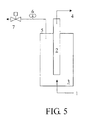
- FIG. 5 An apparatus shown in FIG. 5 was utilized in this example.
- the membrane tube (2) obtained from Example 1 was placed into a shell and tube reactor (3).
- Ar was introduced into the reactor (3) via a gas inlet (1).
- the outside outlet (5) of the membrane tube was opened so the reactor could be filled with Ar.
- the outside outlet (5) was closed to build up a backpressure inside the reactor.
- the inside outlet (4) of the membrane tube was checked if any Ar had permeated through the pores of the membrane tube into the interior thereof.
- the test results showed that no Ar from the reactor (3) had permeated through the membrane tube (2) into the interior thereof. This meant that the membrane tube (2) could withstand an external Ar pressure of 10 absolute atmospheres safely.
- the apparatus shown in FIG. 5 and the membrane tube (2) obtained from Example 1 were used in this example.
- Ar was introduced into the reactor (3) via the gas inlet (1).
- the outside outlet (5) of the membrane tube was opened so that the reactor (3) could be filled with Ar.
- the temperature of the reactor (3) was increased from room temperature to 380°C at a rate of 2.5 °C/min, while the inlet gas was replaced with H 2 of industrial level.
- a regulating valve (7) on the outside outlet (5) was adjusted to maintain a pressure of 5 absolute atmospheres inside the reactor.
- a welded porous stainless steel tube was mechanically polished using sandpaper No. 600, and then was dipped into 10 moles of hydrochloric acid for 3 to 5 minutes and rinsed with deionized water. Subsequently, the resulting tube was immersed into a tin chloride sensitizing solution for 5 minutes, and then was immersed into deionized water for 2 minutes. The tube was then immersed into a palladium chloride activator for 5 minutes and again into deionized water for another 2 minutes.
- Such a cycle was repeated ten times, after which the activated tube was immersed into an electroless plating solution (comprising palladium ammonium chloride and a reducer hydrazine) to obtain a porous stainless steel tube with a palladium membrane prepared by the electroless plating method (referred to as the "electroless-plated palladium membrane tube” hereinafter).
- an electroless plating solution comprising palladium ammonium chloride and a reducer hydrazine
- the operation temperature was increased until the phase change temperature of palladium, i.e., about 250°C to 300°C, was reached.
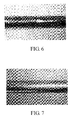
- the electroplated palladium membrane tube of the subject invention was tested again by introducing H 2 to attain a pressure of 3, 5, and 10 absolute atmospheres, respectively. After six hours under the phase change temperature, slow gas leakages were observed in the electroplated palladium membrane tube, but still no chipping occurred, as shown in FIG. 7 .
- the apparatus shown in FIG. 5 and the membrane tube (2) obtained from Example 1 were used in this example.
- the regulating valve (7) on the outside outlet (5) of the membrane tube was adjusted to maintain a normal pressure inside the reactor (3), and a gas mixture comprising 75% of H 2 and 25% of CO 2 was used as the feeding gas to test the H 2 purity which could be obtained by the membrane tube (2).
- the regulating valve (7) on the outside outlet (5) was further adjusted to maintain a pressure of 5 absolute atmospheres inside the reactor (3). Under the resulting pressure differential, H 2 in the reactor (3) permeated through the membrane tube (2) to the inside outlet (4) of the membrane tube.
Landscapes
- Chemical & Material Sciences (AREA)
- Engineering & Computer Science (AREA)
- Chemical Kinetics & Catalysis (AREA)
- Electrochemistry (AREA)
- Materials Engineering (AREA)
- Metallurgy (AREA)
- Organic Chemistry (AREA)
- Electroplating And Plating Baths Therefor (AREA)
- Separation Using Semi-Permeable Membranes (AREA)
Applications Claiming Priority (1)
| Application Number | Priority Date | Filing Date | Title |
|---|---|---|---|
| CN2007100971301A CN101285203B (zh) | 2007-04-13 | 2007-04-13 | 含钯电镀液及其应用 |
Publications (1)
| Publication Number | Publication Date |
|---|---|
| EP1983076A2 true EP1983076A2 (fr) | 2008-10-22 |
Family
ID=39544944
Family Applications (1)
| Application Number | Title | Priority Date | Filing Date |
|---|---|---|---|
| EP07123143A Withdrawn EP1983076A2 (fr) | 2007-04-13 | 2007-12-13 | Solution de placage au palladium et ses utilisations |
Country Status (2)
| Country | Link |
|---|---|
| EP (1) | EP1983076A2 (fr) |
| CN (1) | CN101285203B (fr) |
Families Citing this family (12)
| Publication number | Priority date | Publication date | Assignee | Title |
|---|---|---|---|---|
| CN102120150B (zh) * | 2010-12-08 | 2013-07-03 | 南京工业大学 | 一种齿轮型透氢钯或钯合金膜及氢气分离器 |
| CN102586830B (zh) * | 2011-01-10 | 2015-12-09 | 深圳市奥美特科技有限公司 | 金属丝表面镀金或镀钯的设备及方法 |
| CN102168291B (zh) * | 2011-03-16 | 2013-05-01 | 上海中子星化工科技有限公司 | 一种镀钯液 |
| US8574665B2 (en) * | 2011-06-06 | 2013-11-05 | Xerox Corporation | Palladium precursor composition |
| CN105002535A (zh) * | 2015-08-21 | 2015-10-28 | 无锡桥阳机械制造有限公司 | 一种铜合金电镀液及其电镀方法 |
| CN105401182B (zh) * | 2015-10-14 | 2017-06-23 | 佛山科学技术学院 | 一种在不锈钢上电镀厚钯的镀液配方及其电镀方法 |
| CN105420773A (zh) * | 2015-11-20 | 2016-03-23 | 无锡市嘉邦电力管道厂 | 一种含四苯基溴化锑的钯电镀液及其电镀方法 |
| CN105420772A (zh) * | 2015-11-20 | 2016-03-23 | 无锡市嘉邦电力管道厂 | 一种含四苯基溴化锑的钯电镀液及其电镀方法 |
| CN106179402A (zh) * | 2016-07-21 | 2016-12-07 | 昆明理工大学 | 一种纳米多孔钯催化膜的制备方法 |
| CN107447208B (zh) * | 2017-06-23 | 2020-04-10 | 安庆师范大学 | 一种利用化学镀-置换制备Pd-Ni-Fe-P合金膜的方法 |
| CN107805830A (zh) * | 2017-10-11 | 2018-03-16 | 武汉钢铁有限公司 | 闪镀铁镀液及闪镀方法 |
| CN113005438B (zh) * | 2021-02-23 | 2023-08-22 | 广东工业大学 | 一种银离子促进剂作为提高化学镀钯液中镀钯速率的添加剂的方法 |
Citations (4)
| Publication number | Priority date | Publication date | Assignee | Title |
|---|---|---|---|---|
| US4486274A (en) | 1981-02-27 | 1984-12-04 | At&T Bell Laboratories | Palladium plating prodedure |
| US6152987A (en) | 1997-12-15 | 2000-11-28 | Worcester Polytechnic Institute | Hydrogen gas-extraction module and method of fabrication |
| JP2002119834A (ja) | 2000-10-16 | 2002-04-23 | Mitsubishi Kakoki Kaisha Ltd | 無機水素分離膜の製造方法 |
| JP2002153740A (ja) | 2000-11-21 | 2002-05-28 | Mitsubishi Heavy Ind Ltd | Pd系水素分離膜を製造する方法 |
Family Cites Families (1)
| Publication number | Priority date | Publication date | Assignee | Title |
|---|---|---|---|---|
| US3282737A (en) * | 1962-08-27 | 1966-11-01 | Electric Storage Battery Co | Electrodes and electrode material |
-
2007
- 2007-04-13 CN CN2007100971301A patent/CN101285203B/zh not_active Expired - Fee Related
- 2007-12-13 EP EP07123143A patent/EP1983076A2/fr not_active Withdrawn
Patent Citations (4)
| Publication number | Priority date | Publication date | Assignee | Title |
|---|---|---|---|---|
| US4486274A (en) | 1981-02-27 | 1984-12-04 | At&T Bell Laboratories | Palladium plating prodedure |
| US6152987A (en) | 1997-12-15 | 2000-11-28 | Worcester Polytechnic Institute | Hydrogen gas-extraction module and method of fabrication |
| JP2002119834A (ja) | 2000-10-16 | 2002-04-23 | Mitsubishi Kakoki Kaisha Ltd | 無機水素分離膜の製造方法 |
| JP2002153740A (ja) | 2000-11-21 | 2002-05-28 | Mitsubishi Heavy Ind Ltd | Pd系水素分離膜を製造する方法 |
Non-Patent Citations (7)
| Title |
|---|
| E. NOWICKA ET AL., PROGRESS IN SUIFACE SCIENCE, vol. 48, no. 1-4, 1995, pages 3 - 14 |
| F. A. LEWIS, INT. J. HYDROGEN ENERGY,, vol. 21, no. 6, 1996, pages 461 - 464 |
| JOURNAL OF MEMBRANE SCIENCE, vol. 192, 2001, pages 177 |
| RENOUPREZ, 1 J. F. ET AL., JOURNAL OF CATALYSIS, vol. 170, 1997, pages 181 |
| SEUNG-EUN NAM, JOURNAL OF MEMBRANE SCIENCE, vol. 153, 1999, pages 163 |
| SEUNG-EUN NAM, JOURNAL OF MEMBRANE SCIENCE, vol. 170, 2000, pages 91 |
| TEA-HYUN YANG ET AL., ELECTROCHIMICA ACTA., vol. 41, no. 6, 1996, pages 843 - 844 |
Also Published As
| Publication number | Publication date |
|---|---|
| CN101285203A (zh) | 2008-10-15 |
| CN101285203B (zh) | 2011-04-20 |
Similar Documents
| Publication | Publication Date | Title |
|---|---|---|
| EP1983076A2 (fr) | Solution de placage au palladium et ses utilisations | |
| US6828037B2 (en) | Hydrogen-permeable structure and method for manufacture thereof or repair thereof | |
| CN103945917B (zh) | 渗漏稳定性气体分离膜系统的制备或修复方法 | |
| JP2006520686A (ja) | 中間金属層を有する複合ガス分離モジュール | |
| JP2006520687A (ja) | 複合ガス分離モジュールを製造する方法 | |
| US20080254311A1 (en) | Palladium-containing plating solution and its uses | |
| JP2007535393A (ja) | 複合ガス分離モジュールの製造における欠陥矯正方法 | |
| US20090176012A1 (en) | Unsupported Palladium Alloy Membranes and Methods of Making Same | |
| CN101781760B (zh) | 钯或钯合金复合膜的化学镀修补法 | |
| US20140170328A1 (en) | Electroless plating of ruthenium and ruthenium-plated products | |
| JP5891512B2 (ja) | 多孔性フィルター、その製造方法、多孔性フィルターを支持体とする水素分離膜、欠陥の封止方法、及び水素分離方法 | |
| JPH03288534A (ja) | 無電解Pd―Ag合金メッキ膜を有する水素分離膜及びその製造方法 | |
| JP2003190748A (ja) | ガス分離体の製造方法 | |
| CN109440090B (zh) | 一种硬质合金基底表面化学镀磷化镍-金刚石复合涂层的方法 | |
| JPS62263991A (ja) | 鍍金物製造法 | |
| KR101777361B1 (ko) | 튜브형 또는 원통형 분리막의 무전해 도금 방법 및 이를 위한 도금장치 | |
| JP2004122006A (ja) | 水素分離膜、その製造方法及び水素の分離方法 | |
| JP5311536B2 (ja) | Pd−Agの同時メッキによる水素分離用薄膜の作製方法 | |
| JP6704926B2 (ja) | パラジウム上に金を施したガス分離膜の作製方法 | |
| FR2471426A1 (fr) | Procede d'electrodeposition de palladium et bain electrolytique pour la mise en oeuvre de ce procede | |
| KR102102992B1 (ko) | 세라믹 파우더 유동화를 이용한 도금방법 | |
| CN121250342A (zh) | 一种在镀钛金刚石表面化镀铜的制备方法 | |
| Akis | Preparation of Pd-Ag/PSS Composite Membranes for Hydrogen Separation | |
| KR20060037119A (ko) | 수소기체 분리용 니켈금속막 및 이의 제조방법 | |
| JPH0832962B2 (ja) | 電解用接合体の製造法 |
Legal Events
| Date | Code | Title | Description |
|---|---|---|---|
| PUAI | Public reference made under article 153(3) epc to a published international application that has entered the european phase |
Free format text: ORIGINAL CODE: 0009012 |
|
| AK | Designated contracting states |
Kind code of ref document: A2 Designated state(s): AT BE BG CH CY CZ DE DK EE ES FI FR GB GR HU IE IS IT LI LT LU LV MC MT NL PL PT RO SE SI SK TR |
|
| AX | Request for extension of the european patent |
Extension state: AL BA HR MK RS |
|
| STAA | Information on the status of an ep patent application or granted ep patent |
Free format text: STATUS: THE APPLICATION IS DEEMED TO BE WITHDRAWN |
|
| 18D | Application deemed to be withdrawn |
Effective date: 20130702 |