EP1983133A1 - Ferrure de charnière d'une fenêtre, d'une porte ou analogue, tout comme procédé de montage d'une ferrure de charnière - Google Patents
Ferrure de charnière d'une fenêtre, d'une porte ou analogue, tout comme procédé de montage d'une ferrure de charnière Download PDFInfo
- Publication number
- EP1983133A1 EP1983133A1 EP07007751A EP07007751A EP1983133A1 EP 1983133 A1 EP1983133 A1 EP 1983133A1 EP 07007751 A EP07007751 A EP 07007751A EP 07007751 A EP07007751 A EP 07007751A EP 1983133 A1 EP1983133 A1 EP 1983133A1
- Authority
- EP
- European Patent Office
- Prior art keywords
- insert
- hinge
- bearing pin
- receptacle
- hinge body
- Prior art date
- Legal status (The legal status is an assumption and is not a legal conclusion. Google has not performed a legal analysis and makes no representation as to the accuracy of the status listed.)
- Granted
Links
Images
Classifications
-
- E—FIXED CONSTRUCTIONS
- E05—LOCKS; KEYS; WINDOW OR DOOR FITTINGS; SAFES
- E05D—HINGES OR SUSPENSION DEVICES FOR DOORS, WINDOWS OR WINGS
- E05D15/00—Suspension arrangements for wings
- E05D15/48—Suspension arrangements for wings allowing alternative movements
- E05D15/52—Suspension arrangements for wings allowing alternative movements for opening about a vertical as well as a horizontal axis
- E05D15/5214—Corner supports
-
- E—FIXED CONSTRUCTIONS
- E05—LOCKS; KEYS; WINDOW OR DOOR FITTINGS; SAFES
- E05Y—INDEXING SCHEME ASSOCIATED WITH SUBCLASSES E05D AND E05F, RELATING TO CONSTRUCTION ELEMENTS, ELECTRIC CONTROL, POWER SUPPLY, POWER SIGNAL OR TRANSMISSION, USER INTERFACES, MOUNTING OR COUPLING, DETAILS, ACCESSORIES, AUXILIARY OPERATIONS NOT OTHERWISE PROVIDED FOR, APPLICATION THEREOF
- E05Y2900/00—Application of doors, windows, wings or fittings thereof
- E05Y2900/10—Application of doors, windows, wings or fittings thereof for buildings or parts thereof
- E05Y2900/13—Type of wing
- E05Y2900/132—Doors
-
- E—FIXED CONSTRUCTIONS
- E05—LOCKS; KEYS; WINDOW OR DOOR FITTINGS; SAFES
- E05Y—INDEXING SCHEME ASSOCIATED WITH SUBCLASSES E05D AND E05F, RELATING TO CONSTRUCTION ELEMENTS, ELECTRIC CONTROL, POWER SUPPLY, POWER SIGNAL OR TRANSMISSION, USER INTERFACES, MOUNTING OR COUPLING, DETAILS, ACCESSORIES, AUXILIARY OPERATIONS NOT OTHERWISE PROVIDED FOR, APPLICATION THEREOF
- E05Y2900/00—Application of doors, windows, wings or fittings thereof
- E05Y2900/10—Application of doors, windows, wings or fittings thereof for buildings or parts thereof
- E05Y2900/13—Type of wing
- E05Y2900/148—Windows
Definitions
- the invention relates to a hinge fitting for a window, a door or the like. With a pivotable about a vertical and a horizontal axis on a fixed enclosure, in particular a fixed frame of the window, the door or the like. Wing, in which a bearing pin with a Section at least partially immersed in a surround-side hinge body, wherein the enclosure-side hinge body has an insert which is at least partially disposed in a receptacle of the enclosure-side hinge body.
- the invention also relates to a method for assembling the hinge fitting.
- a hinge fitting for a turn - tilt window having a lower hinge body attached to the frame and an upper hinge body attached to a movable wing.
- a bearing pin is provided which has an upper cylindrical portion, with which it dips into the wing-side hinge body, so that a rotational opening movement of the wing is made possible.
- the bearing pin also has a lower wedge-shaped portion which dips into the lower hinge body, so that a tilt-opening movement of the wing is possible.
- the bearing pin is only inserted in the lower hinge body and can easily fall out of it during transport of the frame with attached lower hinge body.
- From the EP 1 531 226 A2 is a hinge fitting for a about a vertical axis and a horizontal axis pivotally mounted on a window frame or a door wing, wherein a bearing pin for forming the vertical axis at least partially with a cylindrical portion in a wing frame side hinge body dips and on a hinged frame-side hinge body supported, wherein the position pin pivotally immersed about the horizontal axis with a second portion in a receptacle of the hinge body, wherein on the second portion to the first portion radially extending approach is provided, which is associated with a console in the receptacle.
- an insert is arranged, on which the bearing pin is supported.
- the insert is introduced from above into the receptacle together with the bearing pin and can also be removed vertically upwards again. Since hinge fittings are preassembled with frames before the frames are shipped, there is a risk that the bearing pin will slip out of the socket together with the insert. The bearing pin is therefore not reliably held on the lower hinge body.
- Object of the present invention is therefore to provide a hinge fitting, which avoids the disadvantages mentioned above and at the same time is inexpensive to produce with little technical effort.
- a hinge fitting of the type mentioned wherein the insert is at least partially introduced laterally into the receptacle and is overlapped by a hinge body portion at least in sections.
- the overlap preferably causes the insert to be arranged substantially stationary at least in the vertical direction upwards. This measure ensures that the insert can not easily be detached from the hinge body. Especially The insert can not be released from the hinge body in a vertical direction.
- the hinge fitting according to the invention is preferably used in aluminum windows.
- the insert is at least partially introduced from a binding side into the receptacle.
- the insert between the hinge body and a frame to which the hinge body is attached be clamped.
- the insert need not be attached separately to the hinge body.
- the insert is held by this measure reliable and captive on the hinge body.
- the enclosure-side hinge body has in a peripheral side wall at least one passage opening through which an insert part projects into the receptacle. Due to the fact that the insert projects with an insert part through a passage opening, a part of the edge of the passage opening overlaps the insert so that it can be moved in the vertical direction at most due to a clearance.
- the passage opening and the passage opening projecting through the insert part are coordinated so that the insert can not be moved in the vertical direction practically.
- the insert is supported with a contact section from the surround side on the surround-side hinge body.
- an end position is determined, which determines how far the insert can be moved into the receptacle.
- this measure allows for use with a section between the hinge body a frame is trapped.
- the insert is supported by a wall of the hinge body.
- the bearing pin is captively held on the mount-side hinge body by the insert. This ensures that the bearing pin is not lost during transport of the frame with mounted hinge-side hinge body.
- the insert is held captive by its arrangement between the hinge body and frame.
- the bearing pin is in turn held by the insert captive on the hinge body.
- the captive holder can be achieved in a particularly simple manner in that the protruding into the receiving portion of the bearing pin is partially overlapped by the use.
- the bearing pin may have at least one lateral projection which is overlapped by the first insert part.
- the bearing pin has two opposing lateral projections.
- a locking device may be provided by which the bearing pin can be fixed in a transport position.
- the bearing pin can be fixed by the latching device in a vertical position, so that it protrudes as little as possible from the frame. This prevents the bearing pin from being damaged during transport.
- the latching device can be realized in a particularly simple manner in that the at least one projection and the first insert part each have a nose. To engage the noses are moved under appropriate force past each other until the pin assumes a transport position. From the transport position, it can only be moved out again with a certain amount of force. Without additional force noses hold the bearing pin in its transport position.
- one of the noses is a weary nose, this nose wears down over time during operation, so that over time the latch will no longer resist resistance to tilting and closing of the wing.
- the first insert part is fork-shaped and represents a lateral guide for the bearing pin.
- the bearing pin can be arranged between the legs of the fork-shaped insert part and be guided laterally by these legs.
- the insert has a bearing pin alignment device. Due to the wing load, it may happen during operation that the bearing pin is slightly twisted or tilted. To preclude this, the bearing pin is advantageously aligned.
- the Lagerstattausricht can be formed, for example, characterized in that the free space between the legs of the fork-shaped insert to the fork base tapers and the enclosure-side portion of the bearing pin, which projects into the receptacle, at least in the region of the first insert also tapers.
- the insert has a second side in the Recording has projecting insert part on which a bearing cup for the bearing pin is formed.
- the enclosure-side wall of the enclosure-side hinge body has one or more holes.
- the production of the enclosure-side hinge body is particularly cost-effective if the enclosure-side hinge body is formed as an extruded profile.
- the enclosure-side hinge body can be made by cutting an extruded profile.
- the recording is formed vorsprungs- and undercuts. This means that the recording does not need to be reworked after cutting to length.
- no milling tool must be inserted into the receptacle to produce a console, as for example in the enclosure-side hinge bodies as shown in the EP 1531 226 A2 are known, the case is.
- the existing console there must be produced for example by milling, which is very complex to manufacture.
- the receptacle of the hinge body of the hinge fitting according to the invention preferably has exclusively straight, smooth inner walls, wherein unevenness, which may be generated during lateral drilling or milling of the passage openings, are tolerable.
- the production of the hinge fitting according to the invention thus takes place as follows: first, an extruded profile is produced. From this extruded profile several hinge-side hinge body are separated by means of straight cuts the hinge body are cut or sawed off. Subsequently, bores for the insert parts are introduced by drilling from the surround side. Further processing steps of the hinge body are not necessary. When inserting the holes, material can be removed from the inside of the holder. As a result, bumps may arise, but are harmless to the function of the hinge fitting. The recording does not have to be made by milling.
- the scope of the invention also includes a method for assembling a hinge fitting wherein an insert with at least one insert part is first introduced only a little laterally into a receptacle of a hinge-side hinge body, then a bearing pin with a section is inserted into the receptacle and then the insert is pressed into the recording to an end position.
- the insert is first introduced only a little way into the receptacle, so that the bearing pin with its projection or its projections can still be moved past the upper insert part. If the insert is then further pressed in, the first insert part engages over the projections of the bearing pin so that it is held captive in the hinge body via the insert part.
- the hinge body is fastened to an enclosure, in particular a fixed frame, in such a way that a section of the insert comes to rest between the frame and a wall of the enclosure-side hinge body.
- the bearing pin is locked in a transport position.
- the bearing pin is arranged to save space and protected against damage.
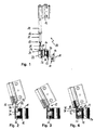
- a hinge fitting 10 is shown in an exploded view.
- the hinge fitting 10 comprises an enclosure-side hinge body 11 and a wing-side hinge body 12. Between the hinge bodies 11,12 Is a bearing pin 13 is provided. On the bearing pin 13, a sleeve 14 can be placed, wherein the sleeve 14 is rotatably mounted on the portion 15 of the bearing pin 13.
- the portion 15 has a flat side 16 which cooperates with a corresponding flat side inside the sleeve 14. Together with the sleeve 14, the portion 15 can be inserted into the hinge body 12, or the hinge body 12 can be placed together with an attached wing on the sleeve 14 and thus the portion 15.
- a rotation of the wing-side hinge body 12 on the sleeve 14 a rotary opening of the wing can be effected by the hinge fitting 12 is rotated about the longitudinal axis of the sleeve 14 relative to the hinge body 11.
- an insert 18 is provided, which can be introduced with a first and a second insert part 19, 20 through openings 21, 22 provided for this purpose in a peripheral wall 23 of the enclosure-side hinge body 11. After inserting the insert 18, the inserts 19,20 protrude into a receptacle 24 into which the portion 25 of the bearing pin 13 can dip.
- the inserts 19,20 When the inserts 19,20 are inserted into the apertures formed as holes 21,22, overlap the web 27 and the Wall section 28, the inserts 19,20, so that the insert 18 is no longer vertically displaceable, in particular not vertically displaced upward. Since the insert 18 is inserted from the surround side in the direction of the arrow 29, this comes with a mounting of the wing-length hinge body 11 to a mount, in particular a fixed frame, between the fixed frame and the enclosure-side hinge body 11 to lie and is characterized without further Attachment to the enclosure-side hinge body 11 is held.
- the completely inserted insert 18 rests with an abutment portion 30 on the housing side on a wall 23.
- the wall 23 is slightly excluded, so that the back of the insert 18 can be completely absorbed and the housing side of the enclosure-side hinge part 11 is an almost step-free contact surface for engagement with a fixed frame is present.
- FIGS. 2 to 5 the assembly process of the bearing pin 13 is shown in the enclosure-side hinge body 11.
- the insert 18 with its inserts 19,20 only partially inserted into the receptacle 24.
- a sufficient space remains between the first insert part 19 and the rear wall 31 of the hinge part 11, so that the section 25 of the bearing pin 13 can be inserted.
- the space between the rear wall 31 and the insert part 19 is necessary so that a lateral projection 32, which is arranged on the section 25, can pass through the upper insert part 19.
- the bearing pin 13 is introduced quasi in a tilted position.
- the free end of the bearing pin 13 is now seated on the second insert part 20, wherein the second insert part 20 forms a bearing socket for the bearing pin 13.
- the insert 18 is completely pressed with the bearing pin 13 seated in the bearing cup.
- the projection 32 comes at least partially below the insert part 19 to lie, so that the projection 32 is overlapped by the insert member 19 and prevents the bearing pin 13 can be removed vertically upwards.
- the bearing pin 13 is thus held captive on the hinge body 11.
- the insert 18 bears against the wall 23 with its contact surface 30.
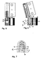
- the first insert part 19 has a nose 35.
- a nose 36 is arranged.
- the bearing pin 13 has been pivoted to a transport position, wherein the lugs 35,36 were moved past each other. This is only possible by using sufficient force.
- the nose 35 prevents the bearing pin 13 is in a tilted position.
- the lugs 35.36 points was a latching device, by the bearing pin 13 can be held in the transport position.
- the bearing pin 13 can be converted into a tilted position, wherein one of the lugs 35,36 is formed so that it wears out over time.
- the hinge fitting according to the invention is in operation for some time and a wing has been closed a few times, one of the tabs 35, 36 is worn so that it no longer presents any appreciable resistance to opening and closing.
- the hinge fitting 10 is shown in a tilt-open position.
- the stop edges 40, 44 do not run parallel. They are aligned so that in an open position, the stop edge 40 extends approximately parallel to the rear wall 31 and extends in a closed position, the stop edge 44 parallel to the vertical. This ensures a large-scale system in both positions.
- the hinge part 19 has two legs 46,47, between which the portion 25 of the bearing pin 13 is arranged.
- the width of the portion 25 is adapted to the gap between the legs 46,47, so that the portion 25 is guided between the legs 46,47.
- the gap between the legs 46, 47 tapers toward the base of the fork 48.
- the portion 25 of the bearing pin 13 tapers.
- its taper is adapted to the taper of the gap.
Landscapes
- Engineering & Computer Science (AREA)
- Mechanical Engineering (AREA)
- Hinges (AREA)
Priority Applications (4)
| Application Number | Priority Date | Filing Date | Title |
|---|---|---|---|
| ES07007751T ES2398372T3 (es) | 2007-04-17 | 2007-04-17 | Herraje de bisagra para ventanas, puertas o similares y su procedimiento de montaje |
| EP07007751A EP1983133B1 (fr) | 2007-04-17 | 2007-04-17 | Ferrure de charnière d'une fenêtre, d'une porte ou analogue, tout comme procédé de montage d'une ferrure de charnière |
| PL07007751T PL1983133T3 (pl) | 2007-04-17 | 2007-04-17 | Okucie zawiasowe okna, drzwi lub tym podobnych oraz sposób montażu okucia zawiasowego |
| CN2008100926419A CN101289913B (zh) | 2007-04-17 | 2008-04-16 | 窗或门的合页配件及用于装配合页配件的方法 |
Applications Claiming Priority (1)
| Application Number | Priority Date | Filing Date | Title |
|---|---|---|---|
| EP07007751A EP1983133B1 (fr) | 2007-04-17 | 2007-04-17 | Ferrure de charnière d'une fenêtre, d'une porte ou analogue, tout comme procédé de montage d'une ferrure de charnière |
Publications (2)
| Publication Number | Publication Date |
|---|---|
| EP1983133A1 true EP1983133A1 (fr) | 2008-10-22 |
| EP1983133B1 EP1983133B1 (fr) | 2012-10-24 |
Family
ID=38519858
Family Applications (1)
| Application Number | Title | Priority Date | Filing Date |
|---|---|---|---|
| EP07007751A Active EP1983133B1 (fr) | 2007-04-17 | 2007-04-17 | Ferrure de charnière d'une fenêtre, d'une porte ou analogue, tout comme procédé de montage d'une ferrure de charnière |
Country Status (4)
| Country | Link |
|---|---|
| EP (1) | EP1983133B1 (fr) |
| CN (1) | CN101289913B (fr) |
| ES (1) | ES2398372T3 (fr) |
| PL (1) | PL1983133T3 (fr) |
Cited By (2)
| Publication number | Priority date | Publication date | Assignee | Title |
|---|---|---|---|---|
| FR3044698A1 (fr) * | 2015-12-07 | 2017-06-09 | Sotralu | Charniere inferieure d'ouvrant oscillo-battant |
| EP4283081A1 (fr) | 2022-05-25 | 2023-11-29 | Roto Frank Fenster- und Türtechnologie GmbH | Ferrure de charnière pour le réglage horizontal des battants d'une fenêtre ou d'une porte |
Citations (5)
| Publication number | Priority date | Publication date | Assignee | Title |
|---|---|---|---|---|
| DE2701979A1 (de) * | 1977-01-19 | 1978-07-20 | Ver Baubeschlag Gretsch Co | Ecklager fuer fensterfluegel |
| DE2703995A1 (de) * | 1977-02-01 | 1978-08-10 | Ver Baubeschlag Gretsch Co | Ecklager fuer fensterfluegel |
| DE4303286A1 (de) * | 1993-02-05 | 1994-08-11 | Bilstein August Gmbh Co Kg | Drehkipp-Ecklager |
| EP1074687A2 (fr) | 1999-08-04 | 2001-02-07 | Euroinvest S.r.L. | Ensemble de charnière pour ferrures de fenêtres oscillo-battantes |
| EP1531226A2 (fr) | 2003-11-13 | 2005-05-18 | Siegenia-Aubi Kg | Ferrure de charnière pour fenêtre ou porte pivotante et basculante |
Family Cites Families (6)
| Publication number | Priority date | Publication date | Assignee | Title |
|---|---|---|---|---|
| DE3503814C2 (de) * | 1985-02-05 | 1996-04-18 | Schuermann & Co Heinz | Drehkipp-Ecklager für Fenster oder Türen, insbesondere für Kunststoffenster oder Kunststofftüren |
| IT1216989B (it) * | 1987-03-18 | 1990-03-14 | Giesse Spa | Cerniera doppia per infissi apribili sia ad anta che a ribalta |
| DE9205399U1 (de) * | 1992-04-18 | 1992-06-17 | Roloff, Heinz-Rudolf, 4150 Krefeld | Scharnierbeschlag für Duschkabinentüren |
| CN1499037A (zh) * | 2002-11-11 | 2004-05-26 | 秦子建 | 电控防盗门的合页 |
| DE20314108U1 (de) * | 2003-09-11 | 2005-01-20 | Dr. Hahn Gmbh & Co. Kg | Band für Türen, Fenster o.dgl. |
| DE202005005777U1 (de) * | 2005-04-11 | 2005-07-07 | Alcamo Ltd. & Co. KG | Beschlag zum Befestigen eines Türflügels |
-
2007
- 2007-04-17 EP EP07007751A patent/EP1983133B1/fr active Active
- 2007-04-17 PL PL07007751T patent/PL1983133T3/pl unknown
- 2007-04-17 ES ES07007751T patent/ES2398372T3/es active Active
-
2008
- 2008-04-16 CN CN2008100926419A patent/CN101289913B/zh not_active Expired - Fee Related
Patent Citations (5)
| Publication number | Priority date | Publication date | Assignee | Title |
|---|---|---|---|---|
| DE2701979A1 (de) * | 1977-01-19 | 1978-07-20 | Ver Baubeschlag Gretsch Co | Ecklager fuer fensterfluegel |
| DE2703995A1 (de) * | 1977-02-01 | 1978-08-10 | Ver Baubeschlag Gretsch Co | Ecklager fuer fensterfluegel |
| DE4303286A1 (de) * | 1993-02-05 | 1994-08-11 | Bilstein August Gmbh Co Kg | Drehkipp-Ecklager |
| EP1074687A2 (fr) | 1999-08-04 | 2001-02-07 | Euroinvest S.r.L. | Ensemble de charnière pour ferrures de fenêtres oscillo-battantes |
| EP1531226A2 (fr) | 2003-11-13 | 2005-05-18 | Siegenia-Aubi Kg | Ferrure de charnière pour fenêtre ou porte pivotante et basculante |
Cited By (3)
| Publication number | Priority date | Publication date | Assignee | Title |
|---|---|---|---|---|
| FR3044698A1 (fr) * | 2015-12-07 | 2017-06-09 | Sotralu | Charniere inferieure d'ouvrant oscillo-battant |
| EP4283081A1 (fr) | 2022-05-25 | 2023-11-29 | Roto Frank Fenster- und Türtechnologie GmbH | Ferrure de charnière pour le réglage horizontal des battants d'une fenêtre ou d'une porte |
| DE102022205247A1 (de) | 2022-05-25 | 2023-11-30 | Roto Frank Fenster- und Türtechnologie GmbH | Scharnierbeschlag zur horizontalen Flügelverstellung eines Fensters oder einer Tür |
Also Published As
| Publication number | Publication date |
|---|---|
| PL1983133T3 (pl) | 2013-03-29 |
| EP1983133B1 (fr) | 2012-10-24 |
| CN101289913A (zh) | 2008-10-22 |
| ES2398372T3 (es) | 2013-03-15 |
| CN101289913B (zh) | 2012-11-21 |
Similar Documents
| Publication | Publication Date | Title |
|---|---|---|
| EP1972743B1 (fr) | Elément de fermeture | |
| EP1437467B1 (fr) | Charnière pour portes ou fenêtres | |
| EP2040948B1 (fr) | Dispositif de liaison pour un élément de retenue d'un capot pour un toit de véhicule automobile pouvant s'ouvrir | |
| EP0711896A2 (fr) | Dispositif de fermeture pour fenêtres, portes ou similaires | |
| EP0128371A2 (fr) | Bras de compas pour porte basculante à bras coulissant et pivotant | |
| EP1983133B1 (fr) | Ferrure de charnière d'une fenêtre, d'une porte ou analogue, tout comme procédé de montage d'une ferrure de charnière | |
| EP0539672B1 (fr) | Ferrure pour fixation dans une rainure d'un profilé rétréci des deux côtés | |
| EP2947221B1 (fr) | Fenêtre de toit et procédé de montage d'une fenêtre de toit | |
| DE3345814C2 (fr) | ||
| EP0698710A1 (fr) | Penture pour portes, fenêtres et similaires | |
| EP2317047B1 (fr) | Agencement de ferrure | |
| EP4146888B1 (fr) | Ensemble charnière à actionnement commun | |
| EP2169167A1 (fr) | Dispositif de réglage de la distance entre deux chariots se déplaçant sur un rail commun et procédé | |
| EP4045744B1 (fr) | Ensemble ferrure | |
| DE102010008597B3 (de) | Tür für einen Geräteschrank | |
| EP1460222B1 (fr) | Charnière pour portes, fenêtres ou similaire | |
| EP2947241A1 (fr) | Serrure à pêne pour un vantail de porte et procédé de montage | |
| DE2904987C2 (de) | Beschlag für Kipp-Schwenkflügel von Fenstern, Türen od. dgl. | |
| EP1979567A1 (fr) | Ensemble charnière permettant une liaison par l'intermédiaire d'une articulation à charnière | |
| EP4048848B1 (fr) | Ensemble de montage | |
| EP0258639B1 (fr) | Palier rotatif avec dispositif de freinage pour un panneau de fenêtre, porte ou similaire | |
| EP1734212B1 (fr) | Ensemble de ferrure | |
| DE19743772B4 (de) | Ausstellvorrichtung mit Haltekörper | |
| DE9207268U1 (de) | Blechschrank | |
| EP1936085B1 (fr) | Armatures pour fenêtres, portes ou analogues |
Legal Events
| Date | Code | Title | Description |
|---|---|---|---|
| PUAI | Public reference made under article 153(3) epc to a published international application that has entered the european phase |
Free format text: ORIGINAL CODE: 0009012 |
|
| AK | Designated contracting states |
Kind code of ref document: A1 Designated state(s): AT BE BG CH CY CZ DE DK EE ES FI FR GB GR HU IE IS IT LI LT LU LV MC MT NL PL PT RO SE SI SK TR |
|
| AX | Request for extension of the european patent |
Extension state: AL BA HR MK RS |
|
| 17P | Request for examination filed |
Effective date: 20081023 |
|
| AKX | Designation fees paid |
Designated state(s): AT BE BG CH CY CZ DE DK EE ES FI FR GB GR HU IE IS IT LI LT LU LV MC MT NL PL PT RO SE SI SK TR |
|
| 17Q | First examination report despatched |
Effective date: 20090924 |
|
| GRAP | Despatch of communication of intention to grant a patent |
Free format text: ORIGINAL CODE: EPIDOSNIGR1 |
|
| GRAS | Grant fee paid |
Free format text: ORIGINAL CODE: EPIDOSNIGR3 |
|
| GRAA | (expected) grant |
Free format text: ORIGINAL CODE: 0009210 |
|
| AK | Designated contracting states |
Kind code of ref document: B1 Designated state(s): AT BE BG CH CY CZ DE DK EE ES FI FR GB GR HU IE IS IT LI LT LU LV MC MT NL PL PT RO SE SI SK TR |
|
| REG | Reference to a national code |
Ref country code: GB Ref legal event code: FG4D Free format text: NOT ENGLISH |
|
| REG | Reference to a national code |
Ref country code: CH Ref legal event code: EP |
|
| REG | Reference to a national code |
Ref country code: AT Ref legal event code: REF Ref document number: 581058 Country of ref document: AT Kind code of ref document: T Effective date: 20121115 |
|
| REG | Reference to a national code |
Ref country code: IE Ref legal event code: FG4D Free format text: LANGUAGE OF EP DOCUMENT: GERMAN |
|
| REG | Reference to a national code |
Ref country code: DE Ref legal event code: R096 Ref document number: 502007010736 Country of ref document: DE Effective date: 20121220 |
|
| REG | Reference to a national code |
Ref country code: ES Ref legal event code: FG2A Ref document number: 2398372 Country of ref document: ES Kind code of ref document: T3 Effective date: 20130315 |
|
| REG | Reference to a national code |
Ref country code: PL Ref legal event code: T3 |
|
| REG | Reference to a national code |
Ref country code: NL Ref legal event code: VDEP Effective date: 20121024 |
|
| PG25 | Lapsed in a contracting state [announced via postgrant information from national office to epo] |
Ref country code: FI Free format text: LAPSE BECAUSE OF FAILURE TO SUBMIT A TRANSLATION OF THE DESCRIPTION OR TO PAY THE FEE WITHIN THE PRESCRIBED TIME-LIMIT Effective date: 20121024 Ref country code: NL Free format text: LAPSE BECAUSE OF FAILURE TO SUBMIT A TRANSLATION OF THE DESCRIPTION OR TO PAY THE FEE WITHIN THE PRESCRIBED TIME-LIMIT Effective date: 20121024 Ref country code: IS Free format text: LAPSE BECAUSE OF FAILURE TO SUBMIT A TRANSLATION OF THE DESCRIPTION OR TO PAY THE FEE WITHIN THE PRESCRIBED TIME-LIMIT Effective date: 20130224 Ref country code: SE Free format text: LAPSE BECAUSE OF FAILURE TO SUBMIT A TRANSLATION OF THE DESCRIPTION OR TO PAY THE FEE WITHIN THE PRESCRIBED TIME-LIMIT Effective date: 20121024 |
|
| PG25 | Lapsed in a contracting state [announced via postgrant information from national office to epo] |
Ref country code: CY Free format text: LAPSE BECAUSE OF FAILURE TO SUBMIT A TRANSLATION OF THE DESCRIPTION OR TO PAY THE FEE WITHIN THE PRESCRIBED TIME-LIMIT Effective date: 20121024 Ref country code: GR Free format text: LAPSE BECAUSE OF FAILURE TO SUBMIT A TRANSLATION OF THE DESCRIPTION OR TO PAY THE FEE WITHIN THE PRESCRIBED TIME-LIMIT Effective date: 20130125 Ref country code: PT Free format text: LAPSE BECAUSE OF FAILURE TO SUBMIT A TRANSLATION OF THE DESCRIPTION OR TO PAY THE FEE WITHIN THE PRESCRIBED TIME-LIMIT Effective date: 20130225 Ref country code: SI Free format text: LAPSE BECAUSE OF FAILURE TO SUBMIT A TRANSLATION OF THE DESCRIPTION OR TO PAY THE FEE WITHIN THE PRESCRIBED TIME-LIMIT Effective date: 20121024 Ref country code: LV Free format text: LAPSE BECAUSE OF FAILURE TO SUBMIT A TRANSLATION OF THE DESCRIPTION OR TO PAY THE FEE WITHIN THE PRESCRIBED TIME-LIMIT Effective date: 20121024 |
|
| PG25 | Lapsed in a contracting state [announced via postgrant information from national office to epo] |
Ref country code: DK Free format text: LAPSE BECAUSE OF FAILURE TO SUBMIT A TRANSLATION OF THE DESCRIPTION OR TO PAY THE FEE WITHIN THE PRESCRIBED TIME-LIMIT Effective date: 20121024 Ref country code: SK Free format text: LAPSE BECAUSE OF FAILURE TO SUBMIT A TRANSLATION OF THE DESCRIPTION OR TO PAY THE FEE WITHIN THE PRESCRIBED TIME-LIMIT Effective date: 20121024 Ref country code: EE Free format text: LAPSE BECAUSE OF FAILURE TO SUBMIT A TRANSLATION OF THE DESCRIPTION OR TO PAY THE FEE WITHIN THE PRESCRIBED TIME-LIMIT Effective date: 20121024 Ref country code: BG Free format text: LAPSE BECAUSE OF FAILURE TO SUBMIT A TRANSLATION OF THE DESCRIPTION OR TO PAY THE FEE WITHIN THE PRESCRIBED TIME-LIMIT Effective date: 20130124 Ref country code: CZ Free format text: LAPSE BECAUSE OF FAILURE TO SUBMIT A TRANSLATION OF THE DESCRIPTION OR TO PAY THE FEE WITHIN THE PRESCRIBED TIME-LIMIT Effective date: 20121024 |
|
| PG25 | Lapsed in a contracting state [announced via postgrant information from national office to epo] |
Ref country code: RO Free format text: LAPSE BECAUSE OF FAILURE TO SUBMIT A TRANSLATION OF THE DESCRIPTION OR TO PAY THE FEE WITHIN THE PRESCRIBED TIME-LIMIT Effective date: 20121024 |
|
| PLBE | No opposition filed within time limit |
Free format text: ORIGINAL CODE: 0009261 |
|
| STAA | Information on the status of an ep patent application or granted ep patent |
Free format text: STATUS: NO OPPOSITION FILED WITHIN TIME LIMIT |
|
| 26N | No opposition filed |
Effective date: 20130725 |
|
| REG | Reference to a national code |
Ref country code: DE Ref legal event code: R097 Ref document number: 502007010736 Country of ref document: DE Effective date: 20130725 |
|
| PG25 | Lapsed in a contracting state [announced via postgrant information from national office to epo] |
Ref country code: MC Free format text: LAPSE BECAUSE OF FAILURE TO SUBMIT A TRANSLATION OF THE DESCRIPTION OR TO PAY THE FEE WITHIN THE PRESCRIBED TIME-LIMIT Effective date: 20121024 |
|
| REG | Reference to a national code |
Ref country code: CH Ref legal event code: PL |
|
| GBPC | Gb: european patent ceased through non-payment of renewal fee |
Effective date: 20130417 |
|
| REG | Reference to a national code |
Ref country code: IE Ref legal event code: MM4A |
|
| PG25 | Lapsed in a contracting state [announced via postgrant information from national office to epo] |
Ref country code: CH Free format text: LAPSE BECAUSE OF NON-PAYMENT OF DUE FEES Effective date: 20130430 Ref country code: LI Free format text: LAPSE BECAUSE OF NON-PAYMENT OF DUE FEES Effective date: 20130430 Ref country code: GB Free format text: LAPSE BECAUSE OF NON-PAYMENT OF DUE FEES Effective date: 20130417 |
|
| PG25 | Lapsed in a contracting state [announced via postgrant information from national office to epo] |
Ref country code: IE Free format text: LAPSE BECAUSE OF NON-PAYMENT OF DUE FEES Effective date: 20130417 |
|
| PG25 | Lapsed in a contracting state [announced via postgrant information from national office to epo] |
Ref country code: LT Free format text: LAPSE BECAUSE OF FAILURE TO SUBMIT A TRANSLATION OF THE DESCRIPTION OR TO PAY THE FEE WITHIN THE PRESCRIBED TIME-LIMIT Effective date: 20121024 |
|
| PG25 | Lapsed in a contracting state [announced via postgrant information from national office to epo] |
Ref country code: MT Free format text: LAPSE BECAUSE OF FAILURE TO SUBMIT A TRANSLATION OF THE DESCRIPTION OR TO PAY THE FEE WITHIN THE PRESCRIBED TIME-LIMIT Effective date: 20121024 |
|
| PG25 | Lapsed in a contracting state [announced via postgrant information from national office to epo] |
Ref country code: LU Free format text: LAPSE BECAUSE OF NON-PAYMENT OF DUE FEES Effective date: 20130417 Ref country code: HU Free format text: LAPSE BECAUSE OF FAILURE TO SUBMIT A TRANSLATION OF THE DESCRIPTION OR TO PAY THE FEE WITHIN THE PRESCRIBED TIME-LIMIT; INVALID AB INITIO Effective date: 20070417 |
|
| REG | Reference to a national code |
Ref country code: FR Ref legal event code: PLFP Year of fee payment: 10 |
|
| REG | Reference to a national code |
Ref country code: FR Ref legal event code: PLFP Year of fee payment: 11 |
|
| PGFP | Annual fee paid to national office [announced via postgrant information from national office to epo] |
Ref country code: AT Payment date: 20170420 Year of fee payment: 11 |
|
| REG | Reference to a national code |
Ref country code: FR Ref legal event code: PLFP Year of fee payment: 12 |
|
| REG | Reference to a national code |
Ref country code: AT Ref legal event code: MM01 Ref document number: 581058 Country of ref document: AT Kind code of ref document: T Effective date: 20180417 |
|
| PG25 | Lapsed in a contracting state [announced via postgrant information from national office to epo] |
Ref country code: AT Free format text: LAPSE BECAUSE OF NON-PAYMENT OF DUE FEES Effective date: 20180417 |
|
| PGFP | Annual fee paid to national office [announced via postgrant information from national office to epo] |
Ref country code: DE Payment date: 20240418 Year of fee payment: 18 |
|
| PGFP | Annual fee paid to national office [announced via postgrant information from national office to epo] |
Ref country code: ES Payment date: 20240517 Year of fee payment: 18 |
|
| PGFP | Annual fee paid to national office [announced via postgrant information from national office to epo] |
Ref country code: IT Payment date: 20240430 Year of fee payment: 18 Ref country code: FR Payment date: 20240419 Year of fee payment: 18 |
|
| PGFP | Annual fee paid to national office [announced via postgrant information from national office to epo] |
Ref country code: PL Payment date: 20240405 Year of fee payment: 18 |
|
| PGFP | Annual fee paid to national office [announced via postgrant information from national office to epo] |
Ref country code: TR Payment date: 20240404 Year of fee payment: 18 Ref country code: BE Payment date: 20240419 Year of fee payment: 18 |
|
| REG | Reference to a national code |
Ref country code: DE Ref legal event code: R119 Ref document number: 502007010736 Country of ref document: DE |
|
| REG | Reference to a national code |
Ref country code: BE Ref legal event code: MM Effective date: 20250430 |
|
| PG25 | Lapsed in a contracting state [announced via postgrant information from national office to epo] |
Ref country code: DE Free format text: LAPSE BECAUSE OF NON-PAYMENT OF DUE FEES Effective date: 20251104 |
|
| PG25 | Lapsed in a contracting state [announced via postgrant information from national office to epo] |
Ref country code: FR Free format text: LAPSE BECAUSE OF NON-PAYMENT OF DUE FEES Effective date: 20250430 |
|
| PG25 | Lapsed in a contracting state [announced via postgrant information from national office to epo] |
Ref country code: BE Free format text: LAPSE BECAUSE OF NON-PAYMENT OF DUE FEES Effective date: 20250430 |
|
| PG25 | Lapsed in a contracting state [announced via postgrant information from national office to epo] |
Ref country code: IT Free format text: LAPSE BECAUSE OF NON-PAYMENT OF DUE FEES Effective date: 20250417 |