EP1983157A1 - Dispositif destiné à étanchéifier un passage organisé d'un élément de perçage dans une bande de joint - Google Patents
Dispositif destiné à étanchéifier un passage organisé d'un élément de perçage dans une bande de joint Download PDFInfo
- Publication number
- EP1983157A1 EP1983157A1 EP07106606A EP07106606A EP1983157A1 EP 1983157 A1 EP1983157 A1 EP 1983157A1 EP 07106606 A EP07106606 A EP 07106606A EP 07106606 A EP07106606 A EP 07106606A EP 1983157 A1 EP1983157 A1 EP 1983157A1
- Authority
- EP
- European Patent Office
- Prior art keywords
- section
- sealing
- shell
- casing
- brim
- Prior art date
- Legal status (The legal status is an assumption and is not a legal conclusion. Google has not performed a legal analysis and makes no representation as to the accuracy of the status listed.)
- Withdrawn
Links
- 238000007789 sealing Methods 0.000 title claims abstract description 16
- 230000035515 penetration Effects 0.000 title description 8
- 239000000463 material Substances 0.000 claims abstract description 15
- 239000012530 fluid Substances 0.000 claims abstract description 12
- 238000010276 construction Methods 0.000 claims description 10
- 230000000149 penetrating effect Effects 0.000 claims description 8
- 239000004567 concrete Substances 0.000 claims description 4
- 239000012528 membrane Substances 0.000 claims description 2
- XLYOFNOQVPJJNP-UHFFFAOYSA-N water Substances O XLYOFNOQVPJJNP-UHFFFAOYSA-N 0.000 description 19
- 239000011378 shotcrete Substances 0.000 description 17
- 239000011435 rock Substances 0.000 description 15
- 239000004800 polyvinyl chloride Substances 0.000 description 10
- 229920000915 polyvinyl chloride Polymers 0.000 description 9
- 239000004698 Polyethylene Substances 0.000 description 3
- 238000011161 development Methods 0.000 description 3
- 230000018109 developmental process Effects 0.000 description 3
- 229920001903 high density polyethylene Polymers 0.000 description 3
- 239000004700 high-density polyethylene Substances 0.000 description 3
- 239000000565 sealant Substances 0.000 description 3
- KQZLRWGGWXJPOS-NLFPWZOASA-N 1-[(1R)-1-(2,4-dichlorophenyl)ethyl]-6-[(4S,5R)-4-[(2S)-2-(hydroxymethyl)pyrrolidin-1-yl]-5-methylcyclohexen-1-yl]pyrazolo[3,4-b]pyrazine-3-carbonitrile Chemical compound ClC1=C(C=CC(=C1)Cl)[C@@H](C)N1N=C(C=2C1=NC(=CN=2)C1=CC[C@@H]([C@@H](C1)C)N1[C@@H](CCC1)CO)C#N KQZLRWGGWXJPOS-NLFPWZOASA-N 0.000 description 2
- 229940125877 compound 31 Drugs 0.000 description 2
- 238000004519 manufacturing process Methods 0.000 description 2
- 241000239290 Araneae Species 0.000 description 1
- 238000004873 anchoring Methods 0.000 description 1
- 230000003466 anti-cipated effect Effects 0.000 description 1
- 230000007797 corrosion Effects 0.000 description 1
- 238000005260 corrosion Methods 0.000 description 1
- 230000003111 delayed effect Effects 0.000 description 1
- 230000001419 dependent effect Effects 0.000 description 1
- 239000003673 groundwater Substances 0.000 description 1
- 238000001746 injection moulding Methods 0.000 description 1
- 238000009434 installation Methods 0.000 description 1
- 230000007774 longterm Effects 0.000 description 1
- 239000004575 stone Substances 0.000 description 1
- 239000000126 substance Substances 0.000 description 1
- 238000004078 waterproofing Methods 0.000 description 1
- 238000003466 welding Methods 0.000 description 1
Images


Classifications
-
- E—FIXED CONSTRUCTIONS
- E21—EARTH OR ROCK DRILLING; MINING
- E21D—SHAFTS; TUNNELS; GALLERIES; LARGE UNDERGROUND CHAMBERS
- E21D11/00—Lining tunnels, galleries or other underground cavities, e.g. large underground chambers; Linings therefor; Making such linings in situ, e.g. by assembling
- E21D11/38—Waterproofing; Heat insulating; Soundproofing; Electric insulating
- E21D11/383—Waterproofing; Heat insulating; Soundproofing; Electric insulating by applying waterproof flexible sheets; Means for fixing the sheets to the tunnel or cavity wall
Definitions
- the present invention relates to a device for sealing a breakthrough element associated breakthrough in a geomembrane in the construction sector.
- the tunnel wall When building a tunnel, the tunnel wall is initially covered on the inside, typically with a geomembrane, to prevent penetration of particular rock water into the tunnel.
- a tensile and shear-resistant anchor system In order to be able to reliably apply shotcrete to the tunnel wall provided with the geomembrane, as desired for creating a shotcrete inner shell, a tensile and shear-resistant anchor system must first be introduced into the tunnel wall. The introduction of such an anchor system has the consequence that the geomembrane is broken at several points of the anchoring of the anchor system inwardly projecting from the tunnel wall and in this anchored. The openings provided in the geomembrane must now in turn be reliably sealed in order to prevent penetration of the rock water between the tunnel wall and the shotcrete inner shell to be produced or into the tunnel itself.
- One of the applicant internally known device for sealing such breakthroughs has a sheath which is provided at its one end with a connecting portion for fluid-tight connection of the device to the geomembrane, wherein the sheath forms a trumpet-like shape together with the connecting portion.
- the device is slipped over the armature section projecting from the tunnel wall covered with the geomembrane, and the connecting section is welded fluid-tight to the geomembrane.
- the shell is pressed by means of clamps fluid-tight to the anchor portion.
- a corresponding sealant between the shell and the anchor portion can be introduced.
- the problem with the described approach is that the measures taken are not completely sufficient to ensure a particularly long-term tightness, as required in tunnel construction. After some time, the rock water can succeed in penetrating between the clamp and the anchor section or past the sealant, in particular at a relatively high water pressure, into the area between the shotcrete inner shell and the geomembrane or into the tunnel itself. This is undesirable because over time this can lead to corrosion of the anchors and also the concrete can be damaged by the leachate over time.
- An object of the present invention is to improve a device for sealing an anchor associated breakthrough in a geomembrane in that a tightness over a longer period and / or at a higher water pressure is ensured.
- a device for sealing a breakthrough element associated with a breakthrough in a geomembrane in the construction sector, in particular in the tunnel construction area.
- the apparatus comprises a shell in which a portion of the penetrating member is receivable, a connecting portion adjacent to the shell for fluid-tightly bonding the device to the sealing web, and at least one brim member extending radially from the shell for deflecting one longitudinally the envelope of flowing fluid, especially rock water, extending away.
- the idea underlying the present invention is to provide an extension of the path which a fluid must travel in order to move from the region from which it emerges from the casing into a region between the shotcrete inner shell and the geomembrane to reach the tunnel interior itself.
- Surrounded by the shotcrete cooperating with this Krempenimplantation cause both the mentioned way extension and a deflection of the fluid. This increases the fluid resistance to be overcome by the fluid and it comes to a backwater of the same. Consequently, increased tightness is achieved by means of the device.
- the at least one brim element is annular.
- a brim element deflects a fluid flow four times by approximately 90 ° each. This ensures a high density.
- the shell has a, substantially annular cross-section. The interior covered by it corresponds to the Substantially the outer shape of the penetrating portion penetrating portion (anchor portion). The sheath can thus be brought into contact with the penetration section (anchor section) in a correspondingly wrinkle-free manner.
- the at least one brim element has a cross-section, which provides a, in the longitudinal direction of the shell widening, in particular linearly widening, edge portion.
- a Krempenelement deflects the fluid flow eight times by about 90 °. Consequently, the tightness can be further increased with such a brim element. Furthermore, the shotcrete adheres better and closer to such a contoured brim element.
- the versetzernde edge portion connects to a web in the radial direction, that is substantially perpendicular to the longitudinal direction of the shell to.
- the edge portion widened at an angle of 15 to 90 ° to the web. Such an angle provides for even better tightness.
- the at least one brim element has at least one recess for receiving concrete, in particular shotcrete.
- the recess, together with the shotcrete, further increases the flow resistance of the fluid.
- the connecting portion is formed in the form of a round, flat disc with a central through hole, wherein the sleeve adjoins an edge region of the through hole and is formed concentrically with the connecting portion.
- the case forms together with the connecting portion of a trumpet-like shape. This is on the one hand good for slipping over the projecting penetration section (anchor section) and on the other hand for a connection of the connecting section to the geomembrane.
- the connecting portion comprises a soft polyvinyl chloride (PVC). Since the geomembranes are typically also formed of soft PVC, a simple and very fluid-tight welding of the connecting portion is made possible with the corresponding region of the geomembrane. Conceivable, of course, would be other materials, such. As PE or the like instead of soft PVC.
- PVC polyvinyl chloride
- the penetrating element is designed as an anchor.
- the device of the invention may of course be provided for use in other applications, such. B. for use in the roof area, z. As a roof skin penetration for antennas, cable connections, lightning protection, etc.
- the at least one brim element and / or the casing has a hard PVC.
- Conceivable of course, would be other materials, such. HDPE instead of hard PVC.
- the device is integrally formed.
- one-piece is to be understood here that the device consists of exactly one part. It is made for this purpose, for example, by injection molding, even using different PVC materials.
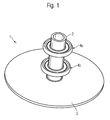
- the Fig. 1-3 show a device 1 according to the invention for sealing an anchor associated breakthrough in a geomembrane in the construction sector.
- the device 1 is composed of a preferably tubular shell 2, a connecting portion 3 and one or more Krempenmaschinen 4a, 4b.
- the shell 2 preferably has an annular cross section and is preferably made of a rigid PVC or HDPE material. At its one end, the shell 2 is integrally connected to the preferably flat, annular connecting portion 3. In this case, the openings of the shell 2 and the connecting portion 3 coincide such that the shell 2 and the connecting portion 3 have a trumpet-like shape.
- a "trumpet-like” is also understood to mean a shape in which the connecting section 3 is in cross-section, see FIG. 3 , is connected at right angles to the shell 2 substantially.
- the connecting portion 3 is preferably made of a soft PVC or PE material.
- the brim elements 4a and 4b are preferably also integrally connected to the shell 2. They are substantially annular in shape and extend in the radial direction to the longitudinal axis 6 of the shell 2. Preferably, the device is rotationally symmetrical, which allows a simpler production thereof and also a better installation.
- the brim elements 4a, 4b have a as in Fig. 3 illustrated cross section 7.
- the cross section 7 is composed of a web 11 and a rim portion 12.
- the edge portion 12 closes in the radial direction away from the longitudinal axis 6 to the web 11, which extends itself in the radial direction to the longitudinal axis 6 at.
- the edge portion 12 widened at an angle 13a, 13b to the web 11.
- the angle 13a or 13b is preferably between 15 and 90 °.
- the brim elements 4a, 4b have on the top side and bottom side, ie pointing away from the connecting section 3 or pointing towards this, a type of dish shape which is bounded by the casing 2 towards the longitudinal axis 6.
- approximately annular recesses 14a and 14b of the Krempenmaschine 4a, 4b are filled in the installed state of the device 1 with shotcrete and contribute to a high flow resistance, as described hereinafter, at.
- Fig. 4 shows the device 1 according to the invention in the installed state.
- a drainage mat 21 In a tunnel wall 20 is a drainage mat 21 and on this in turn a geomembrane 22 is applied.
- an anchor 23 In the tunnel wall, an anchor 23 is fixed at its one end 24.
- a portion 25 of the armature 23 protrudes through an opening 21 a and 22 a in the drainage mat 21 and in the geomembrane 22 therethrough.
- the armature 23 is shown cut off on the left side.
- the section 25 extends into a layer of shotcrete 28, which subsequently, ie after the device 1 is mounted in the position shown, is applied from the inside of the tunnel 29 ago.
- an armature spider (not shown) is mounted at the other end 30 of the armature 23 at the other end 30 of the armature 23, for example, an armature spider (not shown) is mounted.
- the device 1 is slipped over the portion 25 such that the sheath 2 extends along its longitudinal axis 6 along the longitudinal axis 26 of the armature 23.
- the connecting portion 3 rests flat on the sealing sheet 22 and is welded thereto, for example.
- Two clamps 27a, 27b comprise the casing 2 at its periphery and press it against the portion 25. In this case, a largely fluid-tight closure between the casing 2 and the portion 25 is achieved.
- a sealing compound 31 is preferably introduced between the two clamps 27a, 27b. This further improves the seal between the sheath 2 and the fluid penetration section.
- the dashed line 32 represents an anticipated flow of rock water.
- the rock water also succeeds to flow between the casing 2 and the portion 25 in the region of the clamps 27a and 27b and the sealing compound 31 and to flow out of the casing 2 at its tunnel-side end 33 into the shotcrete 28. Then the rock water flow 32 flows along an outer side 34 of the shell 2 and between the shotcrete 28. If the rock water stream 32 hits the Krempenelement 4a, it is deflected by the Krempenelement 4a, which leads to an increase of the flow resistance and thus what further advance the rock water stream 32 impeded or significantly more difficult. Each deflection of the stream of rock water 32 increases the flow resistance to be overcome by this.
- the recesses 14a, 14b filled with the shotcrete 28 contribute to a further increase in the flow resistance.
- the rock-water stream 32 comes to a standstill at the point 35 chosen by way of example, that is, the rock-water stream 32 stops here.
- the point 35 also already further forward, so continue towards the opening 33, or even further back, so closer to the geomembrane 22 lie.
- a penetration of rock water to the geomembrane 22 or to the tunnel interior 29 associated with outlets 36 can thus be prevented or delayed for a very long time.
- the invention is not limited to the specific construction shown in the preceding figures of a device for sealing an aperture associated with an armature in a geomembrane in the construction sector.
- tunnel wall consisting of tunnel wall, waterproofing membrane and shotcrete
- other types of concrete or other building substances can be used in place of the shotcrete.
- rock water can be withheld by the device or its Krempenmaschinen leachate, groundwater or the like.
- the invention is not limited to the above merely exemplary materials such.
Landscapes
- Engineering & Computer Science (AREA)
- Structural Engineering (AREA)
- Mining & Mineral Resources (AREA)
- Architecture (AREA)
- Civil Engineering (AREA)
- Life Sciences & Earth Sciences (AREA)
- General Life Sciences & Earth Sciences (AREA)
- Geochemistry & Mineralogy (AREA)
- Geology (AREA)
- Lining And Supports For Tunnels (AREA)
Priority Applications (1)
| Application Number | Priority Date | Filing Date | Title |
|---|---|---|---|
| EP07106606A EP1983157A1 (fr) | 2007-04-20 | 2007-04-20 | Dispositif destiné à étanchéifier un passage organisé d'un élément de perçage dans une bande de joint |
Applications Claiming Priority (1)
| Application Number | Priority Date | Filing Date | Title |
|---|---|---|---|
| EP07106606A EP1983157A1 (fr) | 2007-04-20 | 2007-04-20 | Dispositif destiné à étanchéifier un passage organisé d'un élément de perçage dans une bande de joint |
Publications (1)
| Publication Number | Publication Date |
|---|---|
| EP1983157A1 true EP1983157A1 (fr) | 2008-10-22 |
Family
ID=38421642
Family Applications (1)
| Application Number | Title | Priority Date | Filing Date |
|---|---|---|---|
| EP07106606A Withdrawn EP1983157A1 (fr) | 2007-04-20 | 2007-04-20 | Dispositif destiné à étanchéifier un passage organisé d'un élément de perçage dans une bande de joint |
Country Status (1)
| Country | Link |
|---|---|
| EP (1) | EP1983157A1 (fr) |
Cited By (2)
| Publication number | Priority date | Publication date | Assignee | Title |
|---|---|---|---|---|
| EP2322722A1 (fr) * | 2009-11-12 | 2011-05-18 | Sika Technology AG | Dispositif destiné à étanchéifier un passage organisé d'un élément de perçage dans une bande de joint |
| EP3059386A1 (fr) * | 2015-02-20 | 2016-08-24 | Ludwig Meese | Corps de fixation |
Citations (5)
| Publication number | Priority date | Publication date | Assignee | Title |
|---|---|---|---|---|
| DE2941684A1 (de) * | 1979-10-15 | 1981-04-23 | Hilti AG, 9494 Schaan | Verfahren zum befestigen einer abdichtungsfolie an einer unterlage |
| DE8424097U1 (de) * | 1984-08-14 | 1985-01-24 | Phoenix Ag, 2100 Hamburg | Gummiprofil |
| EP0275423A2 (fr) * | 1987-01-17 | 1988-07-27 | Werner Schlüter | Profilé rectangulaire en plastique pour l'exécution de joints de dilatation dans des sols ou murs |
| WO2000005487A1 (fr) * | 1998-07-20 | 2000-02-03 | Mbt Holding Ag | Revetement impermeable |
| DE102005048118A1 (de) * | 2005-10-06 | 2007-04-12 | Skumtech As | Spritzbetonbau mit Foliendichtung |
-
2007
- 2007-04-20 EP EP07106606A patent/EP1983157A1/fr not_active Withdrawn
Patent Citations (5)
| Publication number | Priority date | Publication date | Assignee | Title |
|---|---|---|---|---|
| DE2941684A1 (de) * | 1979-10-15 | 1981-04-23 | Hilti AG, 9494 Schaan | Verfahren zum befestigen einer abdichtungsfolie an einer unterlage |
| DE8424097U1 (de) * | 1984-08-14 | 1985-01-24 | Phoenix Ag, 2100 Hamburg | Gummiprofil |
| EP0275423A2 (fr) * | 1987-01-17 | 1988-07-27 | Werner Schlüter | Profilé rectangulaire en plastique pour l'exécution de joints de dilatation dans des sols ou murs |
| WO2000005487A1 (fr) * | 1998-07-20 | 2000-02-03 | Mbt Holding Ag | Revetement impermeable |
| DE102005048118A1 (de) * | 2005-10-06 | 2007-04-12 | Skumtech As | Spritzbetonbau mit Foliendichtung |
Cited By (3)
| Publication number | Priority date | Publication date | Assignee | Title |
|---|---|---|---|---|
| EP2322722A1 (fr) * | 2009-11-12 | 2011-05-18 | Sika Technology AG | Dispositif destiné à étanchéifier un passage organisé d'un élément de perçage dans une bande de joint |
| WO2011057996A1 (fr) * | 2009-11-12 | 2011-05-19 | Sika Technology Ag | Dispositif pour étancher un perçage associé à un élément de perçage dans une bande d'étanchéité |
| EP3059386A1 (fr) * | 2015-02-20 | 2016-08-24 | Ludwig Meese | Corps de fixation |
Similar Documents
| Publication | Publication Date | Title |
|---|---|---|
| DE102007055878A1 (de) | Abdichtelement | |
| DE2707238B2 (de) | Korrosionsgeschütztes Zugglied für einen vorspannbaren Anker im Festgestein | |
| DE20311950U1 (de) | Korrosionsgeschütztes Zugglied, insbesondere Spannglied für Spannbeton | |
| EP2652207B1 (fr) | Elément de coffrage | |
| DE4422648C2 (de) | Sollriß-Fugenschiene | |
| AT504283B1 (de) | Abdichtelement für ein in einem untergrund verankertes befestigungselement | |
| DE102019123868B4 (de) | Durchführungsanordnung und Verwendung einer solchen | |
| EP4397820B1 (fr) | Unité de raccordement pour un drainage de toit comprenant un cadre de raccordement | |
| DE102012110226B4 (de) | Verpressschlauch zum Abdichten von Arbeitsfugen zwischen Bauwerksteilen | |
| EP0190410B1 (fr) | Membrane étanche | |
| DE2441118A1 (de) | Abdichtung an profilbauteilen | |
| DE2553388A1 (de) | Vorgefertigter kanalisationsschacht mit rohranschlusstuecken | |
| EP1696081A1 (fr) | Ancre de fixation | |
| EP1777350B1 (fr) | Gabion pour construction d'une digue | |
| DE9421920U1 (de) | Zwei- oder mehrlagige Kunststoffdichtungsbahn für Bauabdichtungen oder Abdichtungen im Druckwasserbereich | |
| CH683110A5 (de) | Befestigungsanker. | |
| EP3591166B1 (fr) | Soutènement de tunnel composé d'au moins deux éléments en béton | |
| DE10313305B4 (de) | Futterrohr zur Rohrdurchführung durch eine Betonwand | |
| DE202010008496U1 (de) | Schalungs-Abstandhalter und Schalung | |
| EP3199708B1 (fr) | Enceinte de fouille et procédé de fabrication d'une enceinte de fouille | |
| EP2108739B1 (fr) | Système de construction routière pour étanchéifier des joints | |
| EP1741846A1 (fr) | Joint d'étanchéité | |
| WO2011057996A1 (fr) | Dispositif pour étancher un perçage associé à un élément de perçage dans une bande d'étanchéité | |
| DE19838040C2 (de) | Gebäudeanschlußvorrichtung für Versorgungsleitungen | |
| DE2233990C3 (de) | Vorrichtung zur Herstellung eines wenigstens gegen mechanische Kräfte gesicherten Anschlusses einer zur Abdichtung eines Bauwerkes verlegten Dichtungsbahn |
Legal Events
| Date | Code | Title | Description |
|---|---|---|---|
| PUAI | Public reference made under article 153(3) epc to a published international application that has entered the european phase |
Free format text: ORIGINAL CODE: 0009012 |
|
| AK | Designated contracting states |
Kind code of ref document: A1 Designated state(s): AT BE BG CH CY CZ DE DK EE ES FI FR GB GR HU IE IS IT LI LT LU LV MC MT NL PL PT RO SE SI SK TR |
|
| AX | Request for extension of the european patent |
Extension state: AL BA HR MK RS |
|
| 17P | Request for examination filed |
Effective date: 20090422 |
|
| 17Q | First examination report despatched |
Effective date: 20090605 |
|
| AKX | Designation fees paid |
Designated state(s): AT BE BG CH CY CZ DE DK EE ES FI FR GB GR HU IE IS IT LI LT LU LV MC MT NL PL PT RO SE SI SK TR |
|
| GRAP | Despatch of communication of intention to grant a patent |
Free format text: ORIGINAL CODE: EPIDOSNIGR1 |
|
| STAA | Information on the status of an ep patent application or granted ep patent |
Free format text: STATUS: THE APPLICATION IS DEEMED TO BE WITHDRAWN |
|
| 18D | Application deemed to be withdrawn |
Effective date: 20101019 |