EP2652207B1 - Elément de coffrage - Google Patents
Elément de coffrage Download PDFInfo
- Publication number
- EP2652207B1 EP2652207B1 EP20110797008 EP11797008A EP2652207B1 EP 2652207 B1 EP2652207 B1 EP 2652207B1 EP 20110797008 EP20110797008 EP 20110797008 EP 11797008 A EP11797008 A EP 11797008A EP 2652207 B1 EP2652207 B1 EP 2652207B1
- Authority
- EP
- European Patent Office
- Prior art keywords
- hollow
- formwork element
- body formwork
- pile
- layer
- Prior art date
- Legal status (The legal status is an assumption and is not a legal conclusion. Google has not performed a legal analysis and makes no representation as to the accuracy of the status listed.)
- Not-in-force
Links
- 238000009415 formwork Methods 0.000 title claims description 35
- 239000011230 binding agent Substances 0.000 claims description 43
- 229910052500 inorganic mineral Inorganic materials 0.000 claims description 32
- 239000011707 mineral Substances 0.000 claims description 32
- 238000000034 method Methods 0.000 claims description 27
- 239000000565 sealant Substances 0.000 claims description 15
- 239000002131 composite material Substances 0.000 claims description 13
- XLYOFNOQVPJJNP-UHFFFAOYSA-N water Substances O XLYOFNOQVPJJNP-UHFFFAOYSA-N 0.000 claims description 12
- 238000007789 sealing Methods 0.000 claims description 9
- 238000010276 construction Methods 0.000 claims description 5
- 238000002347 injection Methods 0.000 claims description 5
- 239000007924 injection Substances 0.000 claims description 5
- 238000004026 adhesive bonding Methods 0.000 claims description 4
- 229910052751 metal Inorganic materials 0.000 claims description 4
- 239000002184 metal Substances 0.000 claims description 4
- 229920003023 plastic Polymers 0.000 claims description 4
- 239000004033 plastic Substances 0.000 claims description 4
- 239000011148 porous material Substances 0.000 claims description 4
- 238000003466 welding Methods 0.000 claims description 3
- 238000001125 extrusion Methods 0.000 claims description 2
- 230000004888 barrier function Effects 0.000 claims 9
- 238000009416 shuttering Methods 0.000 description 39
- 239000000758 substrate Substances 0.000 description 26
- 239000000835 fiber Substances 0.000 description 12
- 239000000463 material Substances 0.000 description 8
- -1 polyethylene Polymers 0.000 description 8
- 239000004952 Polyamide Substances 0.000 description 6
- 229920001903 high density polyethylene Polymers 0.000 description 6
- 239000004700 high-density polyethylene Substances 0.000 description 6
- 239000007788 liquid Substances 0.000 description 6
- 229920002647 polyamide Polymers 0.000 description 6
- 229920000139 polyethylene terephthalate Polymers 0.000 description 6
- 239000005020 polyethylene terephthalate Substances 0.000 description 6
- 230000008961 swelling Effects 0.000 description 6
- 239000004698 Polyethylene Substances 0.000 description 5
- 229920000573 polyethylene Polymers 0.000 description 5
- 239000000126 substance Substances 0.000 description 5
- 229920002943 EPDM rubber Polymers 0.000 description 4
- 239000002657 fibrous material Substances 0.000 description 4
- 229920001179 medium density polyethylene Polymers 0.000 description 4
- 239000004701 medium-density polyethylene Substances 0.000 description 4
- 229920001169 thermoplastic Polymers 0.000 description 4
- 229920002725 thermoplastic elastomer Polymers 0.000 description 4
- 229920002397 thermoplastic olefin Polymers 0.000 description 4
- 239000004416 thermosoftening plastic Substances 0.000 description 4
- 239000004793 Polystyrene Substances 0.000 description 3
- 239000004567 concrete Substances 0.000 description 3
- 229920001684 low density polyethylene Polymers 0.000 description 3
- 239000004702 low-density polyethylene Substances 0.000 description 3
- 230000035515 penetration Effects 0.000 description 3
- 229920000642 polymer Polymers 0.000 description 3
- 229920002635 polyurethane Polymers 0.000 description 3
- 239000004814 polyurethane Substances 0.000 description 3
- 239000004800 polyvinyl chloride Substances 0.000 description 3
- 229920002994 synthetic fiber Polymers 0.000 description 3
- 239000004831 Hot glue Substances 0.000 description 2
- 239000004743 Polypropylene Substances 0.000 description 2
- 239000004820 Pressure-sensitive adhesive Substances 0.000 description 2
- 150000001252 acrylic acid derivatives Chemical class 0.000 description 2
- 239000004568 cement Substances 0.000 description 2
- 239000003795 chemical substances by application Substances 0.000 description 2
- 238000006073 displacement reaction Methods 0.000 description 2
- 239000005038 ethylene vinyl acetate Substances 0.000 description 2
- 239000004744 fabric Substances 0.000 description 2
- 229920002681 hypalon Polymers 0.000 description 2
- 238000004519 manufacturing process Methods 0.000 description 2
- 239000000203 mixture Substances 0.000 description 2
- 238000000465 moulding Methods 0.000 description 2
- 229920001155 polypropylene Polymers 0.000 description 2
- 238000003825 pressing Methods 0.000 description 2
- 239000003707 silyl modified polymer Substances 0.000 description 2
- 239000012209 synthetic fiber Substances 0.000 description 2
- 239000012815 thermoplastic material Substances 0.000 description 2
- 229920000742 Cotton Polymers 0.000 description 1
- VGGSQFUCUMXWEO-UHFFFAOYSA-N Ethene Chemical compound C=C VGGSQFUCUMXWEO-UHFFFAOYSA-N 0.000 description 1
- 239000005977 Ethylene Substances 0.000 description 1
- 229920000297 Rayon Polymers 0.000 description 1
- 229910000831 Steel Inorganic materials 0.000 description 1
- 238000010521 absorption reaction Methods 0.000 description 1
- 239000000654 additive Substances 0.000 description 1
- 239000000956 alloy Substances 0.000 description 1
- 229910045601 alloy Inorganic materials 0.000 description 1
- 238000004873 anchoring Methods 0.000 description 1
- 229920001400 block copolymer Polymers 0.000 description 1
- 239000004067 bulking agent Substances 0.000 description 1
- 229920005549 butyl rubber Polymers 0.000 description 1
- AXCZMVOFGPJBDE-UHFFFAOYSA-L calcium dihydroxide Chemical compound [OH-].[OH-].[Ca+2] AXCZMVOFGPJBDE-UHFFFAOYSA-L 0.000 description 1
- 239000000920 calcium hydroxide Substances 0.000 description 1
- 229910001861 calcium hydroxide Inorganic materials 0.000 description 1
- 238000005266 casting Methods 0.000 description 1
- 229920002678 cellulose Polymers 0.000 description 1
- 239000001913 cellulose Substances 0.000 description 1
- 239000007795 chemical reaction product Substances 0.000 description 1
- 239000011248 coating agent Substances 0.000 description 1
- 238000000576 coating method Methods 0.000 description 1
- 150000001875 compounds Chemical class 0.000 description 1
- 239000000470 constituent Substances 0.000 description 1
- 229920001577 copolymer Polymers 0.000 description 1
- 238000005336 cracking Methods 0.000 description 1
- 238000005520 cutting process Methods 0.000 description 1
- 230000001419 dependent effect Effects 0.000 description 1
- 238000009826 distribution Methods 0.000 description 1
- 238000005553 drilling Methods 0.000 description 1
- 229920001971 elastomer Polymers 0.000 description 1
- 239000000806 elastomer Substances 0.000 description 1
- 239000003822 epoxy resin Substances 0.000 description 1
- 239000010881 fly ash Substances 0.000 description 1
- 239000011440 grout Substances 0.000 description 1
- 239000011396 hydraulic cement Substances 0.000 description 1
- 239000004572 hydraulic lime Substances 0.000 description 1
- 239000012528 membrane Substances 0.000 description 1
- 230000000149 penetrating effect Effects 0.000 description 1
- 229920000647 polyepoxide Polymers 0.000 description 1
- 229920000728 polyester Polymers 0.000 description 1
- 229920000098 polyolefin Polymers 0.000 description 1
- 239000000047 product Substances 0.000 description 1
- QQONPFPTGQHPMA-UHFFFAOYSA-N propylene Natural products CC=C QQONPFPTGQHPMA-UHFFFAOYSA-N 0.000 description 1
- 125000004805 propylene group Chemical group [H]C([H])([H])C([H])([*:1])C([H])([H])[*:2] 0.000 description 1
- 102000004169 proteins and genes Human genes 0.000 description 1
- 108090000623 proteins and genes Proteins 0.000 description 1
- 229910021487 silica fume Inorganic materials 0.000 description 1
- 239000002893 slag Substances 0.000 description 1
- 239000002689 soil Substances 0.000 description 1
- 239000007787 solid Substances 0.000 description 1
- 238000007711 solidification Methods 0.000 description 1
- 230000008023 solidification Effects 0.000 description 1
- 239000010959 steel Substances 0.000 description 1
- 238000003860 storage Methods 0.000 description 1
- 238000004078 waterproofing Methods 0.000 description 1
- 239000002023 wood Substances 0.000 description 1
Images


Classifications
-
- E—FIXED CONSTRUCTIONS
- E02—HYDRAULIC ENGINEERING; FOUNDATIONS; SOIL SHIFTING
- E02D—FOUNDATIONS; EXCAVATIONS; EMBANKMENTS; UNDERGROUND OR UNDERWATER STRUCTURES
- E02D31/00—Protective arrangements for foundations or foundation structures; Ground foundation measures for protecting the soil or the subsoil water, e.g. preventing or counteracting oil pollution
- E02D31/02—Protective arrangements for foundations or foundation structures; Ground foundation measures for protecting the soil or the subsoil water, e.g. preventing or counteracting oil pollution against ground humidity or ground water
-
- E—FIXED CONSTRUCTIONS
- E02—HYDRAULIC ENGINEERING; FOUNDATIONS; SOIL SHIFTING
- E02D—FOUNDATIONS; EXCAVATIONS; EMBANKMENTS; UNDERGROUND OR UNDERWATER STRUCTURES
- E02D29/00—Independent underground or underwater structures; Retaining walls
- E02D29/16—Arrangement or construction of joints in foundation structures
-
- E—FIXED CONSTRUCTIONS
- E02—HYDRAULIC ENGINEERING; FOUNDATIONS; SOIL SHIFTING
- E02D—FOUNDATIONS; EXCAVATIONS; EMBANKMENTS; UNDERGROUND OR UNDERWATER STRUCTURES
- E02D31/00—Protective arrangements for foundations or foundation structures; Ground foundation measures for protecting the soil or the subsoil water, e.g. preventing or counteracting oil pollution
- E02D31/02—Protective arrangements for foundations or foundation structures; Ground foundation measures for protecting the soil or the subsoil water, e.g. preventing or counteracting oil pollution against ground humidity or ground water
- E02D31/04—Watertight packings for use under hydraulic pressure
Definitions
- the present invention relates to a method for sealing a pile associated with a breakthrough in a geomembrane in the construction sector.
- Bored piles are used, for example, for foundation foundations, especially in soft substrates. For their production, a hole is made with the desired depth and introduced a bored pile in the well or the bored pile immediately driven directly into the ground.
- the substrate When building a concrete structure, the substrate is typically covered with a geomembrane to prevent ingress of water from the subsoil into the structure.
- the bored piles are directly or indirectly connected to the structure, for which the sealing sheet must be pierced. This creates an area in the area of the penetration between the geomembrane and the bored pile, through which moisture from the substrate can enter the building, as can the one out WO 2010/028766 A1 comes out.
- Object of the present invention is therefore to improve a method of the type mentioned in that moisture from the ground is unable to penetrate in the region of the penetration between geomembrane and bored pile.
- the hollow body-shaped formwork element has on the side facing the pile to a contact layer, which has a composite layer of a porous material and / or a sealant.
- FIGS. 1a, 1b and 1c are shown a lateral cross section through a sealed pile according to the inventive method.
- the pile 1 is a pile in the construction area, which is embedded in a substrate 2.
- length, diameter, material, design of the piles can vary.
- the pile is made of materials selected from the group consisting of wood, metal and hardened mineral binders, preferably hardened mineral binders, most preferably concrete.
- Such a pole preferably has a length of 5-25 meters and preferably a diameter of 0.3-2 meters, in particular 0.6-1.2 meters.
- the pile 1 is a bored pile.
- the pile 1 can continue on its the Schott layer 4 facing end support elements 11th have, which, for example, to a wide distribution of the load, respectively anchoring load required.
- the method according to the invention comprises the step 1) of applying a bulkhead layer 4 to the substrate 2.
- the substrate 2 is typically the soil, the substrate may or may not be horizontal, preferably the substrate is substantially horizontal.
- the Schott layer 4 is typically a waterproofing membrane which is suitable for sealing a structure against moisture from the substrate.
- the Schott layer can consist of all materials which ensure sufficient tightness even at high liquid pressures.
- the scotch layer has a high resistance to water pressure, as well as good values in tear propagation and perforation tests.
- the Schott layer is a thermoplastic layer, preferably the Schott layer is selected from the group consisting of high density polyethylene (HDPE), medium density polyethylene (MDPE), low density polyethylene (LDPE), polyethylene (PE), polyethylene terephthalate ( PET), polystyrene (PS), polyvinyl chloride (PVC), polyamides (PA), ethylene-vinyl acetate (EVA), chlorosulfonated polyethylene, thermoplastic polyolefins (TPO), ethylene-propylene-diene rubber (EPDM), and mixtures thereof.
- HDPE high density polyethylene
- MDPE medium density polyethylene
- LDPE low density polyethylene
- PE polyethylene
- PET polyethylene terephthalate
- PS polystyrene
- PVC polyvinyl chloride
- PA polyamides
- EVA ethylene-vinyl acetate
- TPO thermoplastic polyolefins
- EPDM ethylene-propylene-diene rubber
- the Schott layer may have a thickness of 0.1-5 mm, in particular 0.5-3.5 mm, preferably 1.5-2.5 mm.
- the inventive method further comprises the step 2) of the introduction of the pile 1 in the substrate 2. This can be done before or after the step 1).
- the introduction is typically introduced by drilling or piling in the underground. Such methods are known to the person skilled in the art.
- the pile 1 is arranged so as to penetrate the bulkhead layer 4. This can be achieved by piercing the bulkhead layer 4 from the pile when introducing the pile 1 into the substrate 2. However, it can also be achieved that after the introduction of the pile into the ground, the Schott layer is attached to the substrate and the area of the substrate in which the pile is embedded, is left free of Schott layer. This can be achieved, for example, by cutting recesses from the Schott layer in these areas and placing the Schott layer on the substrate in such a way that said recesses come to lie above the pile ends.
- the inventive method comprises the step 3) of attaching a hollow body-shaped shuttering element 3 along the longitudinal center axis of the pile 1, wherein the hollow body-shaped shuttering element surrounds the pile.
- the portion of the pole that is out of the ground will typically be along substantially the entire length, as in FIG. 1 a or 1 c, or only part of its length, as shown in FIG. 1b shown surrounded by the hollow body-shaped shuttering element, preferably along the substantially entire length.
- essentially the entire length is meant in the present case that near the substrate a region of a few centimeters or millimeters along the longitudinal axis of the pile can not be surrounded by the hollow body-shaped shuttering element, for example, when the hollow body-shaped shuttering element is arranged on the Schott layer, as in FIG. 1 a, where in FIG. 1a the pile in the area corresponding to the thickness of the Schott layer is not surrounded by the hollow body-shaped shuttering element.
- the pile can be completely filled with mineral by introducing mineral binder 5 into the intermediate region 12 between the pile and hollow body-shaped formwork element Binder are covered. This is conducive to preventing hindlimbing.
- step 4) the end of the pile 1 facing the Schott layer 4 is substantially completely, in particular completely, covered with mineral binder 5. Furthermore, it may be advantageous to subsequently coat the hardened mineral binder with a layer of epoxy resin and thus to seal it, typically with a layer thickness of 0.5 to 5 cm, preferably 1 to 2 cm. This sealing is suitable both for the case in which the part of the pile, which is located outside the ground, is surrounded substantially along the entire length of the hollow body-shaped shuttering element, as well as for embodiments where this is the case only on a part of its length is.
- the inventive method further comprises the step 4) of introducing mineral binder 5 into the intermediate region 12 between the pile 1 and the hollow body-shaped shuttering element 3.
- the mineral binders are hydraulic binders and / or latently hydraulic binders and / or pozzolanic binders.
- hydraulic binders is understood to mean binders which harden or harden under water, such as, for example, hydraulic lime or cement.
- latent hydraulic binders is understood to mean binders which only set or harden by the action of additives (exciters), such as, for example, granulated blastfurnace slag.
- pozzolanic binders in the present document means binders which do not self-set but after moisture storage by binding of calcium hydroxide provide strength-forming reaction products, such as fly ash, silica fume, and natural pozzolans, such as. B. Trass.
- the mineral binders are typically cement based binders, preferably high strength Grout.
- the introduction is typically done by casting. Such methods are known to the person skilled in the art.
- step 4 in the intermediate region 12 mineral binder remains therein and hardens therein.
- the mineral binder 5 introduced in step 4) essentially bonds firmly to the contact layer 6 and in particular hinders the hollow-body-shaped shuttering element 3 from being traversed by pressurized water 10 of the substrate.
- the contact layer 6 has a composite layer 7 of a porous material and / or a sealant 8.
- the composite layer may consist of all materials, in particular of those which are well penetrated by liquid mineral binders, in particular concrete, and form a good bond with the hardened mineral binder.
- composite layer is understood in this document to mean a layer which can ensure the bond to the applied mineral binder.
- the composite layer may form a substantially solid compound with mineral binders when said mineral binders are contacted with the composite layer prior to their cure.
- the composite layer is made of a porous material.
- a porous structure is conducive to the elasticity of the composite layer, it can better withstand tensile and shear forces. On the other hand, it leads to a good absorption of liquid mineral binders and thus to a good bond with the liquid and the cured mineral binder.
- the composite layer is a fiber material.
- the fibers comprise or consist of organic or synthetic material. In particular, it is cellulose, cotton fibers, protein fibers or synthetic fibers. Fibers made of polyester or of a homo- or copolymers of ethylene and / or propylene or of viscose may be mentioned as synthetic fibers.
- the fibers may here be short fibers or long fibers, spun, woven or non-woven fibers or filaments.
- the fibers may be directional or stretched fibers.
- the fiber material comprises cavities. These cavities are constructed by suitable manufacturing methods. Preferably, the cavities are at least partially open and allow the penetration of liquid mineral binders.
- the body constructed of fibers can be prepared by a variety of methods known to those skilled in the art.
- bodies are used which are a fabric, scrim or knitted fabric.
- a fiber material is a felt or fleece.
- the composite layer is a thermoplastic material and the material is selected from the group comprising high density polyethylene (HDPE), polyethylene terephthalate (PET), polystyrene (PS), polypropylene (PP), polyvinyl chloride (PVC), polyamide (PA) and combinations from that.
- HDPE high density polyethylene
- PET polyethylene terephthalate
- PS polystyrene
- PP polypropylene
- PVC polyvinyl chloride
- PA polyamide
- the composite layer 7 may have a thickness of 0.5 to 30 mm, preferably 2 to 10 mm.
- the sealant is a thermoplastic or a thermoplastic elastomer.
- Thermoplastic elastomers have the advantage that the sealant thereby has a good elasticity against horizontal and vertical displacements, in particular displacements due to mechanical stresses in the structure. A good elasticity of the sealant prevents cracking or detachment of the sealant and thus a failure of the seal.
- thermoplastic elastomers in this document are understood as meaning plastics which combine the mechanical properties of vulcanized elastomers with the processability of thermoplastics.
- thermoplastic elastomers are block copolymers with hard and soft segments or so-called polymer alloys with correspondingly thermoplastic and elastomeric constituents.
- sealants which are selected from the group consisting of acrylate compounds, polyurethane polymers, silane-terminated polymers and polyolefins.
- the sealant 8 is a pressure-sensitive adhesive and / or a hotmelt adhesive. This ensures a good bond and good adhesion between the mineral binder and the hollow body formwork element and thus reduces the detachment of the sealant and thus a failure of the seal.
- Pressure-sensitive adhesives and hot melt adhesives are generally known to the person skilled in the art and are described in CD Römpp Chemie Lexikon, Version 1.0, Georg Thieme Verlag, Stuttgart.
- the sealant contains swelling agents which upon contact with water increase their volume to a multiple, typically between 200-1000% of the original volume.
- certain swelling substances can also react chemically with water.
- swelling agents are polyurethane-based bulking agents, in particular silane-modified polymers which cure by moisture to give an elastic product.
- swelling substances are bentonite-butyl rubbers.
- the swellable substances are swelling substances which react with water in a time-delayed manner by coating, so that the swelling substances do not swell or only swell during contact with moist mineral binders and are swellable in the event of running behind the hollow body-shaped sealing element with pressing water stay.
- the sealant may have a thickness of 0.5 to 30 mm, preferably 2 to 10 mm.
- the hollow body-shaped shuttering element 3 has at least one injection hose which is arranged on the side of the hollow body-shaped shuttering element 3 facing the pile 1.
- suitable injection materials such as acrylate compounds, polyurethane polymers or cement after the hardening of the mineral binder can be subsequently introduced by the injection hose and thus limit hindrance, especially prevent.
- the hollow body-shaped shuttering element 3 may further comprise a support layer 9 made of metal, in particular steel, or a plastic, in particular a thermoplastic material, which is selected from the group consisting of high density polyethylene (HDPE), medium density polyethylene (MDPE), polyethylene low density (LDPE), polyethylene (PE), polyethylene terephthalate (PET), polystyrene (PS), polyvinyl chloride (PVC), polyamides (PA), ethylene-vinyl acetate (EVA), chlorosulfonated polyethylene, thermoplastic polyolefins (TPO) and ethylene Propylene-diene rubber (EPDM).
- HDPE high density polyethylene
- MDPE medium density polyethylene
- LDPE polyethylene low density
- PE polyethylene
- PET polyethylene terephthalate
- PS polystyrene
- PVC polyvinyl chloride
- PA polyamides
- EVA ethylene-vinyl acetate
- TPO thermoplastic polyolefins
- the support layer 9 has a thickness of 0.2 - 5 mm, in the case that it is a metal support layer in particular of 0.6 - 2 mm, in the case that it is a plastic support layer is in particular from 0.5 to 5 mm ,
- the hollow body-shaped shuttering element 3 is not substantially bulged or bent, in particular not bulged or bent. This is to the advantage of advantage, because a controlled filling level and dimension of filled with mineral binder formwork element can be ensured. Further damage to the formwork element is prevented by the forces resulting from the weight of the binder forces.
- the hollow body-shaped shuttering element 3 has a height of 2 to 50 cm, in particular 5 to 30 cm.
- the hollow body-shaped shuttering element 3 can be arranged substantially on the side facing away from the substrate 2 side of the Schott layer 4, as shown in the FIGS. 1a and 1b is apparent or not.
- the hollow body-shaped shuttering element can also be arranged on the side facing away from the substrate 2 and facing side of the Schott layer 4, as shown in the Figure 1c will be shown.
- the hollow body-shaped shuttering element 3 is arranged substantially on the side facing away from the substrate 2 side of the Schott layer 4.
- substantially on the side facing away from the substrate side of the Schott layer is understood in the present case that more than 80%, preferably more than 90%, particularly preferably more than 95%, of the height of the hollow body-shaped shuttering element on the side facing away from the substrate 2 the Schott layer 4 is arranged. It is further preferred if the hollow body-shaped shuttering element 3 is arranged completely on the side facing away from the substrate 2 side of the Schott layer 4.
- the method according to the invention comprises the step 5) of connecting the Schott layer 4 and the hollow-body-shaped shuttering element 3.
- the connection can be made in any manner which has an in the Ensures substantially watertight connection between the Schott layer 4 and hollow body-shaped shuttering element 3.
- the connection is effected by welding and / or gluing and / or mechanical connection.
- Step 5) may be performed before or after step 4).
- step 5) is performed after step 4).
- the hollow body-shaped shuttering element has at least one connecting element 13, which connects the hollow body-shaped shuttering element 3 with the Schott layer 4, as shown in FIGS FIGS. 1 a and 1 b is shown.
- the connecting element is preferably a band which surrounds the hollow body-shaped formwork element and which is attached radially outward.
- the tape typically has a width of 2 - 50 cm, in particular 5 - 30 cm, and a thickness of 0.2 - 5 mm.
- step 5 the bonding of the Schott layer 4 and the hollow body-shaped shuttering element 3 is carried out by welding and / or gluing and / or mechanically connecting the connecting element 13 and the Schott layer 4.
- bonding results in an overlap area of connector and bulkhead of 2-15 cm.
- the connecting element is arranged on the side facing the Schott layer edge of the hollow body-shaped shuttering element, as for example in the FIGS. 1 a and 1 b can be seen.
- the hollow body-shaped shuttering element 3 is preferably a hollow body with two openings, in particular a cylindrical hollow body, in particular preferably a substantially circular-cylindrical hollow body, most preferably a circular-cylindrical hollow body.
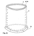
- the hollow body-shaped shuttering element 3 is a hollow body produced by deep-drawing or extrusion, as shown in FIG. 2 is shown, or a curved planar body which overlaps in its longitudinal direction.
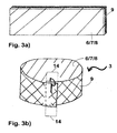
- FIG. 3a shows a possible flat body, or FIG. 3b after molding to a hollow body-shaped shuttering element lateral overlap with itself.
- the flat body can be connected to itself in various ways in the overlapping region 14 to form a hollow body, for example by gluing or mechanical connection means.
- the overlapping area is secured with at least one clip-shaped holding element, as shown in FIG FIG. 3b is shown.
- the overlapping area 14 is 2 - 30 cm, measured from the axial longitudinal edges in the longitudinal direction along the flat body.
Landscapes
- Engineering & Computer Science (AREA)
- Life Sciences & Earth Sciences (AREA)
- Structural Engineering (AREA)
- Environmental & Geological Engineering (AREA)
- General Life Sciences & Earth Sciences (AREA)
- Mining & Mineral Resources (AREA)
- Paleontology (AREA)
- Civil Engineering (AREA)
- General Engineering & Computer Science (AREA)
- Hydrology & Water Resources (AREA)
- Forms Removed On Construction Sites Or Auxiliary Members Thereof (AREA)
- Piles And Underground Anchors (AREA)
Claims (12)
- Procédé de scellement de poteaux (1) dans des fondations (2) dans le domaine de la construction par emploi d'un élément de coffrage à corps creux (3), comprenant les étapes suivantes :1) l'application d'une couche barrière (4) à la fondation (2);2) l'introduction d'un poteau (1) dans la fondation (2), le poteau (1) étant disposé de manière à pénétrer dans la couche barrière (2) ;3) l'application d'un élément de coffrage à corps creux (3) le long de l'axe central longitudinal du poteau (1), l'élément de coffrage à corps creux (3) entourant le poteau 1;4) l'introduction d'agents minéraux de liaison (5) dans l'espace intermédiaire (12) entre le poteau (1) et l'élément de coffrage à corps creux (3) ;5) le raccordement de la couche barrière (4) et de l'élément de coffrage à corps creux (3) ;dans lequel l'élément de coffrage à corps creux (3) a sur le côté orienté vers le poteau (1) une couche de contact (6) qui comprend une couche composite (7) d'un matériau poreux et/ou d'un enduit étanche (8).
- Procédé selon la revendication 1, caractérisé en ce que l'élément de coffrage à corps creux (3) est disposé surtout sur le côté de la couche barrière (4) à l'écart de la fondation (2).
- Procédé selon la revendication 1 ou 2, caractérisé en ce qu'à l'étape 4), l'extrémité du poteau (1) faisant face à la couche barrière (4) est recouvert pratiquement complètement d'un liant minéral (5).
- Procédé selon l'une des revendications précédentes, caractérisé en ce que pendant ou après l'étape 4), l'élément de coffrage à corps creux (3) est essentiellement non incurvé ou courbé.
- Procédé selon l'une des revendications précédentes, caractérisé en ce que l'élément de coffrage à corps creux (3) comporte une couche de soutien (9) de métal ou d'une matière plastique, l'épaisseur de la couche de soutien (9) étant de préférence comprise entre 0,2 et 5 mm.
- Procédé selon l'une des revendications précédentes, caractérisé en ce que l'élément de coffrage à corps creux (3) a une hauteur comprise entre 2 et 50 cm.
- Procédé selon l'une des revendications précédentes, caractérisé en ce que l'élément de coffrage à corps creux (3) n'est pas retiré après le durcissement du liant minéral introduit à l'étape 4).
- Procédé selon l'une des revendications précédentes, caractérisé en ce que le liant minéral (5) introduit à l'étape 4) est sensiblement lié fermement à la couche de contact (6) et en particulier, il empêche l'eau d'infiltration (10) de la fondation d'aller derrière l'élément de coffrage à corps creux (3).
- Procédé selon l'une des revendications précédentes, caractérisé en ce que l'élément de coffrage à corps creux (3) est un corps creux cylindrique.
- Procédé selon l'une des revendications précédentes, caractérisé en ce que l'élément de coffrage à corps creux (3) ;
est un corps creux obtenu par emboutissage ou par extrusion, ou
un corps incurvé en forme de feuille, qui recouvre dans sa direction longitudinale, la région de recouvrement étant de préférence fixée avec au moins un élément de rétention de type pince, et en outre de préférence, la région de recouvrement (14) mesure de 2 à 30 cm, mesurés à partir des bords de longueur axiale dans la direction longitudinale le long du corps en forme de feuille. - Procédé selon l'une des revendications précédentes, caractérisé en ce que l'élément de coffrage à corps creux (3) comporte au moins un élément de raccordement (13), qui est de préférence disposé au bord de l'élément de coffrage à corps creux (3) faisant face à la couche barrière (4), et qui raccorde l'élément de coffrage à corps creux (3) à la couche barrière (4), de préférence à l'étape 5), le raccordement de la couche barrière (4) et de l'élément de coffrage à corps creux (3) se fait par soudage et/ou collage et/ou jonction mécanique de l'élément de raccordement (13) et de la couche barrière (4).
- Procédé selon l'une des revendications précédentes, caractérisé en ce que l'élément de coffrage à corps creux (3) comporte au moins un tuyau souple d'injection, qui est disposé sur le côté de l'élément de coffrage à corps creux (3) faisant face au poteau (1).
Priority Applications (1)
| Application Number | Priority Date | Filing Date | Title |
|---|---|---|---|
| EP20110797008 EP2652207B1 (fr) | 2010-12-17 | 2011-12-14 | Elément de coffrage |
Applications Claiming Priority (3)
| Application Number | Priority Date | Filing Date | Title |
|---|---|---|---|
| EP20100195626 EP2466013A1 (fr) | 2010-12-17 | 2010-12-17 | Elément de coffrage |
| EP20110797008 EP2652207B1 (fr) | 2010-12-17 | 2011-12-14 | Elément de coffrage |
| PCT/EP2011/072766 WO2012080341A1 (fr) | 2010-12-17 | 2011-12-14 | Élément de coffrage |
Publications (2)
| Publication Number | Publication Date |
|---|---|
| EP2652207A1 EP2652207A1 (fr) | 2013-10-23 |
| EP2652207B1 true EP2652207B1 (fr) | 2015-04-08 |
Family
ID=43796150
Family Applications (2)
| Application Number | Title | Priority Date | Filing Date |
|---|---|---|---|
| EP20100195626 Withdrawn EP2466013A1 (fr) | 2010-12-17 | 2010-12-17 | Elément de coffrage |
| EP20110797008 Not-in-force EP2652207B1 (fr) | 2010-12-17 | 2011-12-14 | Elément de coffrage |
Family Applications Before (1)
| Application Number | Title | Priority Date | Filing Date |
|---|---|---|---|
| EP20100195626 Withdrawn EP2466013A1 (fr) | 2010-12-17 | 2010-12-17 | Elément de coffrage |
Country Status (7)
| Country | Link |
|---|---|
| US (1) | US9127433B2 (fr) |
| EP (2) | EP2466013A1 (fr) |
| JP (1) | JP5960715B2 (fr) |
| CN (1) | CN103228845B (fr) |
| BR (1) | BR112013011368A2 (fr) |
| RU (1) | RU2581066C2 (fr) |
| WO (1) | WO2012080341A1 (fr) |
Families Citing this family (6)
| Publication number | Priority date | Publication date | Assignee | Title |
|---|---|---|---|---|
| CN103821180B (zh) * | 2014-03-02 | 2015-07-29 | 山东交通学院 | 一种混凝土伸缩缝双止水结构 |
| CN104727349B (zh) * | 2014-03-02 | 2016-12-07 | 宁波市鄞州丰茂水利工程有限公司 | 一种混凝土伸缩缝双止水结构固定件 |
| EP3909932A1 (fr) * | 2015-12-23 | 2021-11-17 | Sika Technology AG | Couche de contact avec un composant de charge solide |
| CN205742241U (zh) * | 2016-06-28 | 2016-11-30 | 广东中科华大工程技术检测有限公司 | 一种钢管灌注预应力稳压封桩装置 |
| CN108589797B (zh) * | 2018-06-06 | 2023-12-05 | 中铁第四勘察设计院集团有限公司 | 一种地下结构与墩柱分离式节点防水系统 |
| CN115369927A (zh) * | 2022-09-13 | 2022-11-22 | 中国三冶集团有限公司 | 一种垃圾坑底板桩头防渗结构施工方法 |
Family Cites Families (29)
| Publication number | Priority date | Publication date | Assignee | Title |
|---|---|---|---|---|
| US892592A (en) * | 1905-10-17 | 1908-07-07 | E G Siggers | Post and tile mold. |
| US1409422A (en) * | 1921-03-17 | 1922-03-14 | Harry E Squire | Process for producing composite piles |
| US2428070A (en) * | 1945-11-29 | 1947-09-30 | Frenkil Victor | Foundation pile |
| US3166871A (en) * | 1962-02-23 | 1965-01-26 | P L Montemurro | Apparatus for setting a fence post in concrete |
| DE2147051A1 (de) * | 1971-09-21 | 1973-04-05 | Dyckerhoff & Widmann Ag | Verfahren zum herstellen eines druckpfahles im boden |
| US4019301A (en) * | 1974-07-15 | 1977-04-26 | Fox Douglas L | Corrosion-resistant encasement for structural members |
| DE2734525A1 (de) * | 1977-07-30 | 1979-02-08 | Dynamit Nobel Ag | Randbefestigung von kunststoffdichtungsbahnen an einem bauwerk |
| JPS6030485Y2 (ja) * | 1982-08-14 | 1985-09-12 | 藤森工業株式会社 | 固定部材打込用部材 |
| JPH0126891Y2 (fr) * | 1985-05-31 | 1989-08-11 | ||
| US4767095A (en) * | 1986-12-23 | 1988-08-30 | Fitzgerald John M | Concrete column form |
| US5175973A (en) * | 1988-06-14 | 1993-01-05 | Team, Inc. | Compression repair method and apparatus |
| RU2057847C1 (ru) * | 1992-09-15 | 1996-04-10 | Александр Сергеевич Петрашень | Способ усиления фундаментов |
| JP3192277B2 (ja) * | 1993-05-14 | 2001-07-23 | 新日本製鐵株式会社 | コンクリート柱 |
| US6471446B2 (en) * | 1996-12-02 | 2002-10-29 | Foundation Technologies, Inc. | Reduced skin friction bore casing |
| US5915884A (en) * | 1996-12-11 | 1999-06-29 | Surevoid Products, Inc. | Arcuate end corrugated paper form void |
| US5890844A (en) * | 1997-10-08 | 1999-04-06 | Schellhorn; Verne L. | Single engine soil processing system |
| JPH11315587A (ja) * | 1998-05-01 | 1999-11-16 | Taiheiyo Cement Corp | 構造物の防食被覆構造、防食工法および防食パネル |
| JP4063690B2 (ja) * | 2003-03-03 | 2008-03-19 | 鹿島建設株式会社 | 被覆型廃棄物最終処分場の構造物の遮水工法及びその構造 |
| JP2005194768A (ja) * | 2004-01-07 | 2005-07-21 | Murata Mach Ltd | コンクリート柱補修および/又は補強工法及び補修および/又は補強部材 |
| US7192219B2 (en) * | 2005-03-22 | 2007-03-20 | Dominick Graziosi | Pier boot and method for sealing a crawlspace |
| RU2305154C1 (ru) * | 2006-01-30 | 2007-08-27 | ГОУ ВПО "Санкт-Петербургский государственный архитектурно-строительный университет" | Способ возведения плитно-свайного фундамента |
| DE102006059044A1 (de) * | 2006-12-14 | 2008-06-19 | Fischerwerke Gmbh & Co. Kg | Verfahren und Anordnung zum Abdichten von Gebäuden |
| RU2385384C1 (ru) * | 2008-07-18 | 2010-03-27 | Общество с ограниченной ответственностью "МПО РИТА" | Способ изготовления узла сопряжения сваи с существующим фундаментом при его усилении (варианты) |
| RU2378454C1 (ru) * | 2008-08-14 | 2010-01-10 | Федеральное государственное образовательное учреждение высшего профессионального образования Кубанский государственный аграрный университет | Способ возведения свайно-плитного фундамента |
| IT1392652B1 (it) | 2008-09-11 | 2012-03-16 | Carpi Tech Bv Amsterdam Chiasso Branch | Metodo e sistema per il fissaggio di membrane impermeabili ad opere idrauliche |
| EP2177349A1 (fr) * | 2008-10-15 | 2010-04-21 | Sika Technology AG | Membrane étanche à l'eau |
| US8192111B2 (en) * | 2009-05-20 | 2012-06-05 | Gse Lining Technology, Inc. | Boot for geosynthetic layer |
| CN101691739B (zh) * | 2009-08-31 | 2011-04-20 | 天津市水利科学研究院 | 复合型自粘止水带及制作方法和施工方法 |
| CN101781885A (zh) * | 2010-03-12 | 2010-07-21 | 中国水电顾问集团中南勘测设计研究院 | 复合橡胶止水带以及贴坡式止水结构 |
-
2010
- 2010-12-17 EP EP20100195626 patent/EP2466013A1/fr not_active Withdrawn
-
2011
- 2011-12-14 RU RU2013117937/03A patent/RU2581066C2/ru not_active IP Right Cessation
- 2011-12-14 JP JP2013543760A patent/JP5960715B2/ja not_active Expired - Fee Related
- 2011-12-14 WO PCT/EP2011/072766 patent/WO2012080341A1/fr not_active Ceased
- 2011-12-14 CN CN201180057481.4A patent/CN103228845B/zh not_active Expired - Fee Related
- 2011-12-14 BR BR112013011368A patent/BR112013011368A2/pt not_active Application Discontinuation
- 2011-12-14 EP EP20110797008 patent/EP2652207B1/fr not_active Not-in-force
-
2013
- 2013-06-14 US US13/918,231 patent/US9127433B2/en not_active Expired - Fee Related
Also Published As
| Publication number | Publication date |
|---|---|
| EP2466013A1 (fr) | 2012-06-20 |
| RU2581066C2 (ru) | 2016-04-10 |
| US20130279991A1 (en) | 2013-10-24 |
| JP5960715B2 (ja) | 2016-08-02 |
| WO2012080341A1 (fr) | 2012-06-21 |
| CN103228845A (zh) | 2013-07-31 |
| JP2014501341A (ja) | 2014-01-20 |
| BR112013011368A2 (pt) | 2017-07-25 |
| CN103228845B (zh) | 2015-09-23 |
| EP2652207A1 (fr) | 2013-10-23 |
| US9127433B2 (en) | 2015-09-08 |
| RU2013117937A (ru) | 2015-01-27 |
Similar Documents
| Publication | Publication Date | Title |
|---|---|---|
| EP2349707B1 (fr) | Membrane étanche à l'eau | |
| EP2652207B1 (fr) | Elément de coffrage | |
| EP2480725B1 (fr) | Membrane étanche à l'eau | |
| EP2756168A1 (fr) | Élément de cuvelage avec couche d'étanchéité thermoplastique | |
| DE102016107632A1 (de) | Platten- oder bahnförmige Dichtung für Bauwerke aus Beton sowie Verfahren zum Herstellen einer Verbundabdichtung im Wand-, Boden- und Deckenbereich von Bauwerken aus Materialien auf Zementbasis, insbesondere Beton | |
| DE4428591C2 (de) | Zwei- oder mehrlagige Kunststoffdichtungsbahn, Verfahren zum Abdichten von Bauten oder Bauwerksteilen mit einer Kunststoffdichtungsbahn sowie Verwendung derselben | |
| EP2093339B1 (fr) | Dispositif de fixation d'un joint sur une plaque de coffrage | |
| JP2015224470A (ja) | 盛土の安定化工法 | |
| EP2949462B1 (fr) | Élément d'étanchéité de surface pour corps de construction | |
| DE2607317B2 (de) | Rohrformstück | |
| DE9421920U1 (de) | Zwei- oder mehrlagige Kunststoffdichtungsbahn für Bauabdichtungen oder Abdichtungen im Druckwasserbereich | |
| DE2400866A1 (de) | Ausbau fuer unterirdische raeume, insbesondere im tunnel- und im untertagebergbau, z.b. zum streckenausbau | |
| DE102004055488B4 (de) | Schichtaufbau | |
| DE102021004465A1 (de) | Schwindrohrschuh zur zuverlässigen Stabilisierung und Verbindung der Ausrichtung eines Schwindrohres mit einem Fugenband | |
| EP1983157A1 (fr) | Dispositif destiné à étanchéifier un passage organisé d'un élément de perçage dans une bande de joint | |
| EP2945785A1 (fr) | Procédé de fabrication d'un segment de cuvelage muni d'une couche barrière thermoplastique | |
| EP0048959A2 (fr) | Elément de fondation, pouvant supporter des charges, particulièrement en béton armé | |
| EP3854952A1 (fr) | Procédé de construction d'une construction enterrée | |
| DE2233990C3 (de) | Vorrichtung zur Herstellung eines wenigstens gegen mechanische Kräfte gesicherten Anschlusses einer zur Abdichtung eines Bauwerkes verlegten Dichtungsbahn | |
| WO2011057996A1 (fr) | Dispositif pour étancher un perçage associé à un élément de perçage dans une bande d'étanchéité | |
| DE9408760U1 (de) | Zwei- oder mehrlagige Kunststoffbahn | |
| DE202004020399U1 (de) | Schichtaufbau | |
| DE202010006962U1 (de) | Entwässerungsrinne | |
| WO2017152890A1 (fr) | Paroi de retenue |
Legal Events
| Date | Code | Title | Description |
|---|---|---|---|
| PUAI | Public reference made under article 153(3) epc to a published international application that has entered the european phase |
Free format text: ORIGINAL CODE: 0009012 |
|
| 17P | Request for examination filed |
Effective date: 20130717 |
|
| AK | Designated contracting states |
Kind code of ref document: A1 Designated state(s): AL AT BE BG CH CY CZ DE DK EE ES FI FR GB GR HR HU IE IS IT LI LT LU LV MC MK MT NL NO PL PT RO RS SE SI SK SM TR |
|
| RIN1 | Information on inventor provided before grant (corrected) |
Inventor name: KLOSTER, MAGNUS Inventor name: MEYER, KLAUS Inventor name: WEBER, ULRICH K. |
|
| DAX | Request for extension of the european patent (deleted) | ||
| GRAP | Despatch of communication of intention to grant a patent |
Free format text: ORIGINAL CODE: EPIDOSNIGR1 |
|
| INTG | Intention to grant announced |
Effective date: 20141027 |
|
| GRAS | Grant fee paid |
Free format text: ORIGINAL CODE: EPIDOSNIGR3 |
|
| GRAA | (expected) grant |
Free format text: ORIGINAL CODE: 0009210 |
|
| AK | Designated contracting states |
Kind code of ref document: B1 Designated state(s): AL AT BE BG CH CY CZ DE DK EE ES FI FR GB GR HR HU IE IS IT LI LT LU LV MC MK MT NL NO PL PT RO RS SE SI SK SM TR |
|
| REG | Reference to a national code |
Ref country code: GB Ref legal event code: FG4D Free format text: NOT ENGLISH |
|
| REG | Reference to a national code |
Ref country code: CH Ref legal event code: EP |
|
| REG | Reference to a national code |
Ref country code: IE Ref legal event code: FG4D Free format text: LANGUAGE OF EP DOCUMENT: GERMAN |
|
| REG | Reference to a national code |
Ref country code: AT Ref legal event code: REF Ref document number: 720702 Country of ref document: AT Kind code of ref document: T Effective date: 20150515 |
|
| REG | Reference to a national code |
Ref country code: DE Ref legal event code: R096 Ref document number: 502011006555 Country of ref document: DE Effective date: 20150521 |
|
| REG | Reference to a national code |
Ref country code: NL Ref legal event code: VDEP Effective date: 20150408 |
|
| REG | Reference to a national code |
Ref country code: LT Ref legal event code: MG4D |
|
| PG25 | Lapsed in a contracting state [announced via postgrant information from national office to epo] |
Ref country code: NL Free format text: LAPSE BECAUSE OF FAILURE TO SUBMIT A TRANSLATION OF THE DESCRIPTION OR TO PAY THE FEE WITHIN THE PRESCRIBED TIME-LIMIT Effective date: 20150408 |
|
| PG25 | Lapsed in a contracting state [announced via postgrant information from national office to epo] |
Ref country code: LT Free format text: LAPSE BECAUSE OF FAILURE TO SUBMIT A TRANSLATION OF THE DESCRIPTION OR TO PAY THE FEE WITHIN THE PRESCRIBED TIME-LIMIT Effective date: 20150408 Ref country code: FI Free format text: LAPSE BECAUSE OF FAILURE TO SUBMIT A TRANSLATION OF THE DESCRIPTION OR TO PAY THE FEE WITHIN THE PRESCRIBED TIME-LIMIT Effective date: 20150408 Ref country code: HR Free format text: LAPSE BECAUSE OF FAILURE TO SUBMIT A TRANSLATION OF THE DESCRIPTION OR TO PAY THE FEE WITHIN THE PRESCRIBED TIME-LIMIT Effective date: 20150408 Ref country code: ES Free format text: LAPSE BECAUSE OF FAILURE TO SUBMIT A TRANSLATION OF THE DESCRIPTION OR TO PAY THE FEE WITHIN THE PRESCRIBED TIME-LIMIT Effective date: 20150408 Ref country code: PT Free format text: LAPSE BECAUSE OF FAILURE TO SUBMIT A TRANSLATION OF THE DESCRIPTION OR TO PAY THE FEE WITHIN THE PRESCRIBED TIME-LIMIT Effective date: 20150810 Ref country code: NO Free format text: LAPSE BECAUSE OF FAILURE TO SUBMIT A TRANSLATION OF THE DESCRIPTION OR TO PAY THE FEE WITHIN THE PRESCRIBED TIME-LIMIT Effective date: 20150708 |
|
| PG25 | Lapsed in a contracting state [announced via postgrant information from national office to epo] |
Ref country code: IS Free format text: LAPSE BECAUSE OF FAILURE TO SUBMIT A TRANSLATION OF THE DESCRIPTION OR TO PAY THE FEE WITHIN THE PRESCRIBED TIME-LIMIT Effective date: 20150808 Ref country code: GR Free format text: LAPSE BECAUSE OF FAILURE TO SUBMIT A TRANSLATION OF THE DESCRIPTION OR TO PAY THE FEE WITHIN THE PRESCRIBED TIME-LIMIT Effective date: 20150709 Ref country code: RS Free format text: LAPSE BECAUSE OF FAILURE TO SUBMIT A TRANSLATION OF THE DESCRIPTION OR TO PAY THE FEE WITHIN THE PRESCRIBED TIME-LIMIT Effective date: 20150408 Ref country code: LV Free format text: LAPSE BECAUSE OF FAILURE TO SUBMIT A TRANSLATION OF THE DESCRIPTION OR TO PAY THE FEE WITHIN THE PRESCRIBED TIME-LIMIT Effective date: 20150408 |
|
| REG | Reference to a national code |
Ref country code: DE Ref legal event code: R097 Ref document number: 502011006555 Country of ref document: DE |
|
| PG25 | Lapsed in a contracting state [announced via postgrant information from national office to epo] |
Ref country code: DK Free format text: LAPSE BECAUSE OF FAILURE TO SUBMIT A TRANSLATION OF THE DESCRIPTION OR TO PAY THE FEE WITHIN THE PRESCRIBED TIME-LIMIT Effective date: 20150408 Ref country code: EE Free format text: LAPSE BECAUSE OF FAILURE TO SUBMIT A TRANSLATION OF THE DESCRIPTION OR TO PAY THE FEE WITHIN THE PRESCRIBED TIME-LIMIT Effective date: 20150408 |
|
| PLBE | No opposition filed within time limit |
Free format text: ORIGINAL CODE: 0009261 |
|
| STAA | Information on the status of an ep patent application or granted ep patent |
Free format text: STATUS: NO OPPOSITION FILED WITHIN TIME LIMIT |
|
| PG25 | Lapsed in a contracting state [announced via postgrant information from national office to epo] |
Ref country code: CZ Free format text: LAPSE BECAUSE OF FAILURE TO SUBMIT A TRANSLATION OF THE DESCRIPTION OR TO PAY THE FEE WITHIN THE PRESCRIBED TIME-LIMIT Effective date: 20150408 Ref country code: SK Free format text: LAPSE BECAUSE OF FAILURE TO SUBMIT A TRANSLATION OF THE DESCRIPTION OR TO PAY THE FEE WITHIN THE PRESCRIBED TIME-LIMIT Effective date: 20150408 Ref country code: PL Free format text: LAPSE BECAUSE OF FAILURE TO SUBMIT A TRANSLATION OF THE DESCRIPTION OR TO PAY THE FEE WITHIN THE PRESCRIBED TIME-LIMIT Effective date: 20150408 Ref country code: RO Free format text: LAPSE BECAUSE OF NON-PAYMENT OF DUE FEES Effective date: 20150408 |
|
| 26N | No opposition filed |
Effective date: 20160111 |
|
| PG25 | Lapsed in a contracting state [announced via postgrant information from national office to epo] |
Ref country code: IT Free format text: LAPSE BECAUSE OF FAILURE TO SUBMIT A TRANSLATION OF THE DESCRIPTION OR TO PAY THE FEE WITHIN THE PRESCRIBED TIME-LIMIT Effective date: 20150408 |
|
| PG25 | Lapsed in a contracting state [announced via postgrant information from national office to epo] |
Ref country code: BE Free format text: LAPSE BECAUSE OF NON-PAYMENT OF DUE FEES Effective date: 20151231 Ref country code: SI Free format text: LAPSE BECAUSE OF FAILURE TO SUBMIT A TRANSLATION OF THE DESCRIPTION OR TO PAY THE FEE WITHIN THE PRESCRIBED TIME-LIMIT Effective date: 20150408 |
|
| PG25 | Lapsed in a contracting state [announced via postgrant information from national office to epo] |
Ref country code: MC Free format text: LAPSE BECAUSE OF FAILURE TO SUBMIT A TRANSLATION OF THE DESCRIPTION OR TO PAY THE FEE WITHIN THE PRESCRIBED TIME-LIMIT Effective date: 20150408 Ref country code: LU Free format text: LAPSE BECAUSE OF FAILURE TO SUBMIT A TRANSLATION OF THE DESCRIPTION OR TO PAY THE FEE WITHIN THE PRESCRIBED TIME-LIMIT Effective date: 20151214 |
|
| REG | Reference to a national code |
Ref country code: IE Ref legal event code: MM4A |
|
| REG | Reference to a national code |
Ref country code: FR Ref legal event code: ST Effective date: 20160831 |
|
| PG25 | Lapsed in a contracting state [announced via postgrant information from national office to epo] |
Ref country code: IE Free format text: LAPSE BECAUSE OF NON-PAYMENT OF DUE FEES Effective date: 20151214 |
|
| PG25 | Lapsed in a contracting state [announced via postgrant information from national office to epo] |
Ref country code: FR Free format text: LAPSE BECAUSE OF NON-PAYMENT OF DUE FEES Effective date: 20151231 |
|
| PG25 | Lapsed in a contracting state [announced via postgrant information from national office to epo] |
Ref country code: HU Free format text: LAPSE BECAUSE OF FAILURE TO SUBMIT A TRANSLATION OF THE DESCRIPTION OR TO PAY THE FEE WITHIN THE PRESCRIBED TIME-LIMIT; INVALID AB INITIO Effective date: 20111214 Ref country code: BG Free format text: LAPSE BECAUSE OF FAILURE TO SUBMIT A TRANSLATION OF THE DESCRIPTION OR TO PAY THE FEE WITHIN THE PRESCRIBED TIME-LIMIT Effective date: 20150408 Ref country code: SM Free format text: LAPSE BECAUSE OF FAILURE TO SUBMIT A TRANSLATION OF THE DESCRIPTION OR TO PAY THE FEE WITHIN THE PRESCRIBED TIME-LIMIT Effective date: 20150408 |
|
| PG25 | Lapsed in a contracting state [announced via postgrant information from national office to epo] |
Ref country code: SE Free format text: LAPSE BECAUSE OF FAILURE TO SUBMIT A TRANSLATION OF THE DESCRIPTION OR TO PAY THE FEE WITHIN THE PRESCRIBED TIME-LIMIT Effective date: 20150408 Ref country code: CY Free format text: LAPSE BECAUSE OF FAILURE TO SUBMIT A TRANSLATION OF THE DESCRIPTION OR TO PAY THE FEE WITHIN THE PRESCRIBED TIME-LIMIT Effective date: 20150408 |
|
| PG25 | Lapsed in a contracting state [announced via postgrant information from national office to epo] |
Ref country code: MT Free format text: LAPSE BECAUSE OF FAILURE TO SUBMIT A TRANSLATION OF THE DESCRIPTION OR TO PAY THE FEE WITHIN THE PRESCRIBED TIME-LIMIT Effective date: 20150408 |
|
| REG | Reference to a national code |
Ref country code: AT Ref legal event code: MM01 Ref document number: 720702 Country of ref document: AT Kind code of ref document: T Effective date: 20161214 |
|
| PG25 | Lapsed in a contracting state [announced via postgrant information from national office to epo] |
Ref country code: AT Free format text: LAPSE BECAUSE OF NON-PAYMENT OF DUE FEES Effective date: 20161214 |
|
| PG25 | Lapsed in a contracting state [announced via postgrant information from national office to epo] |
Ref country code: MK Free format text: LAPSE BECAUSE OF FAILURE TO SUBMIT A TRANSLATION OF THE DESCRIPTION OR TO PAY THE FEE WITHIN THE PRESCRIBED TIME-LIMIT Effective date: 20150408 Ref country code: TR Free format text: LAPSE BECAUSE OF FAILURE TO SUBMIT A TRANSLATION OF THE DESCRIPTION OR TO PAY THE FEE WITHIN THE PRESCRIBED TIME-LIMIT Effective date: 20150408 |
|
| PG25 | Lapsed in a contracting state [announced via postgrant information from national office to epo] |
Ref country code: AL Free format text: LAPSE BECAUSE OF FAILURE TO SUBMIT A TRANSLATION OF THE DESCRIPTION OR TO PAY THE FEE WITHIN THE PRESCRIBED TIME-LIMIT Effective date: 20150408 |
|
| PGFP | Annual fee paid to national office [announced via postgrant information from national office to epo] |
Ref country code: CH Payment date: 20191203 Year of fee payment: 9 |
|
| PGFP | Annual fee paid to national office [announced via postgrant information from national office to epo] |
Ref country code: DE Payment date: 20200227 Year of fee payment: 9 Ref country code: GB Payment date: 20191226 Year of fee payment: 9 |
|
| REG | Reference to a national code |
Ref country code: DE Ref legal event code: R119 Ref document number: 502011006555 Country of ref document: DE |
|
| REG | Reference to a national code |
Ref country code: CH Ref legal event code: PL |
|
| GBPC | Gb: european patent ceased through non-payment of renewal fee |
Effective date: 20201214 |
|
| PG25 | Lapsed in a contracting state [announced via postgrant information from national office to epo] |
Ref country code: LI Free format text: LAPSE BECAUSE OF NON-PAYMENT OF DUE FEES Effective date: 20201231 Ref country code: CH Free format text: LAPSE BECAUSE OF NON-PAYMENT OF DUE FEES Effective date: 20201231 Ref country code: GB Free format text: LAPSE BECAUSE OF NON-PAYMENT OF DUE FEES Effective date: 20201214 Ref country code: DE Free format text: LAPSE BECAUSE OF NON-PAYMENT OF DUE FEES Effective date: 20210701 |