EP1983196A1 - Spiralverdichter mit Stoppstruktur zur Verhinderung von Bewegungen der Wellenbuchse - Google Patents
Spiralverdichter mit Stoppstruktur zur Verhinderung von Bewegungen der Wellenbuchse Download PDFInfo
- Publication number
- EP1983196A1 EP1983196A1 EP07251632A EP07251632A EP1983196A1 EP 1983196 A1 EP1983196 A1 EP 1983196A1 EP 07251632 A EP07251632 A EP 07251632A EP 07251632 A EP07251632 A EP 07251632A EP 1983196 A1 EP1983196 A1 EP 1983196A1
- Authority
- EP
- European Patent Office
- Prior art keywords
- eccentric pin
- slider block
- base
- stop
- scroll
- Prior art date
- Legal status (The legal status is an assumption and is not a legal conclusion. Google has not performed a legal analysis and makes no representation as to the accuracy of the status listed.)
- Granted
Links
- 230000006835 compression Effects 0.000 claims description 6
- 238000007906 compression Methods 0.000 claims description 6
- 230000013011 mating Effects 0.000 claims 4
- 239000003507 refrigerant Substances 0.000 description 3
- 230000008878 coupling Effects 0.000 description 1
- 238000010168 coupling process Methods 0.000 description 1
- 238000005859 coupling reaction Methods 0.000 description 1
- 230000007423 decrease Effects 0.000 description 1
- 239000012530 fluid Substances 0.000 description 1
- 238000000034 method Methods 0.000 description 1
- 238000012986 modification Methods 0.000 description 1
- 230000004048 modification Effects 0.000 description 1
Images

Classifications
-
- F—MECHANICAL ENGINEERING; LIGHTING; HEATING; WEAPONS; BLASTING
- F04—POSITIVE - DISPLACEMENT MACHINES FOR LIQUIDS; PUMPS FOR LIQUIDS OR ELASTIC FLUIDS
- F04C—ROTARY-PISTON, OR OSCILLATING-PISTON, POSITIVE-DISPLACEMENT MACHINES FOR LIQUIDS; ROTARY-PISTON, OR OSCILLATING-PISTON, POSITIVE-DISPLACEMENT PUMPS
- F04C29/00—Component parts, details or accessories of pumps or pumping installations, not provided for in groups F04C18/00 - F04C28/00
- F04C29/0042—Driving elements, brakes, couplings, transmissions specially adapted for pumps
- F04C29/005—Means for transmitting movement from the prime mover to driven parts of the pump, e.g. clutches, couplings, transmissions
- F04C29/0057—Means for transmitting movement from the prime mover to driven parts of the pump, e.g. clutches, couplings, transmissions for eccentric movement
-
- F—MECHANICAL ENGINEERING; LIGHTING; HEATING; WEAPONS; BLASTING
- F04—POSITIVE - DISPLACEMENT MACHINES FOR LIQUIDS; PUMPS FOR LIQUIDS OR ELASTIC FLUIDS
- F04C—ROTARY-PISTON, OR OSCILLATING-PISTON, POSITIVE-DISPLACEMENT MACHINES FOR LIQUIDS; ROTARY-PISTON, OR OSCILLATING-PISTON, POSITIVE-DISPLACEMENT PUMPS
- F04C18/00—Rotary-piston pumps specially adapted for elastic fluids
- F04C18/02—Rotary-piston pumps specially adapted for elastic fluids of arcuate-engagement type, i.e. with circular translatory movement of co-operating members, each member having the same number of teeth or tooth-equivalents
- F04C18/0207—Rotary-piston pumps specially adapted for elastic fluids of arcuate-engagement type, i.e. with circular translatory movement of co-operating members, each member having the same number of teeth or tooth-equivalents both members having co-operating elements in spiral form
- F04C18/0215—Rotary-piston pumps specially adapted for elastic fluids of arcuate-engagement type, i.e. with circular translatory movement of co-operating members, each member having the same number of teeth or tooth-equivalents both members having co-operating elements in spiral form where only one member is moving
Definitions
- This application relates to a scroll compressor having a slider block which is driven by an eccentric pin from a drive shaft, and wherein there is a stop structure on the eccentric pin to prevent the slider block from moving upwardly beyond the eccentric pin and contacting a rear surface of the orbiting scroll.
- a first scroll member has a base and a generally spiral wrap extending from its base.
- the second scroll member has a base and a generally spiral wrap extending from its base.
- the generally spiral wraps interfit to define compression chambers.
- One of the two scroll members is caused to orbit relative to the other, and as it orbits the size of the compression chambers decreases and an entrapped fluid is compressed.
- the drive mechanism for causing the scroll member to orbit includes a drive shaft driven to rotate, and having an eccentric pin extending upwardly into a slider block.
- the slider block is received within a rearwardly extending boss in the orbiting scroll.
- the eccentric pin drives the orbiting scroll through the slider block.
- a stop structure is provided on the eccentric pin.
- This stop structure prevents the slider block from moving upwardly and contacting the orbiting scroll.
- this stop structure is a slightly enlarged upper portion of the eccentric pin which fits into a notch in the slider block. While the two may be out of contact in most cases, should the slider block begin to migrate vertically upwardly, it will contact the stop, and the stop will prevent further movement.
- the outside dimension of the eccentric pin at the stop is less than an inside dimension of a bore through the entirety of the slider block. This will facilitate assembly of the slider block onto the slider pin.
- a scroll compressor 20 is illustrated in Figure 1A , and is as known in the art.
- a non-orbiting scroll 22 has a spiral wrap 23 extending from a base.
- An orbiting scroll 24 has a spiral wrap 25 extending from its base 27.
- the orbiting scroll 24 further has a boss 26 extending away from its base 27 in an opposed direction to the wrap 25.
- Refrigerant is compressed in the compression chambers defined between the wraps 23 and 25 and delivered to a discharge port 28. Refrigerant enters the compressor housing through a section port 30.
- the motor 32 drives a shaft 34 to rotate.
- the shaft 34 includes an eccentric pin 36 which is received within a slider block 38.
- the slider block sits within the boss 26, and between the boss and the eccentric pin 36.
- An anti-rotation coupling 37 ensures that the orbiting scroll will not rotate, but instead orbits.
- the slider block 38 typically has an opening for receiving the eccentric pin 36 that is much larger than the pin 36.
- a flat surface 54 on the eccentric pin 36 engages a flat surface 52 in the bore in the slider block 38.
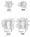
- Figure 1C is a view generally perpendicular to the Figure 1B view. As shown, the "flat" surface 54 is not truly flat, but actually has a slight barrel shape. With this prior art, there is sometimes a problem in that the slider block 38 has migrated vertically upwardly, and contacted the rear surface 60 of the base 27. This is undesirable.
- the driveshaft 34 is provided with an eccentric pin 136 that is received within a slider block 138.
- the slider block 138 is provided with a notch 142 at a vertically uppermost surface.
- the eccentric pin 36 is provided with a stop 140 at its vertically uppermost surface.
- the outer dimension of the eccentric pin at the stop 140 is shown at B. This dimension is less than the dimension of the bore within the slider block 138 shown at A. In this manner, the slider block can be simply dropped onto the eccentric pin.
- the stop will move over and be above the notch 142.
- the notch 142 extends for a greater length than does stop 140. This is to remove any alignment problems as the flat surfaces come into engagement.
- the present invention provides a simple and effective method of preventing a slider block from contacting the rear of a base of an orbiting scroll. While a preferred embodiment of this invention has been disclosed, a worker of ordinary skill in the art would recognize that certain modifications would come within the scope of this invention. For that reason, the following claims should be studies to determine the true scope and content of this invention.
Landscapes
- Engineering & Computer Science (AREA)
- Mechanical Engineering (AREA)
- General Engineering & Computer Science (AREA)
- Rotary Pumps (AREA)
Priority Applications (1)
| Application Number | Priority Date | Filing Date | Title |
|---|---|---|---|
| EP20070251632 EP1983196B1 (de) | 2007-04-18 | 2007-04-18 | Spiralverdichter mit Stoppstruktur zur Verhinderung von Bewegungen der Wellenbuchse |
Applications Claiming Priority (1)
| Application Number | Priority Date | Filing Date | Title |
|---|---|---|---|
| EP20070251632 EP1983196B1 (de) | 2007-04-18 | 2007-04-18 | Spiralverdichter mit Stoppstruktur zur Verhinderung von Bewegungen der Wellenbuchse |
Publications (2)
| Publication Number | Publication Date |
|---|---|
| EP1983196A1 true EP1983196A1 (de) | 2008-10-22 |
| EP1983196B1 EP1983196B1 (de) | 2011-07-20 |
Family
ID=38514091
Family Applications (1)
| Application Number | Title | Priority Date | Filing Date |
|---|---|---|---|
| EP20070251632 Not-in-force EP1983196B1 (de) | 2007-04-18 | 2007-04-18 | Spiralverdichter mit Stoppstruktur zur Verhinderung von Bewegungen der Wellenbuchse |
Country Status (1)
| Country | Link |
|---|---|
| EP (1) | EP1983196B1 (de) |
Cited By (2)
| Publication number | Priority date | Publication date | Assignee | Title |
|---|---|---|---|---|
| GB2452598A (en) * | 2007-09-05 | 2009-03-11 | Scroll Tech | Inclined flat drive surface in orbiting scroll slider block. |
| WO2013142696A1 (en) | 2012-03-23 | 2013-09-26 | Bitzer Kühlmaschinenbau Gmbh | Scroll compressor with slider block |
Citations (4)
| Publication number | Priority date | Publication date | Assignee | Title |
|---|---|---|---|---|
| US5439360A (en) * | 1991-07-22 | 1995-08-08 | Carrier Corporation | Self-adjusting crankshaft drive |
| JPH09329091A (ja) * | 1996-06-13 | 1997-12-22 | Daikin Ind Ltd | スクロール型流体装置 |
| US6053714A (en) * | 1997-12-12 | 2000-04-25 | Scroll Technologies, Inc. | Scroll compressor with slider block |
| EP1544469A1 (de) * | 2003-12-16 | 2005-06-22 | LG Electronics Inc. | Exzenterkupplungsvorrichtung eines Spiralverdichters mit radialer Nachgiebigkeit |
-
2007
- 2007-04-18 EP EP20070251632 patent/EP1983196B1/de not_active Not-in-force
Patent Citations (4)
| Publication number | Priority date | Publication date | Assignee | Title |
|---|---|---|---|---|
| US5439360A (en) * | 1991-07-22 | 1995-08-08 | Carrier Corporation | Self-adjusting crankshaft drive |
| JPH09329091A (ja) * | 1996-06-13 | 1997-12-22 | Daikin Ind Ltd | スクロール型流体装置 |
| US6053714A (en) * | 1997-12-12 | 2000-04-25 | Scroll Technologies, Inc. | Scroll compressor with slider block |
| EP1544469A1 (de) * | 2003-12-16 | 2005-06-22 | LG Electronics Inc. | Exzenterkupplungsvorrichtung eines Spiralverdichters mit radialer Nachgiebigkeit |
Cited By (5)
| Publication number | Priority date | Publication date | Assignee | Title |
|---|---|---|---|---|
| GB2452598A (en) * | 2007-09-05 | 2009-03-11 | Scroll Tech | Inclined flat drive surface in orbiting scroll slider block. |
| GB2452598B (en) * | 2007-09-05 | 2012-01-18 | Scroll Tech | Scroll compressor with tapered slider block |
| WO2013142696A1 (en) | 2012-03-23 | 2013-09-26 | Bitzer Kühlmaschinenbau Gmbh | Scroll compressor with slider block |
| EP2864635A4 (de) * | 2012-03-23 | 2016-04-13 | Bitzer Kuehlmaschinenbau Gmbh | Spiralverdichter mit schiebeblock |
| US9920762B2 (en) | 2012-03-23 | 2018-03-20 | Bitzer Kuehlmaschinenbau Gmbh | Scroll compressor with tilting slider block |
Also Published As
| Publication number | Publication date |
|---|---|
| EP1983196B1 (de) | 2011-07-20 |
Similar Documents
| Publication | Publication Date | Title |
|---|---|---|
| US9850904B2 (en) | Scroll compressor | |
| US5378129A (en) | Elastic unloader for scroll machines | |
| EP1181454B1 (de) | Vorrichtung zur verhinderung einer vakuumverdichtung in einem rollenverdichter | |
| EP2623789B1 (de) | Schraubenverdichter | |
| EP1205665B1 (de) | Spiralverdichter | |
| WO1993013316A1 (fr) | Compresseur a vis | |
| EP2236834A1 (de) | Einzelschraubenverdichter | |
| US6585502B2 (en) | Scroll compressor with slider block having circular portions in an inner bore | |
| EP1983196A1 (de) | Spiralverdichter mit Stoppstruktur zur Verhinderung von Bewegungen der Wellenbuchse | |
| CN1070266C (zh) | 涡旋流体机械 | |
| US7273363B1 (en) | Scroll compressor with slider block having recess | |
| US7284972B2 (en) | Scroll compressor with stop structure to prevent slider block movement | |
| US7273362B2 (en) | Scroll compressor with an eccentric pin having a higher contact point | |
| US7476092B1 (en) | Scroll compressor with tapered slider block | |
| US7481632B1 (en) | Scroll compressor with an oil passage plug to limit oil flow | |
| JP2008267282A (ja) | スライダブロックの移動を防止するための止め具構造を有するスクロール圧縮機 | |
| US6471499B1 (en) | Scroll compressor with lubrication directed to drive flat surfaces | |
| CN101889143A (zh) | 单螺杆压缩机 | |
| US6203300B1 (en) | Scroll compressor with structure for preventing reverse rotation | |
| KR20080093517A (ko) | 슬라이더 블록의 운동을 방지하기 위한 스톱 구조물을포함하는 스크롤 압축기 | |
| US20120244026A1 (en) | Counterweight incorporated into slider block for scroll compressor | |
| US6634875B2 (en) | Scroll compressor having an Oldham's ring containing silicon particles | |
| JP2005127173A (ja) | スクロ−ル圧縮機 | |
| US6361297B1 (en) | Scroll compressor with pivoting slider block and improved bore configuration | |
| EP4098877B1 (de) | Spiralverdichter |
Legal Events
| Date | Code | Title | Description |
|---|---|---|---|
| PUAI | Public reference made under article 153(3) epc to a published international application that has entered the european phase |
Free format text: ORIGINAL CODE: 0009012 |
|
| AK | Designated contracting states |
Kind code of ref document: A1 Designated state(s): AT BE BG CH CY CZ DE DK EE ES FI FR GB GR HU IE IS IT LI LT LU LV MC MT NL PL PT RO SE SI SK TR |
|
| AX | Request for extension of the european patent |
Extension state: AL BA HR MK RS |
|
| 17P | Request for examination filed |
Effective date: 20090205 |
|
| 17Q | First examination report despatched |
Effective date: 20090304 |
|
| AKX | Designation fees paid |
Designated state(s): BE DE ES FR GB IT |
|
| GRAP | Despatch of communication of intention to grant a patent |
Free format text: ORIGINAL CODE: EPIDOSNIGR1 |
|
| RIN1 | Information on inventor provided before grant (corrected) |
Inventor name: SUN, ZILI |
|
| GRAS | Grant fee paid |
Free format text: ORIGINAL CODE: EPIDOSNIGR3 |
|
| GRAA | (expected) grant |
Free format text: ORIGINAL CODE: 0009210 |
|
| AK | Designated contracting states |
Kind code of ref document: B1 Designated state(s): BE DE ES FR GB IT |
|
| REG | Reference to a national code |
Ref country code: GB Ref legal event code: FG4D |
|
| REG | Reference to a national code |
Ref country code: DE Ref legal event code: R096 Ref document number: 602007015896 Country of ref document: DE Effective date: 20110915 |
|
| PG25 | Lapsed in a contracting state [announced via postgrant information from national office to epo] |
Ref country code: BE Free format text: LAPSE BECAUSE OF FAILURE TO SUBMIT A TRANSLATION OF THE DESCRIPTION OR TO PAY THE FEE WITHIN THE PRESCRIBED TIME-LIMIT Effective date: 20110720 |
|
| PLBE | No opposition filed within time limit |
Free format text: ORIGINAL CODE: 0009261 |
|
| STAA | Information on the status of an ep patent application or granted ep patent |
Free format text: STATUS: NO OPPOSITION FILED WITHIN TIME LIMIT |
|
| PG25 | Lapsed in a contracting state [announced via postgrant information from national office to epo] |
Ref country code: IT Free format text: LAPSE BECAUSE OF FAILURE TO SUBMIT A TRANSLATION OF THE DESCRIPTION OR TO PAY THE FEE WITHIN THE PRESCRIBED TIME-LIMIT Effective date: 20110720 |
|
| 26N | No opposition filed |
Effective date: 20120423 |
|
| REG | Reference to a national code |
Ref country code: DE Ref legal event code: R097 Ref document number: 602007015896 Country of ref document: DE Effective date: 20120423 |
|
| GBPC | Gb: european patent ceased through non-payment of renewal fee |
Effective date: 20120418 |
|
| REG | Reference to a national code |
Ref country code: FR Ref legal event code: ST Effective date: 20121228 |
|
| PG25 | Lapsed in a contracting state [announced via postgrant information from national office to epo] |
Ref country code: GB Free format text: LAPSE BECAUSE OF NON-PAYMENT OF DUE FEES Effective date: 20120418 |
|
| PG25 | Lapsed in a contracting state [announced via postgrant information from national office to epo] |
Ref country code: FR Free format text: LAPSE BECAUSE OF NON-PAYMENT OF DUE FEES Effective date: 20120430 |
|
| PG25 | Lapsed in a contracting state [announced via postgrant information from national office to epo] |
Ref country code: ES Free format text: LAPSE BECAUSE OF FAILURE TO SUBMIT A TRANSLATION OF THE DESCRIPTION OR TO PAY THE FEE WITHIN THE PRESCRIBED TIME-LIMIT Effective date: 20111031 |
|
| PGFP | Annual fee paid to national office [announced via postgrant information from national office to epo] |
Ref country code: DE Payment date: 20150414 Year of fee payment: 9 |
|
| REG | Reference to a national code |
Ref country code: DE Ref legal event code: R119 Ref document number: 602007015896 Country of ref document: DE |
|
| PG25 | Lapsed in a contracting state [announced via postgrant information from national office to epo] |
Ref country code: DE Free format text: LAPSE BECAUSE OF NON-PAYMENT OF DUE FEES Effective date: 20161101 |