EP1983234A1 - Structure d'etancheite de recipient sous pression - Google Patents
Structure d'etancheite de recipient sous pression Download PDFInfo
- Publication number
- EP1983234A1 EP1983234A1 EP06712720A EP06712720A EP1983234A1 EP 1983234 A1 EP1983234 A1 EP 1983234A1 EP 06712720 A EP06712720 A EP 06712720A EP 06712720 A EP06712720 A EP 06712720A EP 1983234 A1 EP1983234 A1 EP 1983234A1
- Authority
- EP
- European Patent Office
- Prior art keywords
- lid
- pressure vessel
- opening end
- seal structure
- vessel
- Prior art date
- Legal status (The legal status is an assumption and is not a legal conclusion. Google has not performed a legal analysis and makes no representation as to the accuracy of the status listed.)
- Withdrawn
Links
- 229910052751 metal Inorganic materials 0.000 claims abstract description 17
- 239000002184 metal Substances 0.000 claims abstract description 17
- 239000011261 inert gas Substances 0.000 claims abstract description 10
- 210000004907 gland Anatomy 0.000 claims description 5
- 238000012856 packing Methods 0.000 claims description 5
- 238000007789 sealing Methods 0.000 abstract description 7
- 239000011347 resin Substances 0.000 description 9
- 229920005989 resin Polymers 0.000 description 9
- 239000012080 ambient air Substances 0.000 description 8
- 239000002994 raw material Substances 0.000 description 8
- 239000003570 air Substances 0.000 description 7
- 230000002093 peripheral effect Effects 0.000 description 7
- 230000008602 contraction Effects 0.000 description 5
- 239000007788 liquid Substances 0.000 description 5
- 239000007789 gas Substances 0.000 description 3
- 238000010438 heat treatment Methods 0.000 description 3
- 238000004519 manufacturing process Methods 0.000 description 3
- 239000000126 substance Substances 0.000 description 3
- 230000008646 thermal stress Effects 0.000 description 3
- 238000003466 welding Methods 0.000 description 3
- IJGRMHOSHXDMSA-UHFFFAOYSA-N Atomic nitrogen Chemical compound N#N IJGRMHOSHXDMSA-UHFFFAOYSA-N 0.000 description 2
- PXHVJJICTQNCMI-UHFFFAOYSA-N Nickel Chemical compound [Ni] PXHVJJICTQNCMI-UHFFFAOYSA-N 0.000 description 2
- 238000012423 maintenance Methods 0.000 description 2
- 230000000379 polymerizing effect Effects 0.000 description 2
- 238000005406 washing Methods 0.000 description 2
- RYGMFSIKBFXOCR-UHFFFAOYSA-N Copper Chemical compound [Cu] RYGMFSIKBFXOCR-UHFFFAOYSA-N 0.000 description 1
- 229910001209 Low-carbon steel Inorganic materials 0.000 description 1
- 239000000654 additive Substances 0.000 description 1
- 230000004075 alteration Effects 0.000 description 1
- 229910052782 aluminium Inorganic materials 0.000 description 1
- XAGFODPZIPBFFR-UHFFFAOYSA-N aluminium Chemical compound [Al] XAGFODPZIPBFFR-UHFFFAOYSA-N 0.000 description 1
- 239000010425 asbestos Substances 0.000 description 1
- 239000011248 coating agent Substances 0.000 description 1
- 238000000576 coating method Methods 0.000 description 1
- 239000000470 constituent Substances 0.000 description 1
- 229910052802 copper Inorganic materials 0.000 description 1
- 239000010949 copper Substances 0.000 description 1
- 238000010586 diagram Methods 0.000 description 1
- 239000000835 fiber Substances 0.000 description 1
- 239000012784 inorganic fiber Substances 0.000 description 1
- 230000001788 irregular Effects 0.000 description 1
- 239000000314 lubricant Substances 0.000 description 1
- 239000000463 material Substances 0.000 description 1
- 229910052759 nickel Inorganic materials 0.000 description 1
- 229910052757 nitrogen Inorganic materials 0.000 description 1
- 229920000642 polymer Polymers 0.000 description 1
- 229910052895 riebeckite Inorganic materials 0.000 description 1
- 239000010409 thin film Substances 0.000 description 1
Images


Classifications
-
- F—MECHANICAL ENGINEERING; LIGHTING; HEATING; WEAPONS; BLASTING
- F16—ENGINEERING ELEMENTS AND UNITS; GENERAL MEASURES FOR PRODUCING AND MAINTAINING EFFECTIVE FUNCTIONING OF MACHINES OR INSTALLATIONS; THERMAL INSULATION IN GENERAL
- F16J—PISTONS; CYLINDERS; SEALINGS
- F16J13/00—Covers or similar closure members for pressure vessels in general
- F16J13/02—Detachable closure members; Means for tightening closures
-
- F—MECHANICAL ENGINEERING; LIGHTING; HEATING; WEAPONS; BLASTING
- F16—ENGINEERING ELEMENTS AND UNITS; GENERAL MEASURES FOR PRODUCING AND MAINTAINING EFFECTIVE FUNCTIONING OF MACHINES OR INSTALLATIONS; THERMAL INSULATION IN GENERAL
- F16J—PISTONS; CYLINDERS; SEALINGS
- F16J15/00—Sealings
- F16J15/002—Sealings comprising at least two sealings in succession
- F16J15/004—Sealings comprising at least two sealings in succession forming of recuperation chamber for the leaking fluid
-
- F—MECHANICAL ENGINEERING; LIGHTING; HEATING; WEAPONS; BLASTING
- F16—ENGINEERING ELEMENTS AND UNITS; GENERAL MEASURES FOR PRODUCING AND MAINTAINING EFFECTIVE FUNCTIONING OF MACHINES OR INSTALLATIONS; THERMAL INSULATION IN GENERAL
- F16J—PISTONS; CYLINDERS; SEALINGS
- F16J15/00—Sealings
- F16J15/02—Sealings between relatively-stationary surfaces
- F16J15/14—Sealings between relatively-stationary surfaces by means of granular or plastic material, or fluid
Definitions
- the present invention relates to a seal structure of a pressure vessel which includes a bottomed tubular vessel body provided with an opening end, and a lid which covers the opening end, and specifically, to a seal structure of the pressure vessel which is heated to a high temperature of, for example, about 250 to 400°C.
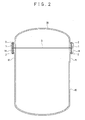
- a pressure vessel as shown in FIG. 2 or 3 is used as an apparatus for polymerizing resin.
- This pressure vessel includes a bottomed tubular vessel body 10 in a vertical posture provided with an opening end 11, and a lid 20 which covers the opening end 11.
- the opening end 11 of the vessel body 10 is provided with an outward flange 14, an outer peripheral portion of the lid 20 is joined to the outward flange 14, and both the opening end 11 and the lid 20 are fixed together by bolts 1 and nuts 2.
- FIG. 4 there are a semi-spherical or semi-elliptical lid as shown in FIG. 2 , and a thick plate-shaped lid as shown in FIG. 3 .
- weld-ring gaskets 5 for increasing the sealing performance in the pressure vessel are used between the lid 20 and the opening end 11 of the vessel body 10.
- the weld-ring gaskets 5 are thin metal rings which are used in a state where two gaskets overlap each other, outer peripheral ends 5a, 5a on the side of joining faces of the gaskets protrude further away from portions on the side of non-joining faces of the gaskets, and sealing is completely performed by welding the outer peripheral ends 5a and 5a.
- FIG. 4 is a schematic diagram in which the lid 20 shown in FIG. 2 is enlarged, the same weld-ring gaskets 5 are used even in the lid 20 shown in FIG. 3 .
- jackets through which heating medium oil with a high temperature of, for example, about 250 to 400°C flows are additionally provided at an upper face of the lid 20 and at an outer peripheral surface of the vessel body 10. Moreover, the inside of the pressure vessel is kept in a high vacuum state, and a raw material is caused to flow in through a portion of the lid 20. Resin is polymerized within the vessel body 10 from the raw material, and this resin is discharged through a lower end of the vessel body 10.
- the pressure vessel expands as being heated to a high temperature of, for example, about 250 to 400°C, and the pressure vessel contracts when the heating ends. Accordingly, the weld-ring gaskets 5 used between the vessel body 10 and the lid 20 expand and contract thermally.
- the upper and lower weld-ring gaskets 5 differ in thermal contraction, and consequently thermal stress is generated. Then, welded portions of the weld-ring gaskets 5 may be cracked due to the thermal stress, and a gap may be created. As ambient air flows into the pressure vessel through this gap, resin polymerized within the vessel body 10 will increases irregular products which do not have predetermined quality, that is, deteriorates the yield.
- an object of the invention is to provide a seal structure of a pressure vessel adapted to surely maintain sealing performance even if thermal expansion and contraction take place.
- a seal structure of a pressure vessel that includes a bottomed tubular vessel body provided with an opening end and a lid closing the opening end.
- Annular grooves and ridges fitted to each other are formed on both of the inner and outer sides at the joining faces of the opening end of the vessel body and the lid, an annular vent hole is formed between the inner ridge and the outer ridge, an air supply hole for supplying an inert gas to the vent hole is formed in the lid or the vessel body, and the joining faces inside the inner ridge and the inner groove are in metal-to-metal contact, and gaskets are held between the ridges and the grooves.
- annular grooves and ridges fitted to each other are formed on both of the inner and outer sides at the joining faces of the opening end of the vessel body and the lid, an annular vent hole filled with an inert gas is formed between the inner ridge and the outer ridge, and gaskets are held between the ridges and the grooves.
- the joining faces inside the inner ridge and groove are in metal-to-metal contact.
- the lid is formed by integrating together a lid body and a frame body joined to the opening end of the vessel body, and the frame body is formed with both the ridges.
- the ridges are formed in the frame body integrated with the lid body. Thereby, the ridges can be formed easily.
- the inside of the frame body joined to the lid is formed with a concave curved surface.
- a concave curved surface is formed in the frame body.
- the gasket held between the inner ridge and groove is a metal jacket gasket
- the gasket held between the outer ridge and groove is gland packing.
- a metal jacket gasket having excellent thermal resistance is used as the gasket held between the inner ridge and groove.
- gland packing to be suitably used in a portion to which a tensional force is applied is used as the gasket held between the outer ridge and groove.
- annular grooves and ridges fitted to each other are formed on both of the inner and outer sides at the joining faces of the opening end of the vessel body and the lid, an annular vent hole filled with an inert gas is formed between the inner ridge and the outer ridge, and gaskets are held between the ridges and the grooves.
- this pressure vessel also includes a bottomed vessel body 10 in a vertical posture provided with an opening end 11, a lid 20 which covers the opening end 11, and an outward flange 14 provided at the opening end 11 of the vessel body 10, in which an outer peripheral portion of the lid 20 are fastened together by bolts 1 and nuts 2.
- the vessel body 10 is provided with a seal structure as shown in FIG. 1 .
- This seal structure is formed at each of joining faces of the opening end 11 of the vessel body 10 and the lid 20, and is configured about double annular grooves 11a and 11b and ridges 21a and 21b which are fitted to each other.
- the annular grooves 11a and 11b are formed at the joining face of the opening end 11 of the vessel body 10, and the annular ridges 21a and 21b are formed at the frame body 21 provided in the lid body 20a.
- the frame body 21 has the same internal diameter as the internal diameter of the opening end 11 of the vessel body 10, and is integrated with the lid body 20a by welding, etc.
- the ridges 21a, 21b are formed at the frame body 21 and are integrated with the lid body 20a, the ridges 21a and 21b can be easily formed at the lid body 20a.
- an annular vent hole 30 is provided between the inner ridge 21a and the outer ridge 21b.
- the inside of the vent hole 30 is adapted to be filled with inert gas, such as nitrogen, to be supplied through an air supply hole 31.
- the air supply hole 31 is exposed to the surface of the lid 20, and is connected to a pipe (not shown).
- the air supply hole 31 is formed at the opening end 11 of the vessel body 10 instead of the lid 20.
- both the joining faces of the frame body 21 of the lid 20 and the opening end 11 of the vessel body 10 are joined together inside the inner ridge 21a and groove 11a by metal-to-metal contact. As both the joining faces are brought into tight contact with each other by metal-to-metal contact, a raw material which has flowed into the pressure vessel can be prevented from stagnating between the frame body 21 of the lid 20 and the opening end 11 of the vessel body 10.
- gaskets 51a and 51b are held between the ridges 21a and 21b and the grooves 11a and 11b. Even if the fastening margin of the gaskets is insufficient due to manufacturing errors, the gaskets 51a and 51b prevent ambient air from entering the pressure vessel. Further, the grooves 11a and 11b are formed at the joining faces of the opening end 11 of the vessel body 10, and the gaskets 51a and 51b are fitted into the grooves 11a and 11b so as to be dropped thereinto. Thereby, the gaskets 51a and 51b are not displaced.
- a metal jacket gasket is used so that metal-to-metal contact can be maintained.
- the metal jacket gasket is one obtained by coating a core, such as a non-asbestos cushioning material, with a metal thin film, such as mild steel, copper, nickel, or aluminum, and has the feature that thermal resistance is excellent.
- gland packing is used so that the outside where the bolts 1 and the nuts 2 are fastened together can be sealed suitably.
- the gland packing is one molded from various kinds of lubricant and caking additives, using inorganic fibers or organic fibers as a main constituent, and is used while a tensional force is given thereto.
- an inner periphery of the frame body 21 is formed with a concave curved surface so that a corner is not provided at a boundary portion between the frame body and the lid body 20a.
- This concave curved surface prevents the liquid raw material caused to flow into the pressure vessel from stagnating at an inner corner of the lid 20.
- the lid 20 closes the opening end 11 of the vessel body 10 in the pressure vessel provided with such a seal structure
- the ridges 21a and 21b are fitted into the grooves 11a and 11b with the gaskets 51a and 51b held therebetween, and the bolts 1 and the nuts 2 are fastened together with the inner joining faces being in metal-to-metal contact.
- inert gas is supplied into the vent hole 30 through the air supply hole 31, the liquid raw material is caused to flow into the vessel body 10 through a portion of the lid 20.
- the bolts 1 and the nuts 2 which fasten the vessel body 10 and the lid 20 together are unfastened, and the lid 20 is removed.
- the gaskets 51a and 51b can be removed from the opening end 11 of the vessel body 10.
- this pressure vessel can also be used not as an apparatus for manufacturing polymers, but as an apparatus which fills liquid gas or pressurized substance.
- the pressure vessel can be similarly implemented not in a vertical posture but in a horizontal posture and in an inclined posture.
- the ridge 21a and 21b and the groove 11a and 11b may be provided not as double structure, but as triple or more structure.
- the seal structure of the pressure vessel of the present invention can be effectively utilized for a pressure vessel which is used as an apparatus for polymerizing resin at a high temperature of 250 to 400°C, or an apparatus for filling liquid gas or pressurized substance.
Landscapes
- Engineering & Computer Science (AREA)
- General Engineering & Computer Science (AREA)
- Mechanical Engineering (AREA)
- Pressure Vessels And Lids Thereof (AREA)
- Gasket Seals (AREA)
Applications Claiming Priority (1)
| Application Number | Priority Date | Filing Date | Title |
|---|---|---|---|
| PCT/JP2006/301577 WO2007088593A1 (fr) | 2006-01-31 | 2006-01-31 | Structure d'étanchéité de récipient sous pression |
Publications (1)
| Publication Number | Publication Date |
|---|---|
| EP1983234A1 true EP1983234A1 (fr) | 2008-10-22 |
Family
ID=38327181
Family Applications (1)
| Application Number | Title | Priority Date | Filing Date |
|---|---|---|---|
| EP06712720A Withdrawn EP1983234A1 (fr) | 2006-01-31 | 2006-01-31 | Structure d'etancheite de recipient sous pression |
Country Status (8)
| Country | Link |
|---|---|
| US (1) | US20100181324A1 (fr) |
| EP (1) | EP1983234A1 (fr) |
| JP (1) | JP4966870B2 (fr) |
| CN (1) | CN101360935A (fr) |
| BR (1) | BRPI0621196A2 (fr) |
| RU (1) | RU2383803C1 (fr) |
| TW (1) | TW200730747A (fr) |
| WO (1) | WO2007088593A1 (fr) |
Cited By (2)
| Publication number | Priority date | Publication date | Assignee | Title |
|---|---|---|---|---|
| EP2423540A1 (fr) * | 2010-08-25 | 2012-02-29 | Aisin Seiki Kabushiki Kaisha | Structure de joint |
| US20120095208A1 (en) * | 2009-06-26 | 2012-04-19 | Amorepacific Corporation | Positive and negative extraction device and extraction method |
Families Citing this family (15)
| Publication number | Priority date | Publication date | Assignee | Title |
|---|---|---|---|---|
| DE112008004249T5 (de) * | 2008-11-18 | 2012-02-23 | Toyota Jidosha Kabushiki Kaisha | Hochdrucktank |
| EP2992279B1 (fr) | 2013-04-29 | 2020-12-30 | Carrier Corporation | Joint a faibles fuites pour système à basse pression |
| US9498808B2 (en) * | 2013-07-26 | 2016-11-22 | Ube Machinery Corporation, Ltd. | Container degassing device for extrusion press |
| JP6343454B2 (ja) * | 2014-01-30 | 2018-06-13 | 千代田化工建設株式会社 | シール構造およびシール方法 |
| CN104964032A (zh) * | 2015-06-04 | 2015-10-07 | 江苏进源压力容器有限公司 | 一种压力容器密封盖 |
| CN105156338A (zh) * | 2015-09-25 | 2015-12-16 | 珠海格力电器股份有限公司 | 自吸水泵及设置有该自吸水泵的饮水机和加湿器 |
| RU184266U1 (ru) * | 2016-06-28 | 2018-10-19 | Федеральное государственное бюджетное образовательное учреждение высшего образования Балтийский государственный технический университет "ВОЕНМЕХ" им. Д.Ф. Устинова (БГТУ "ВОЕНМЕХ") | Узел уплотнения неподвижных соединений |
| CN106512032B (zh) * | 2016-12-09 | 2022-06-28 | 昆山新莱洁净应用材料股份有限公司 | 一种配备双重联锁功能的全自动蒸汽灭菌器 |
| WO2018146817A1 (fr) * | 2017-02-13 | 2018-08-16 | 堺ディスプレイプロダクト株式会社 | Dispositif à vide |
| JP6968286B2 (ja) * | 2018-11-12 | 2021-11-17 | Jfeスチール株式会社 | 高圧水素容器 |
| CN112431975B (zh) * | 2020-11-04 | 2022-07-19 | 李岐 | 一种密封结构及密封方法 |
| CN115234834A (zh) * | 2021-04-22 | 2022-10-25 | 辛集市皓瑞封头制造有限公司 | 一种便于修复的压力容器 |
| WO2022256517A1 (fr) * | 2021-06-02 | 2022-12-08 | Feldmeier Equipment, Inc. | Accessoire hygiénique pour équipement de traitement sanitaire |
| CN116927321B (zh) * | 2023-07-24 | 2025-11-28 | 广东华茂水电生态集团有限公司 | 一种水利工程排涝站用压力水箱 |
| CN119408868A (zh) * | 2024-11-07 | 2025-02-11 | 安徽广信农化股份有限公司 | 一种磺酰基异氰酸酯的机械密封设备 |
Family Cites Families (80)
| Publication number | Priority date | Publication date | Assignee | Title |
|---|---|---|---|---|
| US1715854A (en) * | 1923-03-06 | 1929-06-04 | Standard Dev Co | Fluid-tight joint |
| US1835921A (en) * | 1928-06-23 | 1931-12-08 | Commercial Solvents Corp | High pressure joint |
| US2016226A (en) * | 1932-01-27 | 1935-10-01 | Harrisburg Steel Corp | Liquefier tank and method of sealing same |
| US1904250A (en) * | 1932-04-27 | 1933-04-18 | Pure Carbonic Company Of Ameri | Automatic pressure sealing means |
| US2264760A (en) * | 1939-08-31 | 1941-12-02 | Elmer M Kling | Fill pipe box |
| US2376593A (en) * | 1943-10-09 | 1945-05-22 | Bendix Aviat Corp | Design of bezel sealing for pressureproof cases |
| US2611506A (en) * | 1949-06-28 | 1952-09-23 | Foote Mineral Co | Sealing structure of the gasket type |
| US2744655A (en) * | 1953-09-22 | 1956-05-08 | Vnuk Josef | Lined container and closure therefor |
| US2903152A (en) * | 1954-09-24 | 1959-09-08 | Chemical Construction Corp | Closure and seal for pressure vessels |
| US2828789A (en) * | 1955-08-12 | 1958-04-01 | Wilbro Corp | Containers |
| US3230290A (en) * | 1961-02-23 | 1966-01-18 | Shell Oil Co | Composite gasket and method of applying same |
| US3091265A (en) * | 1961-06-22 | 1963-05-28 | United States Steel Corp | Vacuum-sealed flexible port union |
| US3208758A (en) * | 1961-10-11 | 1965-09-28 | Varian Associates | Metal vacuum joint |
| US3181873A (en) * | 1962-01-25 | 1965-05-04 | Nat Res Corp | High torque, high speed rotary feedthrough seal for ultrahigh vacuum chambers |
| US3144035A (en) * | 1963-02-01 | 1964-08-11 | Nat Res Corp | High vacuum system |
| US3270910A (en) * | 1963-06-28 | 1966-09-06 | Chicago Bridge & Iron Co | Joint structure |
| US3328039A (en) * | 1965-02-08 | 1967-06-27 | Ite Circuit Breaker Ltd | Leak-proof seal |
| GB1219905A (en) * | 1967-06-27 | 1971-01-20 | Struthers Scientific Int Corp | End closure for pressure vessel |
| CH478362A (de) * | 1967-07-27 | 1969-09-15 | Sulzer Ag | Verschluss eines Druckgefässes mit in einer gewölbten Wand des Gefässes angeordnetem Verschlussdeckel |
| US3847420A (en) * | 1970-02-10 | 1974-11-12 | Weston Instruments Inc | Industrial technique |
| US3655090A (en) * | 1970-06-25 | 1972-04-11 | Chicago Bridge & Iron Co | Vessel and closure with interlocking shear ring joint |
| US3802220A (en) * | 1973-06-20 | 1974-04-09 | Kool Pak Corp | Cooling cushion |
| US3910448A (en) * | 1974-05-31 | 1975-10-07 | Raychem Sa Nv | Heat recoverable closure assembly |
| US3895735A (en) * | 1974-07-08 | 1975-07-22 | Hahn & Clay | Vessel with pre-compressed seal |
| US4054224A (en) * | 1974-07-08 | 1977-10-18 | Hahn & Clay | Vessel assembly |
| JPS5127917U (fr) * | 1974-08-21 | 1976-02-28 | ||
| US4009798A (en) * | 1975-05-07 | 1977-03-01 | Hahn & Clay | Vessel connector |
| US4014456A (en) * | 1975-10-31 | 1977-03-29 | Mary Louise Echtle | Insulated sandwich and salad keeper |
| US4145895A (en) * | 1977-01-06 | 1979-03-27 | Hjertstrand Ake W | Apparatus for storing goods at stable temperatures in a heat-insulated container |
| DE2837541A1 (de) * | 1978-08-10 | 1980-02-14 | Bbc Brown Boveri & Cie | Verbindung von bauelementen |
| US4303251A (en) * | 1978-12-04 | 1981-12-01 | Varian Associates, Inc. | Flange sealing joint with removable metal gasket |
| US4299332A (en) * | 1979-02-22 | 1981-11-10 | Hahn & Clay | Pressure vessel seal |
| US4240561A (en) * | 1979-05-16 | 1980-12-23 | Chicago Bridge & Iron Company | Flanged connection for pressure vessel |
| US4298204A (en) * | 1980-01-21 | 1981-11-03 | Black & Decker Inc. | Seal |
| US4305593A (en) * | 1980-04-28 | 1981-12-15 | Chemetron Process Equipment, Inc. | Seal |
| US4398649A (en) * | 1981-10-29 | 1983-08-16 | Combustion Engineering, Inc. | Primary manway cover removal |
| US4402422A (en) * | 1981-11-10 | 1983-09-06 | Pittsburgh-Des Moines Corporation | Field adjustable seal |
| US4438866A (en) * | 1982-08-03 | 1984-03-27 | Westinghouse Electric Corp. | Prestressed dome closure flange |
| US4620061A (en) * | 1984-09-10 | 1986-10-28 | Appleton Electric Co. | Fully grounded, corrosion resistant electrical enclosure |
| US4589564A (en) * | 1985-04-04 | 1986-05-20 | United Technologies Corporation | Pressure vessel opening seal |
| US4842287A (en) * | 1987-10-22 | 1989-06-27 | Helix Technology Corporation | Helium pressure seal for a cryogenic refrigerator |
| US5031509A (en) * | 1988-03-25 | 1991-07-16 | Titan Tool, Inc. | Anti-leak seal for pump motor |
| JPH02190674A (ja) * | 1989-01-18 | 1990-07-26 | Nissen Corp | 圧力容器のシール構造 |
| US5050764A (en) * | 1990-03-08 | 1991-09-24 | Pacesetter Infusion, Ltd. | Lateral compression sealing system and method of making seal |
| US5111362A (en) * | 1990-09-18 | 1992-05-05 | Intel Corporation | Enclosure assembly with two identical covers having modifiable supports for asymmetrically housing a printed circuit board or the like |
| JPH0648054B2 (ja) * | 1990-11-19 | 1994-06-22 | 東洋酸素株式会社 | 極低温槽における気密シール方法 |
| JP3106172B2 (ja) * | 1991-02-26 | 2000-11-06 | 東京エレクトロン株式会社 | 熱処理装置の封止構造 |
| US5238137A (en) * | 1991-12-16 | 1993-08-24 | Church Of Spiritual Technology | Long-term storage container |
| US5280924A (en) * | 1992-02-28 | 1994-01-25 | Dresser-Rand Company | Automatic seal depressurization system |
| JP3121915B2 (ja) * | 1992-06-01 | 2001-01-09 | 東京エレクトロン株式会社 | 封止装置 |
| US5391887A (en) * | 1993-02-10 | 1995-02-21 | Trustees Of Princeton University | Method and apparatus for the management of hazardous waste material |
| DE69427645T2 (de) * | 1993-10-06 | 2002-05-08 | Unit Instruments, Inc. | Apparat zur handhabung von prozess fluiden |
| US5516122A (en) * | 1993-12-10 | 1996-05-14 | Caffee; Barry K. | Ultra high vacuum elastomer seal |
| US5481790A (en) * | 1994-07-01 | 1996-01-09 | Clarus Technologies Corp. | Method for allowing selective access to the interior of fluid containment structures |
| US5560511A (en) * | 1995-01-06 | 1996-10-01 | The United States Of America As Represented By The Secretary Of The Army | Hermetically sealable reusable container |
| JP3355081B2 (ja) * | 1995-02-16 | 2002-12-09 | 矢崎総業株式会社 | 防水ケース |
| US5687975A (en) * | 1996-08-21 | 1997-11-18 | Fel-Pro Incorporated | Sealing assembly employing oppositely directed wedges and complementary recesses |
| DE19634673C2 (de) * | 1996-08-28 | 1998-08-27 | Stahl R Schaltgeraete Gmbh | Kunststoffgehäuse in der Zündschutzart "Druckfeste Kapselung" |
| US5938209A (en) * | 1997-02-14 | 1999-08-17 | Alternative Fuel Systems, Inc. | Seal system for fluid pressure vessels |
| US6000422A (en) * | 1997-05-08 | 1999-12-14 | Shigemoto & Annette Ii, Inc. | Fluid device with double containment |
| US5887746A (en) * | 1997-11-24 | 1999-03-30 | Pilot Industries, Inc. | High vacuum housing with improved sealing means |
| US6435365B2 (en) * | 1999-06-08 | 2002-08-20 | Delphi Technologies, Inc. | Seal assembly for a fuel tank |
| US6361055B1 (en) * | 1999-08-23 | 2002-03-26 | Northrop Grumman Corporation | Cryogenic composite tank seals |
| US6361049B1 (en) * | 2000-02-15 | 2002-03-26 | Honeywell International Inc. | Recessed groove/seal surface for seal effectiveness |
| US6510959B1 (en) * | 2000-04-18 | 2003-01-28 | United States Filter Corporation | Center opening treatment tank for use with metal tank flanges |
| JP2001326475A (ja) * | 2000-05-15 | 2001-11-22 | Nec Corp | 通信機器の防水構造 |
| US6309257B1 (en) * | 2000-08-09 | 2001-10-30 | Shining Blick Enterprises Co., Ltd. | Sealed, water-proof housing for an electrical device |
| EP1215950B1 (fr) * | 2000-12-13 | 2009-02-25 | Siemens Aktiengesellschaft | Boîtier d'actionneur avec joint d'étanchéité |
| US6439137B1 (en) * | 2001-03-16 | 2002-08-27 | Texaco Inc. | Self-anchoring expansion gap assembly for a gasifier |
| US20020162846A1 (en) * | 2001-05-03 | 2002-11-07 | Laurier Mercier | Cover and container combination for seal tight engagement |
| US6492590B1 (en) * | 2001-07-13 | 2002-12-10 | Ching Chi Cheng | Liquid-proof enclosure of electrical device |
| KR100589450B1 (ko) * | 2003-01-24 | 2006-06-14 | 가부시키가이샤 도요다 지도숏키 | 고압탱크 |
| BR0300905B1 (pt) * | 2003-03-28 | 2011-06-28 | sistema de fechamento de filtro de sucção para compressor hermético. | |
| US6838617B2 (en) * | 2003-05-01 | 2005-01-04 | Ultratech International, Inc. | Macroencapsulation container having both releasable and permanent sealing means |
| US7186912B2 (en) * | 2003-09-26 | 2007-03-06 | Avanex Corporation | Hermetic lid seal by metal pressing for fiber optic module |
| JP2006009984A (ja) * | 2004-06-28 | 2006-01-12 | Showa Engineering Co Ltd | ガスシール構造 |
| US7213814B2 (en) * | 2004-07-28 | 2007-05-08 | Federal-Mogul Worldwide, Inc. | Seal assembly |
| CN101360936B (zh) * | 2006-01-31 | 2010-10-13 | 住友重机械过程机器株式会社 | 压力容器用波纹件 |
| JP5144908B2 (ja) * | 2006-03-06 | 2013-02-13 | 矢崎総業株式会社 | 防水ケース |
| UA30713U (uk) * | 2007-11-02 | 2008-03-11 | Открытое Акционерное Общество "Главный Специализированный Конструктроско-Технологический Институт" | Герметичний затвор посудини, що працює під тиском |
-
2006
- 2006-01-31 RU RU2008135311/06A patent/RU2383803C1/ru active
- 2006-01-31 EP EP06712720A patent/EP1983234A1/fr not_active Withdrawn
- 2006-01-31 CN CNA2006800510879A patent/CN101360935A/zh active Pending
- 2006-01-31 JP JP2007556733A patent/JP4966870B2/ja not_active Expired - Fee Related
- 2006-01-31 WO PCT/JP2006/301577 patent/WO2007088593A1/fr not_active Ceased
- 2006-01-31 US US12/162,908 patent/US20100181324A1/en not_active Abandoned
- 2006-01-31 BR BRPI0621196-8A patent/BRPI0621196A2/pt not_active IP Right Cessation
- 2006-02-03 TW TW095103867A patent/TW200730747A/zh unknown
Non-Patent Citations (1)
| Title |
|---|
| See references of WO2007088593A1 * |
Cited By (2)
| Publication number | Priority date | Publication date | Assignee | Title |
|---|---|---|---|---|
| US20120095208A1 (en) * | 2009-06-26 | 2012-04-19 | Amorepacific Corporation | Positive and negative extraction device and extraction method |
| EP2423540A1 (fr) * | 2010-08-25 | 2012-02-29 | Aisin Seiki Kabushiki Kaisha | Structure de joint |
Also Published As
| Publication number | Publication date |
|---|---|
| CN101360935A (zh) | 2009-02-04 |
| JP4966870B2 (ja) | 2012-07-04 |
| WO2007088593A1 (fr) | 2007-08-09 |
| JPWO2007088593A1 (ja) | 2009-06-25 |
| BRPI0621196A2 (pt) | 2011-12-06 |
| TW200730747A (en) | 2007-08-16 |
| US20100181324A1 (en) | 2010-07-22 |
| RU2383803C1 (ru) | 2010-03-10 |
Similar Documents
| Publication | Publication Date | Title |
|---|---|---|
| EP1983234A1 (fr) | Structure d'etancheite de recipient sous pression | |
| US7287663B2 (en) | Lined pressure vessel and connector therefor | |
| KR20170017769A (ko) | 고압 탱크, 고압 탱크의 제조 방법, 시일성의 검사 방법 | |
| US9103739B2 (en) | Seal for pressure transmitter for use in industrial process | |
| FR2538075A1 (fr) | Liaison etanche aux gaz et aux liquides entre une piece de matiere plastique et une piece metallique enrobee dans cette derniere par coulee sous pression d'une masse de matiere plastique plastifiee, et procede d'enrobage avec etancheite aux gaz et aux liquides d'une piece metallique dans une piece de matiere plastique | |
| US11187324B2 (en) | Gaskets with a non-compressible core and one or more compressible layers | |
| JP3978021B2 (ja) | シールリング並びに複合材タンク、及び配管等のフランジ継手のシール構造 | |
| US7686867B2 (en) | Degasifier | |
| JPH063331B2 (ja) | 密封容器 | |
| US7644961B2 (en) | Tube joint | |
| US12331760B2 (en) | Hydraulic accumulator | |
| US20170363485A1 (en) | Structure for controlling tension on a threaded header | |
| KR20080097194A (ko) | 압력용기의 실링 구조 | |
| EP1983233A1 (fr) | Soufflet pour recipient sous pression | |
| US8596644B2 (en) | Seal structure for engine | |
| JP4680933B2 (ja) | シェルアンドチューブ式熱交換器 | |
| JP2007127153A (ja) | 極低温用フランジ継手の漏洩防止装置 | |
| KR100958675B1 (ko) | 벨로우즈 시일을 이용한 압력용기 밀폐구조 | |
| JP6154427B2 (ja) | ガスケット及びガスケットの製造方法 | |
| CN218686417U (zh) | 钢衬四氟蒸馏釜体 | |
| KR102865017B1 (ko) | 표면 누설 비파괴 검사를 위한 진공챔버 시험장치 | |
| CN211852777U (zh) | 压力容器的封盖装置 | |
| CN100368713C (zh) | 双环密封垫片及其制造方法 | |
| US20210372524A1 (en) | Seal Between Mutually Fixed Surfaces | |
| KR20080097193A (ko) | 압력용기용 벨로즈 |
Legal Events
| Date | Code | Title | Description |
|---|---|---|---|
| PUAI | Public reference made under article 153(3) epc to a published international application that has entered the european phase |
Free format text: ORIGINAL CODE: 0009012 |
|
| 17P | Request for examination filed |
Effective date: 20080825 |
|
| AK | Designated contracting states |
Kind code of ref document: A1 Designated state(s): DE HU NL |
|
| RBV | Designated contracting states (corrected) |
Designated state(s): DE HU NL |
|
| STAA | Information on the status of an ep patent application or granted ep patent |
Free format text: STATUS: THE APPLICATION IS DEEMED TO BE WITHDRAWN |
|
| 18D | Application deemed to be withdrawn |
Effective date: 20110802 |