EP1983295A1 - Schutzvorrichtung für einen Schwingkreis zur Leistungsübertragung - Google Patents
Schutzvorrichtung für einen Schwingkreis zur Leistungsübertragung Download PDFInfo
- Publication number
- EP1983295A1 EP1983295A1 EP07290482A EP07290482A EP1983295A1 EP 1983295 A1 EP1983295 A1 EP 1983295A1 EP 07290482 A EP07290482 A EP 07290482A EP 07290482 A EP07290482 A EP 07290482A EP 1983295 A1 EP1983295 A1 EP 1983295A1
- Authority
- EP
- European Patent Office
- Prior art keywords
- current
- measuring
- power circuit
- breaking
- analyzing
- Prior art date
- Legal status (The legal status is an assumption and is not a legal conclusion. Google has not performed a legal analysis and makes no representation as to the accuracy of the status listed.)
- Granted
Links
- 230000001681 protective effect Effects 0.000 claims 4
- 238000005259 measurement Methods 0.000 description 7
- 239000004020 conductor Substances 0.000 description 5
- 230000010355 oscillation Effects 0.000 description 3
- 238000010586 diagram Methods 0.000 description 2
- 238000011144 upstream manufacturing Methods 0.000 description 2
- 239000003086 colorant Substances 0.000 description 1
- 238000005516 engineering process Methods 0.000 description 1
- 238000011156 evaluation Methods 0.000 description 1
- 238000009413 insulation Methods 0.000 description 1
- 238000005065 mining Methods 0.000 description 1
- 230000004048 modification Effects 0.000 description 1
- 238000012986 modification Methods 0.000 description 1
- 230000003068 static effect Effects 0.000 description 1
- 230000007704 transition Effects 0.000 description 1
Images

Classifications
-
- F—MECHANICAL ENGINEERING; LIGHTING; HEATING; WEAPONS; BLASTING
- F41—WEAPONS
- F41H—ARMOUR; ARMOURED TURRETS; ARMOURED OR ARMED VEHICLES; MEANS OF ATTACK OR DEFENCE, e.g. CAMOUFLAGE, IN GENERAL
- F41H11/00—Defence installations; Defence devices
- F41H11/12—Means for clearing land minefields; Systems specially adapted for detection of landmines
-
- F—MECHANICAL ENGINEERING; LIGHTING; HEATING; WEAPONS; BLASTING
- F41—WEAPONS
- F41H—ARMOUR; ARMOURED TURRETS; ARMOURED OR ARMED VEHICLES; MEANS OF ATTACK OR DEFENCE, e.g. CAMOUFLAGE, IN GENERAL
- F41H11/00—Defence installations; Defence devices
- F41H11/12—Means for clearing land minefields; Systems specially adapted for detection of landmines
- F41H11/13—Systems specially adapted for detection of landmines
- F41H11/136—Magnetic, electromagnetic, acoustic or radiation systems, e.g. ground penetrating radars or metal-detectors
-
- F—MECHANICAL ENGINEERING; LIGHTING; HEATING; WEAPONS; BLASTING
- F41—WEAPONS
- F41H—ARMOUR; ARMOURED TURRETS; ARMOURED OR ARMED VEHICLES; MEANS OF ATTACK OR DEFENCE, e.g. CAMOUFLAGE, IN GENERAL
- F41H11/00—Defence installations; Defence devices
- F41H11/12—Means for clearing land minefields; Systems specially adapted for detection of landmines
- F41H11/16—Self-propelled mine-clearing vehicles; Mine-clearing devices attachable to vehicles
-
- B—PERFORMING OPERATIONS; TRANSPORTING
- B63—SHIPS OR OTHER WATERBORNE VESSELS; RELATED EQUIPMENT
- B63G—OFFENSIVE OR DEFENSIVE ARRANGEMENTS ON VESSELS; MINE-LAYING; MINE-SWEEPING; SUBMARINES; AIRCRAFT CARRIERS
- B63G7/00—Mine-sweeping; Vessels characterised thereby
- B63G7/02—Mine-sweeping means, Means for destroying mines
- B63G7/06—Mine-sweeping means, Means for destroying mines of electromagnetic type
-
- H—ELECTRICITY
- H01—ELECTRIC ELEMENTS
- H01F—MAGNETS; INDUCTANCES; TRANSFORMERS; SELECTION OF MATERIALS FOR THEIR MAGNETIC PROPERTIES
- H01F7/00—Magnets
- H01F7/06—Electromagnets; Actuators including electromagnets
- H01F7/08—Electromagnets; Actuators including electromagnets with armatures
- H01F7/18—Circuit arrangements for obtaining desired operating characteristics, e.g. for slow operation, for sequential energisation of windings, for high-speed energisation of windings
- H01F7/1844—Monitoring or fail-safe circuits
Definitions
- the technical field of the invention is that of devices for protecting oscillating power circuits.
- circuits including oscillating may be degraded by the presence of a direct current.
- the coils used in the electromagnetic demining devices are sensitive to DC currents which may, after a certain time, deteriorate them, even if these currents have a level of intensity which is below a given threshold.
- the object of the invention is to propose a protection device making it possible to protect against the appearance of such continuous currents.
- the subject of the invention is a device for protecting an oscillating power circuit, and in particular a demining coil, a device comprising a breaking means interposed between an AC supply network and the power circuit.
- device characterized in that it comprises at least one means for measuring and analyzing the current that supplies the power circuit, means that can detect the appearance of a direct current and connected to a triggering means ensuring the opening of the cutoff when the alternating current disappears.
- the means for measuring and analyzing the current may comprise a logic module incorporating a resettable monostable component, the switching of which is controlled periodically by the variation of the supply network current, a component whose switching off command controls the appearance of an error signal which is used by the triggering means to cause the opening of the breaking means.
- the means of measurement and analysis may also include a measurement module ensuring an evaluation of the value of the current of the supply network, the measuring module comprising a comparator means for comparing the measured value with a predefined threshold, the result of this comparison being used by the triggering means to cause the opening of the breaking means.
- the triggering means will also be connected to a display means making it possible to highlight the state of the breaking means.
- the invention also relates to the application of such a device to the protection of a de-mining coil.
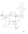
- a protection device 1 comprises a cut-off means 2 which is placed on a power conductor 3 connected to an AC supply network R, for example the network of a vehicle.
- the breaking means 2 is arranged upstream of a power circuit 4 which here comprises a power box 5 connected to a demining coil 6.
- a control box 7 is arranged upstream of the cutoff means 2. It controls the shape of the signals generated by the coil 6 and it comprises a man-machine interface for controlling the demining device.
- the device 1 also comprises a means 8 for measuring and analyzing the current intended to supply the power circuit 4.
- This measuring means 8 is connected to a triggering means 9 which makes it possible to control the opening of the breaking means 2.
- the measuring means 8 is designed so as to detect the appearance of a direct current in the power conductor 3.
- a display means 10 is also connected to the triggering means 9 and it makes it possible to highlight the open or closed state of the breaking means 2.
- This display means 10 may, for example, comprise two LEDs of different colors, a light color corresponding to the open position of the breaking means 2 and the other to the closed position.
- the figure 2 shows in a more precise way the organic and functional structure of the device 1.
- the means 8 for measuring and analyzing the current comprises two different modules: a logic module 12 and a measurement module 13.
- the logic module 12 incorporates a re-engagable monostable component 14 (for example a component known under the standard name 74HC4538).
- the logic output of this component alternates with a frequency which is that of the current flowing in the power conductor 3.
- This monostable 14 is connected to a state detector 15 (for example a flip-flop D) which makes it possible to identify a stop of the tilting of the monostable 14.
- the stop of this tilting corresponds to the stop of the oscillation of the current which means either that there is no current flowing in the power conductor 3, or that this current is continuous.
- the state detector 15 then provides an error signal (for example a transition to a logic state 1), which signal is applied to the tripping means 9 via an OR logic gate 16.
- the triggering means 9 then causes the opening of the breaking means 2.
- the state detector may be embodied as a specific electronic component (for example a component known under the standardized name 74HC74). It may simply consist of a software module incorporated in a computer, a module programmed to detect the stop of the oscillations of the output of the monostable 14. Such a computer may also be programmed to monitor forms of more complex currents .
- the triggering means 9 may for example be constituted by a control circuit of the opening of the breaking means 2. If the breaking means 2 is constituted by a static switch such as a thyristor, the triggering means 9 may be for example the electronic control circuit of the trigger of this thyristor.
- the measurement module 13 comprises a means 17 providing a measurement of the value of the current flowing in the supply network and the conductor 3.
- the current measuring components are well known to those skilled in the art and may be of analog technology or digital.
- the measurement module 13 also comprises a memory or register 18 inside which is incorporated a threshold value.
- the measurement module finally comprises a comparator 19 which compares the value measured by the means 17 with the threshold contained in the memory 18.
- the comparator is designed to deliver a signal (for example a logic state 1), which signal will be applied to the triggering means 9 via the logic gate 16.
- the memory 18 in the form of calibrated electronic components incorporated in an analog comparator 19 made for example in the form of a bridge.
- the breaking means 2 is actuated both when a level is excessive current than when the current changes from the alternating state to the continuous state.
- the device according to the invention also ensures a cut-off of the power circuits when the current is stopped. This improves the insulation and protection of the circuit outside the phases of use.
- a logic module 12 that can detect a continuous component superimposed on an oscillating signal. It will suffice to add at the level of the logic module 12, and parallel to the means 14 and 15, a stage comprising a filter eliminating the AC component followed by an evaluator measuring the DC component. This evaluator will include a comparator connected to another memory in which a threshold level of the DC component will be programmed.
- the various means constituting the device 1 will advantageously be made in whole or in part using a microprocessor or computer which will include software means to ensure on the one hand the comparison of the intensity level current with a preprogrammed threshold and secondly to detect the stop current oscillations.
- the invention has been described in its application to the protection of a demining coil. It can of course be applied to the protection of other types of electronic circuits degraded by direct current.
Landscapes
- Engineering & Computer Science (AREA)
- General Engineering & Computer Science (AREA)
- Physics & Mathematics (AREA)
- Acoustics & Sound (AREA)
- Electromagnetism (AREA)
- Emergency Protection Circuit Devices (AREA)
Priority Applications (1)
| Application Number | Priority Date | Filing Date | Title |
|---|---|---|---|
| EP07290482.4A EP1983295B1 (de) | 2007-04-19 | 2007-04-19 | Schutzvorrichtung für einen Schwingkreis zur Leistungsübertragung |
Applications Claiming Priority (1)
| Application Number | Priority Date | Filing Date | Title |
|---|---|---|---|
| EP07290482.4A EP1983295B1 (de) | 2007-04-19 | 2007-04-19 | Schutzvorrichtung für einen Schwingkreis zur Leistungsübertragung |
Publications (2)
| Publication Number | Publication Date |
|---|---|
| EP1983295A1 true EP1983295A1 (de) | 2008-10-22 |
| EP1983295B1 EP1983295B1 (de) | 2019-01-30 |
Family
ID=38754816
Family Applications (1)
| Application Number | Title | Priority Date | Filing Date |
|---|---|---|---|
| EP07290482.4A Not-in-force EP1983295B1 (de) | 2007-04-19 | 2007-04-19 | Schutzvorrichtung für einen Schwingkreis zur Leistungsübertragung |
Country Status (1)
| Country | Link |
|---|---|
| EP (1) | EP1983295B1 (de) |
Citations (6)
| Publication number | Priority date | Publication date | Assignee | Title |
|---|---|---|---|---|
| US2368084A (en) * | 1942-08-27 | 1945-01-30 | Gen Motors Corp | Protector |
| GB917896A (en) * | 1959-09-28 | 1963-02-06 | Philips Electrical Ind Ltd | Improvements in or relating to devices for safeguarding against pulsating direct current a load to be fed with alternating current |
| DE1965483A1 (de) * | 1969-12-30 | 1971-07-22 | Licentia Gmbh | Verfahren zur Stoerungsueberwachung einer nahezu rechteckfoermigen Wechselspannung |
| GB2143958A (en) * | 1983-07-26 | 1985-02-20 | Westinghouse Electric Corp | Tracking filter for sensing dc content in an ac waveform |
| US5060166A (en) * | 1989-12-06 | 1991-10-22 | Abb Power T&D Company Inc. | Method and apparatus for rapidly analyzing AC waveforms containing DC offsets |
| WO1997048965A1 (fr) * | 1996-06-19 | 1997-12-24 | Giat Industries | Bobine de deminage et dispositif de deminage en faisant application |
-
2007
- 2007-04-19 EP EP07290482.4A patent/EP1983295B1/de not_active Not-in-force
Patent Citations (7)
| Publication number | Priority date | Publication date | Assignee | Title |
|---|---|---|---|---|
| US2368084A (en) * | 1942-08-27 | 1945-01-30 | Gen Motors Corp | Protector |
| GB917896A (en) * | 1959-09-28 | 1963-02-06 | Philips Electrical Ind Ltd | Improvements in or relating to devices for safeguarding against pulsating direct current a load to be fed with alternating current |
| DE1965483A1 (de) * | 1969-12-30 | 1971-07-22 | Licentia Gmbh | Verfahren zur Stoerungsueberwachung einer nahezu rechteckfoermigen Wechselspannung |
| FR2073510A1 (de) * | 1969-12-30 | 1971-10-01 | Licentia Gmbh | |
| GB2143958A (en) * | 1983-07-26 | 1985-02-20 | Westinghouse Electric Corp | Tracking filter for sensing dc content in an ac waveform |
| US5060166A (en) * | 1989-12-06 | 1991-10-22 | Abb Power T&D Company Inc. | Method and apparatus for rapidly analyzing AC waveforms containing DC offsets |
| WO1997048965A1 (fr) * | 1996-06-19 | 1997-12-24 | Giat Industries | Bobine de deminage et dispositif de deminage en faisant application |
Also Published As
| Publication number | Publication date |
|---|---|
| EP1983295B1 (de) | 2019-01-30 |
Similar Documents
| Publication | Publication Date | Title |
|---|---|---|
| EP0537084B1 (de) | Schutzschalter mit selektiver Verriegelung | |
| EP3126783B1 (de) | Vorrichtung zur messung von mindestens einer physikalischen grösse einer elektrischen installation | |
| EP2139087B1 (de) | Schutzschalter mit verbesserter Wiederschließungsfunktion | |
| FR2621748A1 (fr) | Declencheur statique d'un disjoncteur a boitier moule | |
| EP2648008A1 (de) | Isolierungskontrollsystem für gesichertes Stromnetz | |
| KR102162207B1 (ko) | 로고스키 코일을 이용한 직류전류 측정장치 | |
| CA1187554A (fr) | Dispositifs portatifs de verification d'absence de tension sur les installations a haute et tres haute tension alternative | |
| CA2862849C (fr) | Dispositif et procede de securite pour installation electrique | |
| EP3399612A1 (de) | Elektrischer anschluss, der eine elektrische schutzvorrichtung zur stromvorspannung umfasst | |
| WO2019110711A1 (fr) | Procede de detection de l'etat d'un appareil de protection electrique dans une installation electrique et dispositif de detection mettant en oeuvre ledit procede | |
| EP2682972B1 (de) | Vorrichtung zur Erkennung des offenen oder geschlossenen Zustands eines Schalters, und Schutz-Relaisüberwachungsvorrichtung des entsprechenden Transformators | |
| EP0180501B1 (de) | Vorrichtung zur Feststellung und Festlegung eines Fehlers in einer Seilschwebebahneinrichtung | |
| EP1983295B1 (de) | Schutzvorrichtung für einen Schwingkreis zur Leistungsübertragung | |
| GB2238191A (en) | Intrinsically safe system | |
| FR2899395A1 (fr) | Dispositif de protection d'un circuit de puissance oscillant | |
| FR2512993A3 (fr) | Dispositif lumineux de signalisation d'incidents survenus dans des installations electriques domestiques | |
| KR100929499B1 (ko) | 자동 복구기능을 구비한 전원차단장치 | |
| FR3032276A1 (fr) | Capteur de courant et reseau electrique comprenant un tel capteur de courant | |
| EP3552034B1 (de) | Verfahren zur herstellung eines messsensors für einen leistungsschalter | |
| FR3116124A1 (fr) | Dispositifs de surveillance et de protection de circuits de puissance | |
| EP3297111B1 (de) | Vorrichtung und verfahren zur überwachung der aktivität der verarbeitungseinheiten in einem elektrischen auslöser | |
| FR2697343A1 (fr) | Appareil de contrôle pour prise de courant à contact de terre et protection différentielle. | |
| FR2601483A1 (fr) | Installation de surveillance comportant des detecteurs alimentes par une boucle | |
| EP3977577A1 (de) | Schutzvorrichtung für stromleitung (l) zum erkennen eines leckfehlers, kurzschlusses, fehlers, überstromfehlers und lichtbogenfehlers | |
| FR2696240A1 (fr) | Système de commutation autotestable. |
Legal Events
| Date | Code | Title | Description |
|---|---|---|---|
| PUAI | Public reference made under article 153(3) epc to a published international application that has entered the european phase |
Free format text: ORIGINAL CODE: 0009012 |
|
| AK | Designated contracting states |
Kind code of ref document: A1 Designated state(s): AT BE BG CH CY CZ DE DK EE ES FI FR GB GR HU IE IS IT LI LT LU LV MC MT NL PL PT RO SE SI SK TR |
|
| AX | Request for extension of the european patent |
Extension state: AL BA HR MK RS |
|
| 17P | Request for examination filed |
Effective date: 20090422 |
|
| 17Q | First examination report despatched |
Effective date: 20090520 |
|
| AKX | Designation fees paid |
Designated state(s): AT BE BG CH CY CZ DE DK EE ES FI FR GB GR HU IE IS IT LI LT LU LV MC MT NL PL PT RO SE SI SK TR |
|
| STAA | Information on the status of an ep patent application or granted ep patent |
Free format text: STATUS: EXAMINATION IS IN PROGRESS |
|
| REG | Reference to a national code |
Ref country code: DE Ref legal event code: R079 Ref document number: 602007057535 Country of ref document: DE Free format text: PREVIOUS MAIN CLASS: F41H0011120000 Ipc: F41H0011136000 |
|
| GRAP | Despatch of communication of intention to grant a patent |
Free format text: ORIGINAL CODE: EPIDOSNIGR1 |
|
| STAA | Information on the status of an ep patent application or granted ep patent |
Free format text: STATUS: GRANT OF PATENT IS INTENDED |
|
| RIC1 | Information provided on ipc code assigned before grant |
Ipc: H01F 7/18 20060101ALI20180808BHEP Ipc: F41H 11/136 20110101AFI20180808BHEP Ipc: B63G 7/06 20060101ALI20180808BHEP Ipc: F41H 11/16 20110101ALI20180808BHEP Ipc: F41H 11/12 20110101ALI20180808BHEP |
|
| INTG | Intention to grant announced |
Effective date: 20180823 |
|
| GRAS | Grant fee paid |
Free format text: ORIGINAL CODE: EPIDOSNIGR3 |
|
| GRAA | (expected) grant |
Free format text: ORIGINAL CODE: 0009210 |
|
| STAA | Information on the status of an ep patent application or granted ep patent |
Free format text: STATUS: THE PATENT HAS BEEN GRANTED |
|
| GRAF | Information related to payment of grant fee modified |
Free format text: ORIGINAL CODE: EPIDOSCIGR3 |
|
| AK | Designated contracting states |
Kind code of ref document: B1 Designated state(s): AT BE BG CH CY CZ DE DK EE ES FI FR GB GR HU IE IS IT LI LT LU LV MC MT NL PL PT RO SE SI SK TR |
|
| REG | Reference to a national code |
Ref country code: GB Ref legal event code: FG4D Free format text: NOT ENGLISH |
|
| REG | Reference to a national code |
Ref country code: CH Ref legal event code: EP |
|
| REG | Reference to a national code |
Ref country code: AT Ref legal event code: REF Ref document number: 1093631 Country of ref document: AT Kind code of ref document: T Effective date: 20190215 |
|
| REG | Reference to a national code |
Ref country code: IE Ref legal event code: FG4D Free format text: LANGUAGE OF EP DOCUMENT: FRENCH |
|
| REG | Reference to a national code |
Ref country code: DE Ref legal event code: R096 Ref document number: 602007057535 Country of ref document: DE |
|
| PGFP | Annual fee paid to national office [announced via postgrant information from national office to epo] |
Ref country code: FR Payment date: 20190325 Year of fee payment: 13 |
|
| REG | Reference to a national code |
Ref country code: NL Ref legal event code: FP |
|
| REG | Reference to a national code |
Ref country code: LT Ref legal event code: MG4D |
|
| PG25 | Lapsed in a contracting state [announced via postgrant information from national office to epo] |
Ref country code: LT Free format text: LAPSE BECAUSE OF FAILURE TO SUBMIT A TRANSLATION OF THE DESCRIPTION OR TO PAY THE FEE WITHIN THE PRESCRIBED TIME-LIMIT Effective date: 20190130 Ref country code: FI Free format text: LAPSE BECAUSE OF FAILURE TO SUBMIT A TRANSLATION OF THE DESCRIPTION OR TO PAY THE FEE WITHIN THE PRESCRIBED TIME-LIMIT Effective date: 20190130 Ref country code: SE Free format text: LAPSE BECAUSE OF FAILURE TO SUBMIT A TRANSLATION OF THE DESCRIPTION OR TO PAY THE FEE WITHIN THE PRESCRIBED TIME-LIMIT Effective date: 20190130 Ref country code: PT Free format text: LAPSE BECAUSE OF FAILURE TO SUBMIT A TRANSLATION OF THE DESCRIPTION OR TO PAY THE FEE WITHIN THE PRESCRIBED TIME-LIMIT Effective date: 20190530 Ref country code: ES Free format text: LAPSE BECAUSE OF FAILURE TO SUBMIT A TRANSLATION OF THE DESCRIPTION OR TO PAY THE FEE WITHIN THE PRESCRIBED TIME-LIMIT Effective date: 20190130 Ref country code: PL Free format text: LAPSE BECAUSE OF FAILURE TO SUBMIT A TRANSLATION OF THE DESCRIPTION OR TO PAY THE FEE WITHIN THE PRESCRIBED TIME-LIMIT Effective date: 20190130 |
|
| REG | Reference to a national code |
Ref country code: AT Ref legal event code: MK05 Ref document number: 1093631 Country of ref document: AT Kind code of ref document: T Effective date: 20190130 |
|
| PG25 | Lapsed in a contracting state [announced via postgrant information from national office to epo] |
Ref country code: LV Free format text: LAPSE BECAUSE OF FAILURE TO SUBMIT A TRANSLATION OF THE DESCRIPTION OR TO PAY THE FEE WITHIN THE PRESCRIBED TIME-LIMIT Effective date: 20190130 Ref country code: IS Free format text: LAPSE BECAUSE OF FAILURE TO SUBMIT A TRANSLATION OF THE DESCRIPTION OR TO PAY THE FEE WITHIN THE PRESCRIBED TIME-LIMIT Effective date: 20190530 Ref country code: GR Free format text: LAPSE BECAUSE OF FAILURE TO SUBMIT A TRANSLATION OF THE DESCRIPTION OR TO PAY THE FEE WITHIN THE PRESCRIBED TIME-LIMIT Effective date: 20190501 Ref country code: BG Free format text: LAPSE BECAUSE OF FAILURE TO SUBMIT A TRANSLATION OF THE DESCRIPTION OR TO PAY THE FEE WITHIN THE PRESCRIBED TIME-LIMIT Effective date: 20190430 |
|
| PG25 | Lapsed in a contracting state [announced via postgrant information from national office to epo] |
Ref country code: DK Free format text: LAPSE BECAUSE OF FAILURE TO SUBMIT A TRANSLATION OF THE DESCRIPTION OR TO PAY THE FEE WITHIN THE PRESCRIBED TIME-LIMIT Effective date: 20190130 Ref country code: EE Free format text: LAPSE BECAUSE OF FAILURE TO SUBMIT A TRANSLATION OF THE DESCRIPTION OR TO PAY THE FEE WITHIN THE PRESCRIBED TIME-LIMIT Effective date: 20190130 Ref country code: CZ Free format text: LAPSE BECAUSE OF FAILURE TO SUBMIT A TRANSLATION OF THE DESCRIPTION OR TO PAY THE FEE WITHIN THE PRESCRIBED TIME-LIMIT Effective date: 20190130 Ref country code: RO Free format text: LAPSE BECAUSE OF FAILURE TO SUBMIT A TRANSLATION OF THE DESCRIPTION OR TO PAY THE FEE WITHIN THE PRESCRIBED TIME-LIMIT Effective date: 20190130 Ref country code: SK Free format text: LAPSE BECAUSE OF FAILURE TO SUBMIT A TRANSLATION OF THE DESCRIPTION OR TO PAY THE FEE WITHIN THE PRESCRIBED TIME-LIMIT Effective date: 20190130 Ref country code: IT Free format text: LAPSE BECAUSE OF FAILURE TO SUBMIT A TRANSLATION OF THE DESCRIPTION OR TO PAY THE FEE WITHIN THE PRESCRIBED TIME-LIMIT Effective date: 20190130 |
|
| REG | Reference to a national code |
Ref country code: DE Ref legal event code: R097 Ref document number: 602007057535 Country of ref document: DE |
|
| PLBE | No opposition filed within time limit |
Free format text: ORIGINAL CODE: 0009261 |
|
| STAA | Information on the status of an ep patent application or granted ep patent |
Free format text: STATUS: NO OPPOSITION FILED WITHIN TIME LIMIT |
|
| REG | Reference to a national code |
Ref country code: BE Ref legal event code: MM Effective date: 20190430 |
|
| PG25 | Lapsed in a contracting state [announced via postgrant information from national office to epo] |
Ref country code: LU Free format text: LAPSE BECAUSE OF NON-PAYMENT OF DUE FEES Effective date: 20190419 Ref country code: AT Free format text: LAPSE BECAUSE OF FAILURE TO SUBMIT A TRANSLATION OF THE DESCRIPTION OR TO PAY THE FEE WITHIN THE PRESCRIBED TIME-LIMIT Effective date: 20190130 Ref country code: MC Free format text: LAPSE BECAUSE OF FAILURE TO SUBMIT A TRANSLATION OF THE DESCRIPTION OR TO PAY THE FEE WITHIN THE PRESCRIBED TIME-LIMIT Effective date: 20190130 |
|
| 26N | No opposition filed |
Effective date: 20191031 |
|
| PG25 | Lapsed in a contracting state [announced via postgrant information from national office to epo] |
Ref country code: SI Free format text: LAPSE BECAUSE OF FAILURE TO SUBMIT A TRANSLATION OF THE DESCRIPTION OR TO PAY THE FEE WITHIN THE PRESCRIBED TIME-LIMIT Effective date: 20190130 Ref country code: BE Free format text: LAPSE BECAUSE OF NON-PAYMENT OF DUE FEES Effective date: 20190430 |
|
| PG25 | Lapsed in a contracting state [announced via postgrant information from national office to epo] |
Ref country code: TR Free format text: LAPSE BECAUSE OF FAILURE TO SUBMIT A TRANSLATION OF THE DESCRIPTION OR TO PAY THE FEE WITHIN THE PRESCRIBED TIME-LIMIT Effective date: 20190130 |
|
| PG25 | Lapsed in a contracting state [announced via postgrant information from national office to epo] |
Ref country code: IE Free format text: LAPSE BECAUSE OF NON-PAYMENT OF DUE FEES Effective date: 20190419 |
|
| PG25 | Lapsed in a contracting state [announced via postgrant information from national office to epo] |
Ref country code: FR Free format text: LAPSE BECAUSE OF NON-PAYMENT OF DUE FEES Effective date: 20200430 |
|
| PGFP | Annual fee paid to national office [announced via postgrant information from national office to epo] |
Ref country code: CH Payment date: 20210326 Year of fee payment: 15 Ref country code: NL Payment date: 20210329 Year of fee payment: 15 |
|
| PG25 | Lapsed in a contracting state [announced via postgrant information from national office to epo] |
Ref country code: CY Free format text: LAPSE BECAUSE OF FAILURE TO SUBMIT A TRANSLATION OF THE DESCRIPTION OR TO PAY THE FEE WITHIN THE PRESCRIBED TIME-LIMIT Effective date: 20190130 |
|
| PGFP | Annual fee paid to national office [announced via postgrant information from national office to epo] |
Ref country code: GB Payment date: 20210324 Year of fee payment: 15 |
|
| PG25 | Lapsed in a contracting state [announced via postgrant information from national office to epo] |
Ref country code: HU Free format text: LAPSE BECAUSE OF FAILURE TO SUBMIT A TRANSLATION OF THE DESCRIPTION OR TO PAY THE FEE WITHIN THE PRESCRIBED TIME-LIMIT; INVALID AB INITIO Effective date: 20070419 Ref country code: MT Free format text: LAPSE BECAUSE OF FAILURE TO SUBMIT A TRANSLATION OF THE DESCRIPTION OR TO PAY THE FEE WITHIN THE PRESCRIBED TIME-LIMIT Effective date: 20190130 |
|
| PGFP | Annual fee paid to national office [announced via postgrant information from national office to epo] |
Ref country code: DE Payment date: 20210323 Year of fee payment: 15 |
|
| REG | Reference to a national code |
Ref country code: DE Ref legal event code: R119 Ref document number: 602007057535 Country of ref document: DE |
|
| REG | Reference to a national code |
Ref country code: CH Ref legal event code: PL |
|
| REG | Reference to a national code |
Ref country code: NL Ref legal event code: MM Effective date: 20220501 |
|
| GBPC | Gb: european patent ceased through non-payment of renewal fee |
Effective date: 20220419 |
|
| PG25 | Lapsed in a contracting state [announced via postgrant information from national office to epo] |
Ref country code: NL Free format text: LAPSE BECAUSE OF NON-PAYMENT OF DUE FEES Effective date: 20220501 Ref country code: LI Free format text: LAPSE BECAUSE OF NON-PAYMENT OF DUE FEES Effective date: 20220430 Ref country code: GB Free format text: LAPSE BECAUSE OF NON-PAYMENT OF DUE FEES Effective date: 20220419 Ref country code: DE Free format text: LAPSE BECAUSE OF NON-PAYMENT OF DUE FEES Effective date: 20221103 Ref country code: CH Free format text: LAPSE BECAUSE OF NON-PAYMENT OF DUE FEES Effective date: 20220430 |