EP3126783B1 - Vorrichtung zur messung von mindestens einer physikalischen grösse einer elektrischen installation - Google Patents
Vorrichtung zur messung von mindestens einer physikalischen grösse einer elektrischen installation Download PDFInfo
- Publication number
- EP3126783B1 EP3126783B1 EP15719789.8A EP15719789A EP3126783B1 EP 3126783 B1 EP3126783 B1 EP 3126783B1 EP 15719789 A EP15719789 A EP 15719789A EP 3126783 B1 EP3126783 B1 EP 3126783B1
- Authority
- EP
- European Patent Office
- Prior art keywords
- sensor
- current
- conductors
- pair
- voltage
- Prior art date
- Legal status (The legal status is an assumption and is not a legal conclusion. Google has not performed a legal analysis and makes no representation as to the accuracy of the status listed.)
- Active
Links
Images


Classifications
-
- G—PHYSICS
- G01—MEASURING; TESTING
- G01R—MEASURING ELECTRIC VARIABLES; MEASURING MAGNETIC VARIABLES
- G01R19/00—Arrangements for measuring currents or voltages or for indicating presence or sign thereof
-
- G—PHYSICS
- G01—MEASURING; TESTING
- G01R—MEASURING ELECTRIC VARIABLES; MEASURING MAGNETIC VARIABLES
- G01R15/00—Details of measuring arrangements of the types provided for in groups G01R17/00 - G01R29/00, G01R33/00 - G01R33/26 or G01R35/00
- G01R15/14—Adaptations providing voltage or current isolation, e.g. for high-voltage or high-current networks
- G01R15/18—Adaptations providing voltage or current isolation, e.g. for high-voltage or high-current networks using inductive devices, e.g. transformers
-
- G—PHYSICS
- G01—MEASURING; TESTING
- G01D—MEASURING NOT SPECIALLY ADAPTED FOR A SPECIFIC VARIABLE; ARRANGEMENTS FOR MEASURING TWO OR MORE VARIABLES NOT COVERED IN A SINGLE OTHER SUBCLASS; TARIFF METERING APPARATUS; MEASURING OR TESTING NOT OTHERWISE PROVIDED FOR
- G01D21/00—Measuring or testing not otherwise provided for
- G01D21/02—Measuring two or more variables by means not covered by a single other subclass
-
- G—PHYSICS
- G01—MEASURING; TESTING
- G01D—MEASURING NOT SPECIALLY ADAPTED FOR A SPECIFIC VARIABLE; ARRANGEMENTS FOR MEASURING TWO OR MORE VARIABLES NOT COVERED IN A SINGLE OTHER SUBCLASS; TARIFF METERING APPARATUS; MEASURING OR TESTING NOT OTHERWISE PROVIDED FOR
- G01D3/00—Indicating or recording apparatus with provision for the special purposes referred to in the subgroups
- G01D3/02—Indicating or recording apparatus with provision for the special purposes referred to in the subgroups with provision for altering or correcting the law of variation
- G01D3/022—Indicating or recording apparatus with provision for the special purposes referred to in the subgroups with provision for altering or correcting the law of variation having an ideal characteristic, map or correction data stored in a digital memory
-
- G—PHYSICS
- G01—MEASURING; TESTING
- G01R—MEASURING ELECTRIC VARIABLES; MEASURING MAGNETIC VARIABLES
- G01R15/00—Details of measuring arrangements of the types provided for in groups G01R17/00 - G01R29/00, G01R33/00 - G01R33/26 or G01R35/00
- G01R15/14—Adaptations providing voltage or current isolation, e.g. for high-voltage or high-current networks
- G01R15/18—Adaptations providing voltage or current isolation, e.g. for high-voltage or high-current networks using inductive devices, e.g. transformers
- G01R15/181—Adaptations providing voltage or current isolation, e.g. for high-voltage or high-current networks using inductive devices, e.g. transformers using coils without a magnetic core, e.g. Rogowski coils
-
- G—PHYSICS
- G01—MEASURING; TESTING
- G01R—MEASURING ELECTRIC VARIABLES; MEASURING MAGNETIC VARIABLES
- G01R31/00—Arrangements for testing electric properties; Arrangements for locating electric faults; Arrangements for electrical testing characterised by what is being tested not provided for elsewhere
-
- G—PHYSICS
- G01—MEASURING; TESTING
- G01R—MEASURING ELECTRIC VARIABLES; MEASURING MAGNETIC VARIABLES
- G01R31/00—Arrangements for testing electric properties; Arrangements for locating electric faults; Arrangements for electrical testing characterised by what is being tested not provided for elsewhere
- G01R31/50—Testing of electric apparatus, lines, cables or components for short-circuits, continuity, leakage current or incorrect line connections
- G01R31/66—Testing of connections, e.g. of plugs or non-disconnectable joints
- G01R31/67—Testing the correctness of wire connections in electric apparatus or circuits
Definitions
- the present invention relates to a device for measuring at least one physical quantity of an electrical installation, comprising at least one sensor arranged to measure at least said physical quantity and deliver at least one signal representative of said physical quantity, and at least one measurement unit arranged to receive said signal and process it to deliver at least one exploitable measurement value, said sensor and said measurement unit being connected together by at least one connection cable, said connection cable comprising at least three pairs of conductors, a first pair of conductors, called measurement pair, arranged to transmit said signal representative of said physical quantity measured by said sensor, a second pair of conductors, called supply pair, arranged to electrically supply said sensor by said unit and a third pair of conductors, called a communication pair ion, arranged to transmit at least one complementary signal between said sensor and said measurement unit, and said sensor comprising encoding means arranged to characterize said sensor and transmit to said measurement unit via said communication pair at least one complementary signal corresponding to at least one identification characteristic of said sensor.
- the configuration and verification phase of the installation is often a source of errors, in particular on three-phase networks.
- this implementation requires placing current and / or voltage sensors on the conductors or phases of the electrical installation and connecting these sensors to measurement units who can be deported. Consequently, the errors made in this installation phase are mainly due to improper connection of the current measurement channels and the voltage measurement channels between the sensors and the measurement units, to a sensor rating declared to be incorrect, to reverse polarity of current sensors, etc. These errors are sometimes difficult to correct and can even go unnoticed for some time, which can lead to false measurement values and therefore to incorrect decisions in the management of the electrical installation.
- the publication EP 0 324 067 describes a measurement sensor provided with a transducer and an evaluation module in which sensor identification data are stored. These identification data are transmitted via connection lines normally used for measurement and power supply. These identification data are therefore superimposed on the measurement data and are necessarily digital.
- the coupling scheme is relatively complex and uses a bidirectional digital link using several distinct signals.
- the publication US 2014/0022082 describes a method and apparatus for identifying and locating current sensors.
- Measuring equipment includes at least one current sensor measuring current on a conductor of the electrical installation, and communicating with a base unit through a connection cable provided with two pairs of conductors, a first pair for the transmission of the current measurement signal and a second pair for the identification of the sensor by means of a resistor whose value is chosen according to said sensor.
- This measuring device is limited to the recognition of simple analog sensors and its encoding possibilities are very limited.
- the publication US 2004/0034658 corresponds to the preamble of claim 1 and describes a “Plug and Play” sensor provided with a transducer carrying out analog measurements and with a TEDS electronic data card containing the digital identification data of said sensor.
- This sensor communicates with a measurement unit through a communication interface in mixed analog / digital mode, comprising three pairs of conductors, a first pair of which is used to transmit the analog measurement signal, a second pair to supply the sensor , and a third pair for the transmission of digital sensor identification data.
- the measurement unit can only recognize sensors with digital encoding.
- connection correction cannot therefore be carried out easily before commissioning, even though the electrical panels are often pre-wired before even being delivered. It would therefore be advantageous to be able to verify that all of the wiring has been correctly carried out before putting the electrical installation into service.
- the present invention aims to overcome these drawbacks by proposing an intelligent, modular, economical measurement device, suitable for both simple analog sensors and advanced digital sensors, with the aim of improving the quality and precision of measurements without increase the cost of the sensors or by using inexpensive sensors, by making possible the automatic recognition of the sensors whatever their type by the measuring devices, making it possible to control the correct functioning of the sensors and to avoid errors in transcription of the caliber of sensors, the type of sensors, wiring errors, as well as fraud by detecting the absence of a sensor in particular.
- the invention relates to a measuring device according to independent claim 1.
- the sensor is analog, then it advantageously comprises two resistors, the resistance values of which are chosen as a function of at least one characteristic identifying said sensor.
- the measurement unit comprises two other resistors arranged to form with the two resistors of said sensor, two dividing bridges connected on the one hand to said supply pair and on the other hand to said communication pair to deliver to the terminals of said communication pair at least one additional voltage signal in analog form representative of said identification characteristic of said sensor.
- the senor is digital, then it advantageously comprises a processing unit in which at least one identification characteristic of said sensor is recorded, this processing unit being connected on the one hand to said power supply pair and on the other hand to at least one of the conductors of the pair of communication to deliver at least one complementary signal in digital form representative of said identification characteristic of said sensor.
- the encoding means can be arranged to transmit to said measurement unit via said communication pair several complementary signals corresponding to several identification characteristics of said sensor allowing said measurement unit to recognize said sensor, these identification characteristics being able to be chosen from the group comprising the nominal sensor voltage, the nominal sensor current, the sensor calibration data, the sensor gain error compensation curve, the sensor phase error compensation curve.
- Said measurement unit may further comprise two resistors connected respectively between the conductors of said measurement and supply pairs to polarize the conductors of said measurement pair and detect the presence of said sensor.
- the communication pair can be arranged to convey on one of its conductors at least a first complementary signal representative of at least one identification characteristic of said sensor and on the other of its conductors at least a second complementary signal corresponding to an auxiliary physical quantity of said electrical installation.
- the senor is a current sensor arranged to measure the current on one of the conductors of said electrical installation.
- the measuring device may comprise at least one auxiliary voltage sensor arranged to measure an auxiliary voltage value representative of the voltage present on the conductor, the current of which is measured by said current sensor, this value of auxiliary voltage forming an auxiliary physical quantity conveyed on one of the conductors of said communication pair.
- This auxiliary voltage sensor can be integrated into said current sensor or connected in series between said current sensor and said measurement unit and connected to each of them by at least one connection cable.
- This auxiliary voltage sensor may include at least one selector arranged to automatically reverse the direction of connection of said auxiliary voltage sensor between said current sensor and said measurement unit in the event of a connection error.
- the current sensor can comprise at least one earth leakage current sensor at very low frequency relative to the frequency of the network supplying said electrical installation, arranged to measure a leakage current value at earth with a bandwidth including at least the frequency of the supply network, this value of earth leakage current forming an auxiliary physical quantity carried on one of the conductors of said communication pair.
- the current sensor can comprise at least one temperature sensor arranged to measure the temperature of said current sensor, this temperature forming an auxiliary physical quantity conveyed on one of the conductors of said communication pair.
- the current sensor can comprise at least one additional current sensor arranged to perform a second current measurement on the conductor of said electrical installation, this second current measurement forming a physical quantity conveyed on one of the conductors of said communication pair to verify the proper functioning of said current sensor by comparison of this second current measurement with that carried out by said current sensor.
- the measurement unit comprises a processing unit containing at least one correspondence table between identification characteristics and sensors, and the processing unit is connected to said communication pair to receive at least the signal complementary representative of said identification characteristic allowing it to automatically recognize the sensor which is connected to said measurement unit and to deliver an exploitable correlated value of said measured physical quantity.
- the measuring device advantageously comprises N current sensors, each provided with an auxiliary voltage sensor, and N voltage sensors arranged to measure respectively the current and the voltage on N conductors of said electrical installation.
- the measurement unit may include a correlation module arranged to match the voltage measurement which corresponds to the measurement of the auxiliary voltage carried out on the same conductor of said electrical installation and automatically compensate for any connection errors of said sensors.
- the object of the invention is also achieved by using the measuring device described above to detect an attempted fraud on said measuring device by detecting an inconsistency on the signals transmitted via said connection cable between said sensor and said unit of measure.
- the object of the invention is also achieved by the use of the measuring device to detect the opening of a cut-off device arranged upstream of an electrical installation if on the one hand the voltage sensor is connected upstream of said cut-off device and if, on the other hand, the current sensor provided with its auxiliary voltage sensor is connected downstream of said cut-off device.
- the measurement device 10-13 comprises a sensor 20, 20 ′ arranged to measure at least one physical quantity of an electrical installation and a measurement unit 40 coupled to said sensor 20, 20 ′ by a particular connection cable 50.
- the sensor is in the example described and illustrated a current sensor 20, 20 'arranged to measure the current on one of the conductors L1 of the electrical installation, but may concern any other type of sensor.
- the current sensor 20, 20 ′ uses existing technologies, such as a current transformer, a Rogowski loop, sensors based on magnetic field measurement such as the Hall effect or the “Fluxgate” system, or the like, and delivers a signal representative of the measured current, this signal generally being of analog form.
- This sensor 20, 20 ′ can be either a simple analog sensor or an advanced digital sensor.
- the measurement unit 40 is designed to be able to be connected to any type of sensor 20, 20 ′ and thus constitutes an identical standard module for each of the configurations illustrated in the figures. It includes in particular a processing unit 45, shown only on the figure 1 but present in all the embodiments according to the figures 2 to 4 .
- This processing unit 45 is programmable and is arranged to receive the signal from said current sensor 20, 20 '.
- the processing unit 45 also makes it possible to process and exploit the signal in order to display a measurement value which can be used by an operator and / or a supervisory unit which can be offset, such as a current value , power, energy, power factor, harmonic analysis of currents and / or powers, etc.
- connection cable 50 used to connect the current sensor 20, 20 'and the measurement unit 40 is a modular cable which has six positions and six contacts, usually known as the RJ12 cable or any similar cable.
- This type of RJ12 cable also called Registered Jack 12
- RJ12 cable also called Registered Jack 12
- This type of RJ12 cable is an international standard used by landline telephones. It is also used in the area of local area networks. It has three pairs of conductors 51, 52, 53.
- a first pair of conductors 51 is used for the differential transmission of an analog signal representative of a quantity to be measured coming from said current sensor 20, 20 ′, is called by the continuation “measurement pair”, and is connected to the processing unit 45.
- a second pair of conductors 52 is used to supply the sensor 20, 20 ′ by the measurement unit 40, and is called subsequently "Power pair".
- a third pair of conductors 53 is used to transmit information complementary in the form of signals DET1, DET2 indifferently analog and digital between the current sensor 20, 20 ′ and the measurement unit 40, is called hereinafter “communication pair” and is connected to the processing unit 45
- communication pair is connected to the processing unit 45
- any other connection system comprising at least three pairs of conductors can be used.
- the conductors 51+, 51- of the measurement pair 51 are biased by the measurement unit 40 using two resistors 41, 42 of high value relative to the maximum output resistance of the current sensor 20, 20 '.
- a first resistor 41 is connected between one of the conductors 51+ of the measurement pair 51 and the conductor 52+ of positive polarity of the power pair 52
- the second resistor 42 is connected between the second conductor 51- of the pair 51 and the conductor 52- of negative polarity of the power pair 52.
- the differential voltage on the pair of measure 51 is the image of the signal to be measured. Since the measuring device 10-13 is intended for the measurement of alternating signals, the measurement of the average value of this differential voltage signal consequently makes it possible to detect the presence of a current sensor 20, 20 ′.
- the figure 1 illustrates a first embodiment of the measuring device 10 according to the invention comprising a simple analog current sensor 20, said to be passive, constituted by a current transformer, the primary circuit 21 of which is formed by the conductor L1 of the electrical installation to be checked and the secondary circuit 22 is coupled to the measurement pair 51.
- This measurement device 10 comprises encoding means 23, 24 and 25, 26 of said current sensor 20 provided respectively in said sensor 20 and in said unit of measure 40.
- the communication pair 53 is used to form two voltage dividing bridges by means two pairs of resistors 23, 24 and 25, 26, present respectively in the current sensor 20 and in the measurement unit 40.
- each conductor 53a, 53b of this communication pair 53 there is on each conductor 53a, 53b of this communication pair 53, a resistor 25, 26 located in the measurement unit 40 between the conductor 53a, 53b and the positive polarity 52+ of the power pair 52, and a resistor 23, 24 located in the current sensor 20 between the conductor 53a , 53b and the negative polarity 52- of the supply pair 52.
- the divider bridge 23, 25 generates a voltage signal DET1
- the divider bridge 24, 26 generates a voltage signal DET2.
- the signals DET1 and DET2 take the value of the supply voltage and, in the presence of a sensor 20, the signals DET1 and DET2 take the analog values between 0 and the voltage d 'food.
- the value of the voltage between each conductor 53a, 53b and the conductor 52- of negative polarity or the conductor 52+ of positive polarity of the supply voltage depends on the value of the resistors 23-26 forming the two dividing bridges voltage and, to a certain extent, the resistance of the conductors 53a, 53b of the communication pair 53.
- the resistors 23-26 high values , typically from a few kOhms to a few tens of kOhms, with respect to the resistances of the conductors 53a, 53b, typically from a few fractions of Ohms to a few tens of Ohms.
- This voltage on the conductors 53a, 53b of the communication pair 53 is converted into a digital value using an analog / digital converter (not shown) integrated in the processing unit 45 of the measurement unit 40.
- an analog / digital converter (not shown) integrated in the processing unit 45 of the measurement unit 40.
- the more different levels are chosen the greater the richness of coding, but the higher the sensitivity to disturbances and to the length of the cables.
- these voltage levels are distributed between 0V and the supply voltage to provide maximum immunity to disturbances.
- This encoding method allows you to include non-exhaustive the nominal size of the current sensor 20 by choosing the value of the resistors 23, 24 as a function of said size. Given the relatively small number of sizes to be encoded, i.e. between ten and thirty current sensor sizes useful to cover market needs, one can also use the relatively large number of encoding possibilities to identify other information, such as a typical compensation curve for gain and phase errors by current sensor model. One can imagine for the same current sensor rating, several manufacturing technologies, depending on the desired performance. A current transformer with an Iron / Silicon core will be less expensive than a transformer of the same caliber with an Iron / Nickel core but will also be less precise. The compensation curve to be applied is therefore not only a function of the size but also of the technology chosen.
- the processing unit 45 is programmable and includes in particular a table of correspondences between identification characteristics and current sensors 20, 20 ′ making it possible to correlate with the complementary signals DET1, DET2 which it receives via the pair of communication 53 allowing it to automatically recognize the type of current sensor 20, 20 ′ connected to said measurement unit 40 and therefore to deliver a correlable exploitable value of the physical quantity measured by said current sensor 20, 20 ′.
- the analog converter / digital (not shown) integrated in the processing unit 45 provides either a digital value making it possible to determine the resistance ratio 23/25 and 24/26 if the sensor 20 is analog, or by comparison with a threshold with or without hysteresis a sequence of binary values if the sensor 20 ′ is digital, includes the processing unit 60 and transmits the identification data in the form e of binary data sequence.
- the figure 2 illustrates a second embodiment of the measuring device 11 according to the invention provided with a digital advanced current sensor 20 ′, comprising a Rogowski loop 27 crossed by the conductor L1 of the electrical installation to be checked, and associated with a integrator 28, powered by conductors 52+, 52- of the supply pair 52, and the outputs of which are connected to the conductors 51+, 51-of the measurement pair 51 connected to the processing unit 45 (not shown in this figure).
- a digital advanced current sensor 20 ′ comprising a Rogowski loop 27 crossed by the conductor L1 of the electrical installation to be checked, and associated with a integrator 28, powered by conductors 52+, 52- of the supply pair 52, and the outputs of which are connected to the conductors 51+, 51-of the measurement pair 51 connected to the processing unit 45 (not shown in this figure).
- an auxiliary voltage sensor 30 is integrated in the current sensor 20 ′ and arranged to measure an auxiliary voltage value image of the voltage of the conductor L1 of the electrical installation on which the current sensor 20, 20 ′ is installed, using existing technologies, such as a capacitive measurement, an electric field measurement, a resistive measurement, or the like, and to deliver a signal representative of the measured voltage, this signal generally being of analog form.
- the auxiliary voltage sensor 30 illustrated uses a capacitive measurement by means of an electrode 31 for non-contact voltage detection disposed near the conductor L1 of said installation, associated with a capacitor 33 connected to the negative conductor 52- of the pair of power supply 52 and to an amplifier 32, supplied by the conductors 52+, 52- of the supply pair 52 and connected to one of the conductors 53b of the communication pair 53 to transmit a signal DET2 representative of the measured voltage, this signal generally being of analog form.
- the resistors 23, 24 making it possible to characterize the current sensor 20 of the previous example, are replaced by a processing unit 60, typically a programmable microcontroller, supplied by the conductors 52+, 52- of the supply pair 52.
- This processing unit 60 is used to transmit on one of the conductors 53a of the communication pair 53 complementary signals DET1 in digital form corresponding to the identification characteristics of the current sensor 20 'connected to the unit of measurement 40. These identification characteristics can be information on the nominal size, a serial number and calibration data allowing precise compensation of the gain and phase errors due to the current sensor 20 'as such. and no longer by current sensor model, as in the previous example.
- This processing unit 60 also makes it possible to transmit interesting additional information such as the temperature of the current sensor 20 ′ and of the auxiliary voltage sensor 30 for example. In this case, a temperature sensor should be added to the current sensor 20, 20 '.
- the current sensor 20 ′ consists of a Rogowski loop 27 associated with its integrator 28, as is the case in the figure 2 , it is known that it is very difficult to guarantee the precision and the reproducibility by construction of this type of current sensor, because of the mechanical tolerances and the tolerances on the values of the components. On the other hand, it is also known that it is relatively easy to measure these errors in order to then record them in the processing unit 60 of the current sensor 20 'in order to take them into account during the measurements and to compensate or correct the measurements by result.
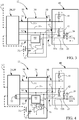
- the figure 3 illustrates a third embodiment of the measuring device 12 according to the invention provided with an auxiliary voltage sensor 30 separate from the current sensor which can be either a simple analog current sensor 20 according to the figure 1 or a 20 'digital advanced current sensor according to the figure 2 .
- the auxiliary voltage sensor 30 is mounted in series between the current sensor 20, 20 'and the measurement unit 40 by means of two connection cables 50 with six positions.
- the figure 4 illustrates a fourth embodiment of the measuring device 13 according to the invention, similar to that of the figure 3 , but comprising a selector 70 to make the auxiliary voltage sensor 30 reversible automatically simplified the work of the operator.
- the auxiliary voltage sensor 30 being connected between the current sensor 20, 20 ′ and the measurement unit 40, the operator can make the wrong direction of connection since the plugs of the connection cables 50 are identical.
- the processing unit 60 provided in the auxiliary voltage sensor 30 is arranged to detect the direction of connection and automatically switch the selector 70 to reverse the direction of connection in the event of a connection error.
- the measuring device 10-13 as just described is versatile and has intelligent functions. It is in particular capable of differentiating a simple analog current sensor 20, whose encoding is carried out by simple resistors 23 to 26, from a digital advanced current sensor 20 'whose encoding is carried out by a processing unit 60.
- the processing unit 45 provided in the measurement unit 40 is arranged to detect activity, by the presence of a binary signal DET1, on the conductor 53a of the communication pair 53 possibly supporting digital transmission in the case of a digital advanced current sensor 20 '.
- the measurement device 11-13 comprises a digital advanced current sensor 20 ′, for example according to the figure 2
- one of the two conductors 53b of the communication pair 53 is unused. It is advantageous and non-exhaustive to use this conductor 53b available to transmit an additional analog signal DET2 which can be used by the processing unit 45 and making it possible to improve its knowledge of the environment of the current sensor 20 ', or use this conductor 53b for transmitting information to the current sensor 20 ′, for example for making a measurement campaign by changing the nominal size of the current sensor 20 ′ if it offers this possibility.
- this additional signal DET2 can be an auxiliary voltage signal image of the voltage of the conductor L1 of the electrical installation whose current is measured, as the auxiliary voltage sensor 30 allows.
- This auxiliary voltage signal can be very imprecise in amplitude since it is not used to measure the actual voltage on the conductor L1, but its shape must be close to the real voltage signal and the time difference with the real voltage signal must be relatively small, of the order of a few degrees of phase shift relative to the frequency of the network equal for example to 50Hz.
- the processing unit 45 of the measurement unit 40 may comprise a correlation module making it possible to automatically detect which is the voltage channel which corresponds to the current sensor 20 ′ provided with an auxiliary voltage sensor 30, by searching for which nominal voltages V1, V2, V3 connected to the processing unit 45 has the maximum correlation with the auxiliary voltage signal Vaux.
- the figure 5 illustrates an example of connection between the three phases L1, L2, L3 of the electrical installation and the voltage channels V1, V2, V3 on the one hand and the current channels I1, I2, I3 on the other hand processing unit 45.
- the voltage channels V1, V2, V3 are coupled to voltage sensors 30 ′, for example in direct connection to measure the actual voltage on each of the phases.
- a connection inversion was voluntarily introduced between phases L2 and L3 on the voltage channels V2 and V3.
- the diagram of the figure 6 shows by way of example the correlation between the auxiliary signal Vaux obtained by the auxiliary voltage sensor 30 and the voltage channel V1 corresponding to phase L1 of the installation on which the current sensor 20 'is installed and connected to the channel I1 of the processing unit 45.
- this correlation method can be carried out automatically on the other phases L2 and L3 if the current sensors 20 ′ are provided with an auxiliary voltage sensor 30.
- the auxiliary signal Vaux image of the voltage on one of the conductors L1 on which the intensity is measured, can also be used to detect the opening of a breaking device (such as a circuit breaker) or the blowing of a fuse to trigger an alert or the like, if the voltage sensors 30 'supplying the voltage channels V1, V2, V3 of the processing unit 45 are connected to the phases L1, L2, L3 upstream of the device for break and if the current sensors 20 ' comprising an auxiliary voltage sensor 30 are connected downstream of said breaking device.
- a breaking device such as a circuit breaker
- the measuring device 10-13 uses electrical and electronic components available on the market. It is made intelligent thanks to the integration of programmable processing units 45, 60 and to an indifferent analog and digital communication between the current sensors 20, 20 ′ and the measurement unit 40 which constitutes a standardized module. Therefore, the measurement device 10-13 is modular, versatile and adapts to any type of current sensor 20, 20 ′ automatically, and in the same way to any other type of equivalent sensor. This design opens up new perspectives for exploiting the physical quantities of an electrical installation and thus allows multiple applications tending towards greater security and better reliability of the measured data.
- this measurement device 10-13 is capable of detecting the absence of a current sensor thanks to the resistors 41, 42 provided in the measurement unit 40, the nominal rating of a current sensor, the replacement a current sensor by checking the serial number, the inconsistencies between the voltages measured directly by the measuring device 40 connected to the current sensor (s) 20, 20 ′, said measuring device 40 being in fact an energy meter, and those detected by the auxiliary voltage sensor 30, etc.
- the use of an auxiliary signal can also make it possible to improve the reliability of the search for earth faults in electrical installations isolated from earth.
- the current sensor includes an earth leakage current sensor.
- the signal useful for measuring resistive earth faults is generally a very low frequency current signal, of small amplitude, which is often superimposed on a current signal present on the conductor at the network frequency, of much higher amplitude.
- a low-pass filtering of the overall signal is carried out in order to be able to correctly amplify the current signal at very low frequency.
- the earth leakage current signal of the installation to be checked may have a component at the network frequency (50Hz for example) which can be of much greater amplitude than the low frequency component transmitted on the pair. 51.
- This component at the network frequency can provide interesting information, in particular to check the absence of saturation of the earth leakage current sensor and that the earth leakage current sensor is well used in a current range compatible with the earth fault resistive fault finding application.
- the conductor 53b of the communication pair 53 can therefore be used to provide the unfiltered image of the earth leakage current and to trigger an alert if necessary.
- auxiliary signal can be a signal providing information on the same physical quantity as that already measured, for example a current signal, but obtained in a different and less precise manner by a good additional current sensor. market.
- the comparison of two signals representative of the same physical quantity can make it possible to detect a failure of the main current sensor 20, 20 ′ and therefore finds its place in measuring devices 10-13 for which operating safety is an important criterion. .
Landscapes
- Physics & Mathematics (AREA)
- General Physics & Mathematics (AREA)
- Engineering & Computer Science (AREA)
- Power Engineering (AREA)
- Technology Law (AREA)
- Arrangements For Transmission Of Measured Signals (AREA)
- Measuring Instrument Details And Bridges, And Automatic Balancing Devices (AREA)
Claims (18)
- Vorrichtung zur Messung (10-13) mindestens einer physikalischen Größe einer elektrischen Installation, mit mindestens einem Sensor (20, 20'), vorgesehen zur Messung mindestens dieser physikalischen Größe und zur Lieferung mindestens eines für diese physikalische Größe repräsentativen Signals, und mindestens einer Messeinheit (40), die zum Empfang dieses Signals und zu seiner Verarbeitung zur Lieferung mindestens eines nutzbaren Messwertes vorgesehen ist, wobei dieser Sensor und diese Messeinheit miteinander durch mindestens ein Verbindungskabel (50) verbunden sind, wobei dieses Verbindungskabel (50) mindestens drei Leiterpaare enthält: das erste dieser Leiterpaare (51+, 51-), Messpaar (51) genannt, das zur Übertragung dieses für die genannte, von diesem Sensor (20, 20') gemessene physikalischen Größe repräsentativen Signals vorgesehen ist, ein zweites Leiterpaar (52+, 52-), Versorgungspaar (52) genannt, das für die Stromversorgung dieses Sensors (20, 20') über diese Messeinheit (40) vorgesehen ist, und ein drittes Leiterpaar (53a, 53b), Kommunikationspaar (53) genannt, das zur Übertragung mindestens eines komplementären Signals (DET1, DET2) zwischen diesem Sensor (20, 20') und dieser Messeinheit (40) vorgesehen ist, wobei dieser Sensor (20, 20') dabei Kodiermittel (23, 24; 60) enthält, die zur Charakterisierung dieses Sensors und zur Übertragung an die genannte Messeinheit (40) über das genannte Kommunikationspaar (53) mindestens eines komplementären Signals (DET1, DET2) vorgesehen ist, das mindestens ein Identifikationsmerkmal des genannten Sensors enthält, wobei diese Messeinheit (40) außerdem Kodiermittel (25, 26) enthält, die komplementär zu den Kodiermitteln (23, 24, 60) sind, die im genannten Sensor (20, 20') vorgesehen sind,
dadurch gekennzeichnet, dass die genannte Messvorrichtung (10-13) modular ist und sich sowohl für einen einfachen analogen Sensor (20) eignet, wie für einen entwickelten digitalen Sensor (20'), dadurch, dass die genannte Messeinheit (40) zur Verbindung mit jedem Sensortyp (20, 20') konzipiert ist und ein Standardmodul bildet, und dadurch, dass diese Messeinheit (40) außerdem eine Verarbeitungseinheit (45) enthält, in die ein Analog/ Digital-Wandler integriert ist, der mit diesem Kommunikationspaar (53) zum Empfang und der Verarbeitung dieses mindestens einen komplementären Signals (DET1, DET2) verbunden ist, das auf mindestens einen der Leiter (53a, 53b) dieses Kommunikationspaars (53) übertragen wird, wobei es sich bei diesem Signal dabei gleichermaßen um ein analoges oder ein digitales Signal handeln kann und es repräsentativ für mindestens ein Identifikationsmerkmal dieses Sensors ist, das es dieser Messeinheit (40) ermöglicht, bei der Erkennung des Sensors (20, 20') automatisch zwischen einem einfachen analogen Sensor (20) und einem entwickelten digitalen Sensor (20') zu unterscheiden, der an diese Messeinheit (40) angeschlossen ist und einen nutzbaren korrelierten Wert dieser gemessenen physikalischen Größe zu liefern. - Vorrichtung zur Messung nach Anspruch 1, dadurch gekennzeichnet, dass der genannte Sensor (20) analog ist und zwei Widerstände (23, 24) enthält, deren Widerstandwerte in Abhängigkeit von mindestens einem Identifikationsmerkmal dieses Sensors ausgewählt werden, und dadurch, dass die Kodiermittel dieser Messeinheit (40) zwei weitere Widerstände (25, 26) enthalten, die so ausgelegt sind, dass sie mit den beiden Widerständen (23, 24) des genannten Sensors (20) zwei Spannungsteiler bilden, die einerseits an das genannte Versorgungspaar (52) und andererseits an das genannte Kommunikationspaar (53) angeschlossen sind, um an die Klemmen dieses Kommunikationspaares (53) an der Verarbeitungseinheit (45) dieser Messeinheit (40) mindestens ein komplementäres Spannungssignal (DET1, DET2) in analoger Form zu liefern, das repräsentativ für dieses Identifikationsmerkmal dieses Sensors (20) ist.
- Vorrichtung zur Messung nach Anspruch 1, dadurch gekennzeichnet, dass der genannte Sensor (20') digital ist und eine Verarbeitungseinheit (60) enthält, in der mindestens ein Identifikationsmerkmal dieses Sensors (20') enthalten ist, wobei diese Verarbeitungseinheit dabei einerseits an das genannte Versorgungspaar (52) und andererseits an mindestens einen der Leiter (53a) des Kommunikationspaars (53) angeschlossen ist, um an die Verarbeitungseinheit (45) der genannten Messeinheit (40) mindestens ein komplementäres Signal (DET1, DET2) in digitaler Form zu liefern, das für dieses Identifikationsmerkmal dieses Sensors (20') repräsentativ ist.
- Vorrichtung zur Messung nach einem der vorangehenden Ansprüche, dadurch gekennzeichnet, dass die genannten Kodiermittel (23, 24 ; 60) der genannten Sensoren (20, 20') dazu vorgesehen sind, an die Verarbeitungseinheit (45) der genannten Messeinheit (40) über das genannte Kommunikationspaar (53) verschiedene komplementäre Signale (DET1, DET2) zu übertragen, die verschiedenen Identifikationsmerkmalen dieses Sensors entsprechen, die es dieser Messeinheit (40) ermöglichen, bei der Erkennung dieses Sensors (20, 20') zwischen einem einfachen analogen Sensor (20) und einem entwickelten digitalen Sensor (20') zu unterscheiden, wobei diese Identifikationsmerkmale dieses Sensors (20, 20') dabei aus der Gruppe mit der Nennspannung des Sensors, dem Nennstrom des Sensors, den Kalibrierungsdaten des Sensors, der Kompensationskurve der Verstärkungsfehler des Sensors und der Kompensationskurve der Phasenfehler des Sensors ausgewählt werden.
- Vorrichtung zur Messung nach Anspruch 1, dadurch gekennzeichnet, dass die genannte Messeinheit (40) zwei Widerstände (41, 42) enthält, die jeweils zwischen den Leitern (51+, 52+ ; 51-, 52-) dieser Mess- (51) und Versorgungspaare (52) verbunden sind, um die Leiter (51+, 51-) dieses Messpaars (51) zu polarisieren und das Vorhandensein dieses Sensors (20, 20') zu erkennen.
- Vorrichtung zur Messung nach Anspruch 1, dadurch gekennzeichnet, dass das genannte Kommunikationspaar (53) vorgesehen ist, um auf einem seiner Leiter (53a) mindestens ein erstes komplementäres Signal (DET1) zu transportieren, das für mindestens ein Identifikationsmerkmal dieses Sensors (20, 20') repräsentativ ist, und auf dem anderen seiner Leiter (53b) mindestens ein zweites komplementäres Signal (DET2) entsprechend einer physikalischen Hilfsgröße dieser elektrischen Installation.
- Vorrichtung zur Messung nach einem der vorangehenden Ansprüche, dadurch gekennzeichnet, dass es sich bei dem genannten Sensor (20, 20') um einen Stromsensor handelt, der dazu vorgesehen ist, um den Strom auf einem der Leiter (L1) dieser elektrischen Installation zu messen.
- Vorrichtung zur Messung nach Anspruch 7, dadurch gekennzeichnet, dass sie mindestens einen Hilfsspannungssensor (30) enthält, der vorgesehen ist, um einen Hilfsspannungswert zu messen, der für die im Leiter (L1) vorhandene Spannung repräsentativ ist, dessen Strom durch den genannten Stromsensor (20, 20') gemessen wird, wobei dieser Hilfsspannungswert eine physikalische Hilfsgröße bildet, die über einen der Leiter (53b) dieses Kommunikationspaars (53) transportiert wird.
- Vorrichtung zur Messung nach Anspruch 8, dadurch gekennzeichnet, dass der genannte Hilfsspannungssensor (30) in den genannten Stromsensor (20, 20') integriert ist.
- Vorrichtung zur Messung nach Anspruch 8, dadurch gekennzeichnet, dass der genannte Hilfsspannungssensor (30) in Reihe zwischen diesem Stromsensor (20, 20') und dieser Messeinheit (40) montiert ist und mit jedem von ihnen über mindestens ein Verbindungskabel (50) verbunden ist.
- Vorrichtung zur Messung nach Anspruch 10, dadurch gekennzeichnet, dass der genannte Hilfsspannungssensor (30) mindestens einen Wahlschalter (70) enthält, der vorgesehen ist, um automatisch die Anschlussrichtung des genannten Hilfsspannungssensors (30) zwischen dem genannten Stromsensor (20, 20') und der genannten Messeinheit (40) bei einem Anschlussfehler umzukehren.
- Vorrichtung zur Messung nach Anspruch 7, dadurch gekennzeichnet, dass dieser Stromsensor (20, 20') mindestens einen Erdschlusssensor, mit sehr niedriger Frequenz, bezogen auf die Frequenz des Netzes zur Versorgung der genannten elektrischen Installation enthält, der zur Messung eines Erdschlussstromwertes mit einer Bandbreite vorgesehen ist, die mindestens die Frequenz des Versorgungsnetzes beinhaltet, wobei dieser Erdschlussstromwert eine physikalische Hilfsgröße bildet, die über einen der Leiter (53b) des genannten Kommunikationspaares (53) transportiert wird.
- Vorrichtung zur Messung nach Anspruch 7, dadurch gekennzeichnet, dass der genannte Stromsensor (20, 20') mindestens einen Temperatursensor enthält, der vorgesehen ist, um die Temperatur dieses Stromsensors zu messen, wobei diese Temperatur eine physikalische Hilfsgröße bildet, die über einen der Leiter (53b) des genannten Kommunikationspaares (53) transportiert wird.
- Vorrichtung zur Messung nach Anspruch 7, dadurch gekennzeichnet, dass der genannte Stromsensor (20, 20') mindestens einen zusätzlichen Stromsensor enthält, der vorgesehen ist, um eine zweite Strommessung am Leiter (L1) dieser elektrischen Installation durchzuführen, wobei diese zweite Strommessung eine physikalische Größe bildet, die über einen der Leiter (53b) des genannten Kommunikationspaares (53) transportiert wird, um das einwandfreie Funktionieren dieses Stromsensors (20, 20') durch Vergleich dieser zweiten Strommessung mit derjenigen, die vom genannten Stromsensor (20, 20') ausgeführt wird, zu überprüfen.
- Vorrichtung zur Messung nach Anspruch 1, dadurch gekennzeichnet, dass die genannte in der Messeinheit (40) vorgesehene Verarbeitungseinheit (45) mindestens eine Entsprechungstabelle zwischen Identifikationsmerkmalen und Sensoren (20, 20') enthält.
- Vorrichtung zur Messung nach Anspruch 8, dadurch gekennzeichnet, dass sie N Stromsensoren (20, 20'), von denen jeder mit einem Hilfsspannungssensor (30) ausgerüstet ist, sowie N Spannungssensoren (30') enthält, die vorgesehen sind, um jeweils den Strom und die Spannung an N Leitern (L1, L2, L3) dieser elektrischen Installation zu messen und dadurch, dass diese Messeinheit (40) ein Korrelationsmodul enthält, das vorgesehen ist, um die Spannungsmessung (VI, V2, V3), die der Messung der Hilfsspannung (Vaux1,Vaux2,Vaux3) entspricht, die am selben Leiter (L1, L2, L3) dieser elektrischen Installation durchgeführt wurde, in Übereinstimmung zu bringen und automatisch eventuelle Anschlussfehler dieser Sensoren (20, 20', 30') auszugleichen.
- Einsatz der Messvorrichtung (10-13) nach einem der vorangehenden Ansprüche, um durch Erkennen einer Inkohärenz der über dieses Verbindungskabel (50) zwischen diesem Sensor (20, 20') und dieser Messeinheit (40) übertragenen Signale einen Betrugsversuch an dieser Messvorrichtung (10-13) zu erkennen.
- Einsatz der Messvorrichtung (10-13) nach Anspruch 16, um zu erkennen, dass eine Abschaltvorrichtung, die vor einer elektrischen Installation angeordnet ist, geöffnet wurde, wenn einerseits dieser Spannungssensor (30') vor dieser Abschaltvorrichtung angeschlossen ist und wenn andererseits dieser Stromsensor (20'), der mit seinem Hilfsspannungssensor (30) versehen ist, hinter dieser Abschaltvorrichtung angeschlossen ist.
Applications Claiming Priority (2)
| Application Number | Priority Date | Filing Date | Title |
|---|---|---|---|
| FR1452853A FR3019303B1 (fr) | 2014-04-01 | 2014-04-01 | Dispositif de mesure d'au moins une grandeur physique d'une installation electrique |
| PCT/FR2015/050793 WO2015150671A1 (fr) | 2014-04-01 | 2015-03-27 | Dispositif de mesure d'au moins une grandeur physique d'une installation electrique |
Publications (2)
| Publication Number | Publication Date |
|---|---|
| EP3126783A1 EP3126783A1 (de) | 2017-02-08 |
| EP3126783B1 true EP3126783B1 (de) | 2020-05-06 |
Family
ID=50829188
Family Applications (1)
| Application Number | Title | Priority Date | Filing Date |
|---|---|---|---|
| EP15719789.8A Active EP3126783B1 (de) | 2014-04-01 | 2015-03-27 | Vorrichtung zur messung von mindestens einer physikalischen grösse einer elektrischen installation |
Country Status (5)
| Country | Link |
|---|---|
| US (1) | US9857396B2 (de) |
| EP (1) | EP3126783B1 (de) |
| CN (1) | CN106133533B (de) |
| FR (1) | FR3019303B1 (de) |
| WO (1) | WO2015150671A1 (de) |
Families Citing this family (27)
| Publication number | Priority date | Publication date | Assignee | Title |
|---|---|---|---|---|
| WO2014100795A1 (en) | 2012-12-21 | 2014-06-26 | Hunter William L | Stent graft monitoring assembly and method of use thereof |
| ES2910362T3 (es) | 2013-03-15 | 2022-05-12 | Canary Medical Inc | Dispositivos, sistemas y métodos para monitorizar reemplazos de cadera |
| DK3013283T3 (da) | 2013-06-23 | 2021-03-08 | Canary Medical Inc | Enheder, systemer og metoder til overvågning af knæudskiftninger |
| US10524694B2 (en) | 2014-06-25 | 2020-01-07 | Canaray Medical Inc. | Devices, systems and methods for using and monitoring tubes in body passageways |
| CA2990816A1 (en) | 2014-06-25 | 2015-12-30 | William L. Hunter | Devices, systems and methods for using and monitoring heart valves |
| CA2990821C (en) | 2014-06-25 | 2024-02-06 | William L. Hunter | Devices, systems and methods for using and monitoring spinal implants |
| EP3160331A4 (de) | 2014-06-25 | 2018-09-12 | Canary Medical Inc. | Vorrichtungen, systeme und verfahren zur verwendung und überwachung einer orthopädischen hardware |
| CA3161026A1 (en) | 2014-09-17 | 2016-03-24 | Canary Medical Inc. | Devices, systems and methods for using and monitoring medical devices |
| FR3033647B1 (fr) | 2015-03-10 | 2019-07-26 | Socomec | Capteur de courant pour mesurer un courant alternatif |
| US11497964B1 (en) | 2015-09-17 | 2022-11-15 | Canary Medical Switzerland Ag | Devices, systems and methods for using and monitoring sports equipment and sports activities |
| US11042916B1 (en) | 2016-02-29 | 2021-06-22 | Canary Medical Inc. | Computer-based marketplace for information |
| US11191479B2 (en) | 2016-03-23 | 2021-12-07 | Canary Medical Inc. | Implantable reporting processor for an alert implant |
| IL294630B2 (en) | 2016-03-23 | 2023-12-01 | Canary Medical Inc | Implantable reporting processor for an alert implant |
| US10178178B2 (en) * | 2016-09-21 | 2019-01-08 | Semiconductor Components Industries, Llc | Low power sensor communication using two or fewer wires |
| FR3074914B1 (fr) | 2017-12-07 | 2019-11-29 | Socomec | Procede de detection de l'etat d'un appareil de protection electrique dans une installation electrique et dispositif de detection mettant en oeuvre ledit procede |
| DE102018204129B3 (de) * | 2018-03-19 | 2019-07-04 | Siemens Aktiengesellschaft | Verfahren und Einrichtung zur Messung eines Wechselstroms mit einem Rogowski-Stromwandler |
| US10381995B1 (en) * | 2018-07-19 | 2019-08-13 | Nxp B.V. | Vehicle radio interference sensor device |
| WO2020064110A1 (de) * | 2018-09-27 | 2020-04-02 | Siemens Aktiengesellschaft | Niederspannungsleistungsschalter und störlichtbogenerkennungseinheit mit kompensierung wegen phasenverschiebung |
| DE102019107736B4 (de) * | 2019-03-26 | 2024-07-04 | Energybox Ltd. | Messeinrichtung und Messverfahren |
| CN111856310B (zh) * | 2019-04-03 | 2023-08-29 | 深圳富联富桂精密工业有限公司 | 电源分配单元监控系统 |
| CA3176861A1 (en) | 2019-06-06 | 2020-12-10 | Canary Medical Inc. | Intelligent joint prosthesis |
| US20210366610A1 (en) | 2019-06-06 | 2021-11-25 | Canary Medical Inc. | Intelligent joint prosthesis |
| CN112213634B (zh) * | 2020-10-26 | 2023-05-09 | 浙江天正电气股份有限公司 | 一种检测断路器运行状态的方法及装置 |
| DE102021201810B4 (de) * | 2021-02-25 | 2025-06-12 | Siemens Aktiengesellschaft | Niederspannungsleistungsschalter und Leistungsmessanordnung |
| CN113078676B (zh) * | 2021-04-02 | 2023-04-18 | 新风光电子科技股份有限公司 | 电流传感器方向与电流环解耦方向互锁机制的控制方法 |
| US11927645B2 (en) * | 2021-09-01 | 2024-03-12 | Infineon Technologies Ag | Detecting sensitivity faults in capacitive sensors by using pull-in functionality |
| CN116185828A (zh) * | 2022-12-20 | 2023-05-30 | 惠州市亿能电子有限公司 | 一种bms自适应识别电流传感器的检测方法 |
Family Cites Families (10)
| Publication number | Priority date | Publication date | Assignee | Title |
|---|---|---|---|---|
| DE3743846A1 (de) * | 1987-12-23 | 1989-07-13 | Porsche Ag | Messwertaufnehmer |
| FR2629465B1 (fr) | 1988-03-30 | 1992-02-21 | Norsolor Sa | Compositions thermoplastiques souples a base de copolymere de l'ethylene et de polyester sature et articles les contenant |
| US5218298A (en) * | 1992-03-02 | 1993-06-08 | Allegro Microsystems Inc. | Two-terminal-hall-sensors monitoring system for providing decoded magnetic field amplitude signals and system diagnostic signals |
| US5839094A (en) * | 1995-06-30 | 1998-11-17 | Ada Technologies, Inc. | Portable data collection device with self identifying probe |
| CN1307424C (zh) * | 2002-01-30 | 2007-03-28 | 株式会社普利司通 | 测量值输出装置、测量值监视装置、电流值输出装置以及电流监视装置 |
| US7373356B2 (en) * | 2002-08-14 | 2008-05-13 | National Instruments Corporation | Transducer specification database |
| KR101075018B1 (ko) * | 2009-12-28 | 2011-10-19 | 전자부품연구원 | 엑스엠엘을 이용한 차량용 센서 데이터 처리 장치 및 방법 |
| US8442787B2 (en) * | 2010-04-30 | 2013-05-14 | Infineon Technologies Ag | Apparatus, sensor circuit, and method for operating an apparatus or a sensor circuit |
| US8736468B2 (en) * | 2011-12-16 | 2014-05-27 | Lear Corporation | Method and system for monitoring for variation of converter voltage reference |
| US8866627B2 (en) * | 2012-07-20 | 2014-10-21 | Eaton Corporation | Method and apparatus of identifying or locating current sensors |
-
2014
- 2014-04-01 FR FR1452853A patent/FR3019303B1/fr active Active
-
2015
- 2015-03-27 US US15/125,250 patent/US9857396B2/en active Active
- 2015-03-27 CN CN201580016559.6A patent/CN106133533B/zh active Active
- 2015-03-27 EP EP15719789.8A patent/EP3126783B1/de active Active
- 2015-03-27 WO PCT/FR2015/050793 patent/WO2015150671A1/fr not_active Ceased
Non-Patent Citations (1)
| Title |
|---|
| None * |
Also Published As
| Publication number | Publication date |
|---|---|
| CN106133533A (zh) | 2016-11-16 |
| US9857396B2 (en) | 2018-01-02 |
| FR3019303B1 (fr) | 2019-06-14 |
| WO2015150671A1 (fr) | 2015-10-08 |
| FR3019303A1 (fr) | 2015-10-02 |
| US20170138986A1 (en) | 2017-05-18 |
| CN106133533B (zh) | 2019-04-16 |
| EP3126783A1 (de) | 2017-02-08 |
Similar Documents
| Publication | Publication Date | Title |
|---|---|---|
| EP3126783B1 (de) | Vorrichtung zur messung von mindestens einer physikalischen grösse einer elektrischen installation | |
| EP2648008B1 (de) | Isolierungskontrollsystem für gesichertes Stromnetz | |
| EP2169799B1 (de) | Bestimmung der Richtung eines Erdschluss-Fehlers | |
| EP3126854B1 (de) | Verfahren zur messung des energieverbrauchs der verzweigungen eines elektrischen netzwerks und messvorrichtung zur implementierung des verfahrens | |
| EP3707521A1 (de) | Verfahren zur erkennung des zustandes eines elektronischen schutzgeräts in einer elektrischen anlage und detektor mit diesem verfahren | |
| FR2772923A1 (fr) | Circuit electronique de surveillance de tension electrique | |
| EP4300112B1 (de) | Neutralverlustdetektion | |
| EP0537066B1 (de) | Verfahren zur selektiven Detektion von Widerstandsdefekten in Stromverteilungsnetzwerken | |
| US11493546B2 (en) | Connection test device and method for checking an intermittent impedance variation | |
| FR2672744A1 (fr) | Dispositif selectif et automatique de securite electrique. | |
| FR2996311A1 (fr) | Procede et dispositif de determination des caracteristiques d'un defaut d'isolement | |
| EP3361268B1 (de) | Überwachungsschaltung für ein stromnetzes | |
| EP2910958A1 (de) | Störungserkennung, insbesondere einer vorübergehenden Störung, in einem Stromnetz | |
| EP2954339B1 (de) | Vorrichtung zur signalverarbeitung in einer elektrischen anlage | |
| EP3590121A1 (de) | Redundantes und unähnliches system zur überwachung des status von steuerschützen eines flugzeugsteuerknüppels | |
| FR2761154A1 (fr) | Installation de detection et de localisation de fuites de liquides | |
| FR2747198A1 (fr) | Procede et dispositif pour la detection de defauts serie dans une installation electrique | |
| FR2827676A1 (fr) | Procede de diagnostic d'etage de puissance discret par des entrees numeriques | |
| EP3015873A1 (de) | Detektionsverfahren eines betrügerischen by-pass-versuchs an einem zähler | |
| FR2761160A1 (fr) | Dispositif de detection d'un defaut affectant un bus de terrain |
Legal Events
| Date | Code | Title | Description |
|---|---|---|---|
| STAA | Information on the status of an ep patent application or granted ep patent |
Free format text: STATUS: THE INTERNATIONAL PUBLICATION HAS BEEN MADE |
|
| PUAI | Public reference made under article 153(3) epc to a published international application that has entered the european phase |
Free format text: ORIGINAL CODE: 0009012 |
|
| STAA | Information on the status of an ep patent application or granted ep patent |
Free format text: STATUS: REQUEST FOR EXAMINATION WAS MADE |
|
| 17P | Request for examination filed |
Effective date: 20161006 |
|
| AK | Designated contracting states |
Kind code of ref document: A1 Designated state(s): AL AT BE BG CH CY CZ DE DK EE ES FI FR GB GR HR HU IE IS IT LI LT LU LV MC MK MT NL NO PL PT RO RS SE SI SK SM TR |
|
| AX | Request for extension of the european patent |
Extension state: BA ME |
|
| DAV | Request for validation of the european patent (deleted) | ||
| DAX | Request for extension of the european patent (deleted) | ||
| GRAP | Despatch of communication of intention to grant a patent |
Free format text: ORIGINAL CODE: EPIDOSNIGR1 |
|
| STAA | Information on the status of an ep patent application or granted ep patent |
Free format text: STATUS: GRANT OF PATENT IS INTENDED |
|
| INTG | Intention to grant announced |
Effective date: 20190911 |
|
| GRAS | Grant fee paid |
Free format text: ORIGINAL CODE: EPIDOSNIGR3 |
|
| GRAJ | Information related to disapproval of communication of intention to grant by the applicant or resumption of examination proceedings by the epo deleted |
Free format text: ORIGINAL CODE: EPIDOSDIGR1 |
|
| GRAL | Information related to payment of fee for publishing/printing deleted |
Free format text: ORIGINAL CODE: EPIDOSDIGR3 |
|
| STAA | Information on the status of an ep patent application or granted ep patent |
Free format text: STATUS: REQUEST FOR EXAMINATION WAS MADE |
|
| GRAP | Despatch of communication of intention to grant a patent |
Free format text: ORIGINAL CODE: EPIDOSNIGR1 |
|
| STAA | Information on the status of an ep patent application or granted ep patent |
Free format text: STATUS: GRANT OF PATENT IS INTENDED |
|
| INTC | Intention to grant announced (deleted) | ||
| INTG | Intention to grant announced |
Effective date: 20200131 |
|
| GRAA | (expected) grant |
Free format text: ORIGINAL CODE: 0009210 |
|
| STAA | Information on the status of an ep patent application or granted ep patent |
Free format text: STATUS: THE PATENT HAS BEEN GRANTED |
|
| AK | Designated contracting states |
Kind code of ref document: B1 Designated state(s): AL AT BE BG CH CY CZ DE DK EE ES FI FR GB GR HR HU IE IS IT LI LT LU LV MC MK MT NL NO PL PT RO RS SE SI SK SM TR |
|
| REG | Reference to a national code |
Ref country code: GB Ref legal event code: FG4D Free format text: NOT ENGLISH |
|
| REG | Reference to a national code |
Ref country code: CH Ref legal event code: EP Ref country code: AT Ref legal event code: REF Ref document number: 1267488 Country of ref document: AT Kind code of ref document: T Effective date: 20200515 |
|
| REG | Reference to a national code |
Ref country code: IE Ref legal event code: FG4D Free format text: LANGUAGE OF EP DOCUMENT: FRENCH |
|
| REG | Reference to a national code |
Ref country code: DE Ref legal event code: R096 Ref document number: 602015052171 Country of ref document: DE |
|
| REG | Reference to a national code |
Ref country code: LT Ref legal event code: MG4D |
|
| REG | Reference to a national code |
Ref country code: NL Ref legal event code: MP Effective date: 20200506 |
|
| PG25 | Lapsed in a contracting state [announced via postgrant information from national office to epo] |
Ref country code: PT Free format text: LAPSE BECAUSE OF FAILURE TO SUBMIT A TRANSLATION OF THE DESCRIPTION OR TO PAY THE FEE WITHIN THE PRESCRIBED TIME-LIMIT Effective date: 20200907 Ref country code: IS Free format text: LAPSE BECAUSE OF FAILURE TO SUBMIT A TRANSLATION OF THE DESCRIPTION OR TO PAY THE FEE WITHIN THE PRESCRIBED TIME-LIMIT Effective date: 20200906 Ref country code: LT Free format text: LAPSE BECAUSE OF FAILURE TO SUBMIT A TRANSLATION OF THE DESCRIPTION OR TO PAY THE FEE WITHIN THE PRESCRIBED TIME-LIMIT Effective date: 20200506 Ref country code: SE Free format text: LAPSE BECAUSE OF FAILURE TO SUBMIT A TRANSLATION OF THE DESCRIPTION OR TO PAY THE FEE WITHIN THE PRESCRIBED TIME-LIMIT Effective date: 20200506 Ref country code: GR Free format text: LAPSE BECAUSE OF FAILURE TO SUBMIT A TRANSLATION OF THE DESCRIPTION OR TO PAY THE FEE WITHIN THE PRESCRIBED TIME-LIMIT Effective date: 20200807 Ref country code: FI Free format text: LAPSE BECAUSE OF FAILURE TO SUBMIT A TRANSLATION OF THE DESCRIPTION OR TO PAY THE FEE WITHIN THE PRESCRIBED TIME-LIMIT Effective date: 20200506 Ref country code: NO Free format text: LAPSE BECAUSE OF FAILURE TO SUBMIT A TRANSLATION OF THE DESCRIPTION OR TO PAY THE FEE WITHIN THE PRESCRIBED TIME-LIMIT Effective date: 20200806 |
|
| PG25 | Lapsed in a contracting state [announced via postgrant information from national office to epo] |
Ref country code: LV Free format text: LAPSE BECAUSE OF FAILURE TO SUBMIT A TRANSLATION OF THE DESCRIPTION OR TO PAY THE FEE WITHIN THE PRESCRIBED TIME-LIMIT Effective date: 20200506 Ref country code: HR Free format text: LAPSE BECAUSE OF FAILURE TO SUBMIT A TRANSLATION OF THE DESCRIPTION OR TO PAY THE FEE WITHIN THE PRESCRIBED TIME-LIMIT Effective date: 20200506 Ref country code: BG Free format text: LAPSE BECAUSE OF FAILURE TO SUBMIT A TRANSLATION OF THE DESCRIPTION OR TO PAY THE FEE WITHIN THE PRESCRIBED TIME-LIMIT Effective date: 20200806 Ref country code: RS Free format text: LAPSE BECAUSE OF FAILURE TO SUBMIT A TRANSLATION OF THE DESCRIPTION OR TO PAY THE FEE WITHIN THE PRESCRIBED TIME-LIMIT Effective date: 20200506 |
|
| REG | Reference to a national code |
Ref country code: AT Ref legal event code: MK05 Ref document number: 1267488 Country of ref document: AT Kind code of ref document: T Effective date: 20200506 |
|
| PG25 | Lapsed in a contracting state [announced via postgrant information from national office to epo] |
Ref country code: AL Free format text: LAPSE BECAUSE OF FAILURE TO SUBMIT A TRANSLATION OF THE DESCRIPTION OR TO PAY THE FEE WITHIN THE PRESCRIBED TIME-LIMIT Effective date: 20200506 Ref country code: NL Free format text: LAPSE BECAUSE OF FAILURE TO SUBMIT A TRANSLATION OF THE DESCRIPTION OR TO PAY THE FEE WITHIN THE PRESCRIBED TIME-LIMIT Effective date: 20200506 |
|
| PG25 | Lapsed in a contracting state [announced via postgrant information from national office to epo] |
Ref country code: EE Free format text: LAPSE BECAUSE OF FAILURE TO SUBMIT A TRANSLATION OF THE DESCRIPTION OR TO PAY THE FEE WITHIN THE PRESCRIBED TIME-LIMIT Effective date: 20200506 Ref country code: AT Free format text: LAPSE BECAUSE OF FAILURE TO SUBMIT A TRANSLATION OF THE DESCRIPTION OR TO PAY THE FEE WITHIN THE PRESCRIBED TIME-LIMIT Effective date: 20200506 Ref country code: SM Free format text: LAPSE BECAUSE OF FAILURE TO SUBMIT A TRANSLATION OF THE DESCRIPTION OR TO PAY THE FEE WITHIN THE PRESCRIBED TIME-LIMIT Effective date: 20200506 Ref country code: ES Free format text: LAPSE BECAUSE OF FAILURE TO SUBMIT A TRANSLATION OF THE DESCRIPTION OR TO PAY THE FEE WITHIN THE PRESCRIBED TIME-LIMIT Effective date: 20200506 Ref country code: CZ Free format text: LAPSE BECAUSE OF FAILURE TO SUBMIT A TRANSLATION OF THE DESCRIPTION OR TO PAY THE FEE WITHIN THE PRESCRIBED TIME-LIMIT Effective date: 20200506 Ref country code: RO Free format text: LAPSE BECAUSE OF FAILURE TO SUBMIT A TRANSLATION OF THE DESCRIPTION OR TO PAY THE FEE WITHIN THE PRESCRIBED TIME-LIMIT Effective date: 20200506 Ref country code: DK Free format text: LAPSE BECAUSE OF FAILURE TO SUBMIT A TRANSLATION OF THE DESCRIPTION OR TO PAY THE FEE WITHIN THE PRESCRIBED TIME-LIMIT Effective date: 20200506 |
|
| REG | Reference to a national code |
Ref country code: DE Ref legal event code: R097 Ref document number: 602015052171 Country of ref document: DE |
|
| PG25 | Lapsed in a contracting state [announced via postgrant information from national office to epo] |
Ref country code: SK Free format text: LAPSE BECAUSE OF FAILURE TO SUBMIT A TRANSLATION OF THE DESCRIPTION OR TO PAY THE FEE WITHIN THE PRESCRIBED TIME-LIMIT Effective date: 20200506 Ref country code: PL Free format text: LAPSE BECAUSE OF FAILURE TO SUBMIT A TRANSLATION OF THE DESCRIPTION OR TO PAY THE FEE WITHIN THE PRESCRIBED TIME-LIMIT Effective date: 20200506 |
|
| PLBE | No opposition filed within time limit |
Free format text: ORIGINAL CODE: 0009261 |
|
| STAA | Information on the status of an ep patent application or granted ep patent |
Free format text: STATUS: NO OPPOSITION FILED WITHIN TIME LIMIT |
|
| 26N | No opposition filed |
Effective date: 20210209 |
|
| PG25 | Lapsed in a contracting state [announced via postgrant information from national office to epo] |
Ref country code: SI Free format text: LAPSE BECAUSE OF FAILURE TO SUBMIT A TRANSLATION OF THE DESCRIPTION OR TO PAY THE FEE WITHIN THE PRESCRIBED TIME-LIMIT Effective date: 20200506 |
|
| PG25 | Lapsed in a contracting state [announced via postgrant information from national office to epo] |
Ref country code: MC Free format text: LAPSE BECAUSE OF FAILURE TO SUBMIT A TRANSLATION OF THE DESCRIPTION OR TO PAY THE FEE WITHIN THE PRESCRIBED TIME-LIMIT Effective date: 20200506 |
|
| REG | Reference to a national code |
Ref country code: CH Ref legal event code: PL |
|
| REG | Reference to a national code |
Ref country code: BE Ref legal event code: MM Effective date: 20210331 |
|
| PG25 | Lapsed in a contracting state [announced via postgrant information from national office to epo] |
Ref country code: IE Free format text: LAPSE BECAUSE OF NON-PAYMENT OF DUE FEES Effective date: 20210327 Ref country code: LI Free format text: LAPSE BECAUSE OF NON-PAYMENT OF DUE FEES Effective date: 20210331 Ref country code: LU Free format text: LAPSE BECAUSE OF NON-PAYMENT OF DUE FEES Effective date: 20210327 Ref country code: CH Free format text: LAPSE BECAUSE OF NON-PAYMENT OF DUE FEES Effective date: 20210331 |
|
| PG25 | Lapsed in a contracting state [announced via postgrant information from national office to epo] |
Ref country code: BE Free format text: LAPSE BECAUSE OF NON-PAYMENT OF DUE FEES Effective date: 20210331 |
|
| PG25 | Lapsed in a contracting state [announced via postgrant information from national office to epo] |
Ref country code: HU Free format text: LAPSE BECAUSE OF FAILURE TO SUBMIT A TRANSLATION OF THE DESCRIPTION OR TO PAY THE FEE WITHIN THE PRESCRIBED TIME-LIMIT; INVALID AB INITIO Effective date: 20150327 |
|
| PG25 | Lapsed in a contracting state [announced via postgrant information from national office to epo] |
Ref country code: CY Free format text: LAPSE BECAUSE OF FAILURE TO SUBMIT A TRANSLATION OF THE DESCRIPTION OR TO PAY THE FEE WITHIN THE PRESCRIBED TIME-LIMIT Effective date: 20200506 |
|
| P01 | Opt-out of the competence of the unified patent court (upc) registered |
Effective date: 20230527 |
|
| PG25 | Lapsed in a contracting state [announced via postgrant information from national office to epo] |
Ref country code: MK Free format text: LAPSE BECAUSE OF FAILURE TO SUBMIT A TRANSLATION OF THE DESCRIPTION OR TO PAY THE FEE WITHIN THE PRESCRIBED TIME-LIMIT Effective date: 20200506 |
|
| PG25 | Lapsed in a contracting state [announced via postgrant information from national office to epo] |
Ref country code: TR Free format text: LAPSE BECAUSE OF FAILURE TO SUBMIT A TRANSLATION OF THE DESCRIPTION OR TO PAY THE FEE WITHIN THE PRESCRIBED TIME-LIMIT Effective date: 20200506 |
|
| PG25 | Lapsed in a contracting state [announced via postgrant information from national office to epo] |
Ref country code: MT Free format text: LAPSE BECAUSE OF FAILURE TO SUBMIT A TRANSLATION OF THE DESCRIPTION OR TO PAY THE FEE WITHIN THE PRESCRIBED TIME-LIMIT Effective date: 20200506 |
|
| REG | Reference to a national code |
Ref country code: DE Ref legal event code: R082 Ref document number: 602015052171 Country of ref document: DE Representative=s name: VUILLERMOZ, BRUNO, FR |
|
| PGFP | Annual fee paid to national office [announced via postgrant information from national office to epo] |
Ref country code: GB Payment date: 20260323 Year of fee payment: 12 |
|
| PGFP | Annual fee paid to national office [announced via postgrant information from national office to epo] |
Ref country code: DE Payment date: 20260313 Year of fee payment: 12 |
|
| PGFP | Annual fee paid to national office [announced via postgrant information from national office to epo] |
Ref country code: IT Payment date: 20260309 Year of fee payment: 12 |
|
| PGFP | Annual fee paid to national office [announced via postgrant information from national office to epo] |
Ref country code: FR Payment date: 20260325 Year of fee payment: 12 |