EP1983347A2 - Dispositif microfluidique à force centrifuge, système microfluidique l'incorporant, et procédé pour déterminer la position d'accueil du dispositif microfluidique - Google Patents
Dispositif microfluidique à force centrifuge, système microfluidique l'incorporant, et procédé pour déterminer la position d'accueil du dispositif microfluidique Download PDFInfo
- Publication number
- EP1983347A2 EP1983347A2 EP07121889A EP07121889A EP1983347A2 EP 1983347 A2 EP1983347 A2 EP 1983347A2 EP 07121889 A EP07121889 A EP 07121889A EP 07121889 A EP07121889 A EP 07121889A EP 1983347 A2 EP1983347 A2 EP 1983347A2
- Authority
- EP
- European Patent Office
- Prior art keywords
- platform
- light
- optical path
- microfluidic device
- light emitting
- Prior art date
- Legal status (The legal status is an assumption and is not a legal conclusion. Google has not performed a legal analysis and makes no representation as to the accuracy of the status listed.)
- Withdrawn
Links
Images



Classifications
-
- G—PHYSICS
- G01—MEASURING; TESTING
- G01N—INVESTIGATING OR ANALYSING MATERIALS BY DETERMINING THEIR CHEMICAL OR PHYSICAL PROPERTIES
- G01N21/00—Investigating or analysing materials by the use of optical means, i.e. using sub-millimetre waves, infrared, visible or ultraviolet light
- G01N21/17—Systems in which incident light is modified in accordance with the properties of the material investigated
- G01N21/25—Colour; Spectral properties, i.e. comparison of effect of material on the light at two or more different wavelengths or wavelength bands
- G01N21/27—Colour; Spectral properties, i.e. comparison of effect of material on the light at two or more different wavelengths or wavelength bands using photo-electric detection ; circuits for computing concentration
-
- G—PHYSICS
- G01—MEASURING; TESTING
- G01N—INVESTIGATING OR ANALYSING MATERIALS BY DETERMINING THEIR CHEMICAL OR PHYSICAL PROPERTIES
- G01N35/00—Automatic analysis not limited to methods or materials provided for in any single one of groups G01N1/00 - G01N33/00; Handling materials therefor
- G01N35/00029—Automatic analysis not limited to methods or materials provided for in any single one of groups G01N1/00 - G01N33/00; Handling materials therefor provided with flat sample substrates, e.g. slides
- G01N35/00069—Automatic analysis not limited to methods or materials provided for in any single one of groups G01N1/00 - G01N33/00; Handling materials therefor provided with flat sample substrates, e.g. slides whereby the sample substrate is of the bio-disk type, i.e. having the format of an optical disk
-
- B—PERFORMING OPERATIONS; TRANSPORTING
- B01—PHYSICAL OR CHEMICAL PROCESSES OR APPARATUS IN GENERAL
- B01L—CHEMICAL OR PHYSICAL LABORATORY APPARATUS FOR GENERAL USE
- B01L3/00—Containers or dishes for laboratory use, e.g. laboratory glassware; Droppers
- B01L3/50—Containers for the purpose of retaining a material to be analysed, e.g. test tubes
- B01L3/502—Containers for the purpose of retaining a material to be analysed, e.g. test tubes with fluid transport, e.g. in multi-compartment structures
- B01L3/5027—Containers for the purpose of retaining a material to be analysed, e.g. test tubes with fluid transport, e.g. in multi-compartment structures by integrated microfluidic structures, i.e. dimensions of channels and chambers are such that surface tension forces are important, e.g. lab-on-a-chip
-
- G—PHYSICS
- G01—MEASURING; TESTING
- G01N—INVESTIGATING OR ANALYSING MATERIALS BY DETERMINING THEIR CHEMICAL OR PHYSICAL PROPERTIES
- G01N35/00—Automatic analysis not limited to methods or materials provided for in any single one of groups G01N1/00 - G01N33/00; Handling materials therefor
-
- G—PHYSICS
- G01—MEASURING; TESTING
- G01N—INVESTIGATING OR ANALYSING MATERIALS BY DETERMINING THEIR CHEMICAL OR PHYSICAL PROPERTIES
- G01N35/00—Automatic analysis not limited to methods or materials provided for in any single one of groups G01N1/00 - G01N33/00; Handling materials therefor
- G01N35/10—Devices for transferring samples or any liquids to, in, or from, the analysis apparatus, e.g. suction devices, injection devices
-
- B—PERFORMING OPERATIONS; TRANSPORTING
- B01—PHYSICAL OR CHEMICAL PROCESSES OR APPARATUS IN GENERAL
- B01L—CHEMICAL OR PHYSICAL LABORATORY APPARATUS FOR GENERAL USE
- B01L2300/00—Additional constructional details
- B01L2300/06—Auxiliary integrated devices, integrated components
- B01L2300/0627—Sensor or part of a sensor is integrated
- B01L2300/0654—Lenses; Optical fibres
-
- B—PERFORMING OPERATIONS; TRANSPORTING
- B01—PHYSICAL OR CHEMICAL PROCESSES OR APPARATUS IN GENERAL
- B01L—CHEMICAL OR PHYSICAL LABORATORY APPARATUS FOR GENERAL USE
- B01L2300/00—Additional constructional details
- B01L2300/08—Geometry, shape and general structure
- B01L2300/0803—Disc shape
-
- B—PERFORMING OPERATIONS; TRANSPORTING
- B01—PHYSICAL OR CHEMICAL PROCESSES OR APPARATUS IN GENERAL
- B01L—CHEMICAL OR PHYSICAL LABORATORY APPARATUS FOR GENERAL USE
- B01L2400/00—Moving or stopping fluids
- B01L2400/04—Moving fluids with specific forces or mechanical means
- B01L2400/0403—Moving fluids with specific forces or mechanical means specific forces
- B01L2400/0409—Moving fluids with specific forces or mechanical means specific forces centrifugal forces
-
- G—PHYSICS
- G01—MEASURING; TESTING
- G01N—INVESTIGATING OR ANALYSING MATERIALS BY DETERMINING THEIR CHEMICAL OR PHYSICAL PROPERTIES
- G01N35/00—Automatic analysis not limited to methods or materials provided for in any single one of groups G01N1/00 - G01N33/00; Handling materials therefor
- G01N2035/00465—Separating and mixing arrangements
- G01N2035/00564—Handling or washing solid phase elements, e.g. beads
- G01N2035/00574—Means for distributing beads
-
- G—PHYSICS
- G01—MEASURING; TESTING
- G01N—INVESTIGATING OR ANALYSING MATERIALS BY DETERMINING THEIR CHEMICAL OR PHYSICAL PROPERTIES
- G01N35/00—Automatic analysis not limited to methods or materials provided for in any single one of groups G01N1/00 - G01N33/00; Handling materials therefor
- G01N35/00584—Control arrangements for automatic analysers
- G01N35/0092—Scheduling
Definitions
- a microfluidic device has a structure which includes a chamber storing a minute amount of a fluid, a channel through which the fluid flows, a valve for controlling flow of the fluid, and various functional units receiving the fluid to perform predetermined functions thereon.
- a biochip is obtained by arranging such a microfluidic device on a chip-type substrate and is used to analyze the performance of various assays including biologic reactions.
- a device that is designed to perform multiple step processes and manipulations using a single chip is referred to as a lab-on-a-chip.
- a driving pressure is generally required to transfer a fluid within a microfluidic device.
- Capillary pressure or pressure generated by a specifically prepared pump is used to create the driving pressure.
- a lab compact disk (CD) or a lab-on a disk is a recently-suggested microfluidic device obtained by arranging microfluidic structures on a compact disk-shaped platform and uses centrifugal forces. This is referred to as a lab CD or a lab-on-a-disk.
- Such centrifugal force based microfluidic devices perform sample reactions according to their own uses (e.g. immune serum tests and gene test) in chambers. Reaction results are detected through corresponding reaction detectors. In order to perform the sample reactions in the microfluidic devices and detect the reaction results using the reaction detectors, it is necessary that positions of valves, functional units, and chambers for detecting the reaction disposed on a disk-type platform should be correctly determined.
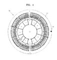
- FIG. 1 is a plan view of a related art microfluidic device, which is disclosed in U.S. Patent No. 6,992,278 .
- a mark 15 is made on a circumference of a platform 11 of the related art microfluidic device 10 to mark a home position.
- the mark 15 By emitting light onto the mark 15 to detect reflected light and setting the mark 15 as the home position, relative positions of valves, functional units and chambers can be determined.
- the mark 15 should be formed to have a relatively large size in order to reduce detection errors for the home position.
- determination error for the home position may be increased during emitting and reflecting light.
- the present invention provides a centrifugal force based microfluidic device that is improved to increase the precision of the determining of a home position, a microfluidic system including the microfluidic device and a method of determining a home position of the microfluidic device using the microfluidic system.
- a centrifugal force based microfluidic system including: a microfluidic device comprising a rotatable platform and an optical path formed to extend horizontally in a straight line from a circumference side of the platform; a motor rotating so as to control the microfluidic device; a light emitting unit emitting light towards the microfluidic device; a light receiving unit detecting the light emitted from the light emitting unit; and a controller determining a home position to be the position of the microfluidic device at the time when the light emitted from the light emitting unit is detected by the light receiving unit, wherein the light emitted from the light emitting unit passes through the optical path to be incident on the light receiving unit only when the microfluidic device is located in a predetermined position.
- the groove may be formed from an upper or lower surface of the platform.
- the optical path may be formed to cross the platform from one side of the circumference of the platform to another side of the circumference of the platform, and the platform may be disposed between the light emitting unit and the light receiving unit so that the light emitted from the light emitting unit passes through the optical path to be incident on the light receiving unit.
- a motor mounting hole, in which the motor is mounted, may be formed in the center of the platform, the optical path is formed to extend in a straight line through the motor mounting hole, and a through hole may be s formed in the motor so that the optical path is not blocked.
- a motor mounting hole, in which the motor is mounted, may be formed in the center of the platform, the optical path is formed to extend from one side of the circumference of the platform to the motor mounting hole, the motor may include a reflective surface reflecting light that is emitted by the light emitting unit to be incident on the motor along the optical path, and the light receiving unit may be disposed on the one same side, on which the light emitting unit is formed, so as to detect the light reflected by the reflective surface.
- the system may further include a half mirror passing the light emitted by the light emitting unit and reflecting the light reflected by the reflective surface of the motor towards the light receiving unit.
- the light receiving unit may include a light emitting diode (LED) or a laser diode (LD).
- LED light emitting diode
- LD laser diode
- a method of determining a home position of a microfluidic device including: rotating the microfluidic device including a rotatable platform and an optical path formed to extend horizontally in a straight line from the circumference of the platform; emitting light towards the microfluidic device by using a light emitting unit; and determining the home position to be the position of the microfluidic device at the point of time when the emitted light passes through the optical path to be detected in a light receiving unit.
- the optical path may be formed to cross the platform from one side of the circumference of the platform to another side of the circumference of the platform, and the light emitted from the light emitting unit in the emitting of light may pass through the optical path in the determining of the home position to be incident on the light receiving unit facing the light emitting unit, wherein the platform may be disposed between the light emitting unit and the light receiving unit.
- a motor mounting hole in which a motor comprising a through hole formed therein is mounted to rotate so as to control the microfluidic device, may be formed in the center of the platform, the optical path is formed to extend in a straight line through the motor mounting hole, and the light emitted from the light emitting unit in the emitting of the light may be incident on the light receiving unit through the through hole in the determining of the home position.
- a motor mounting hole in which a motor comprising a reflective surface is mounted to rotate so as to control the microfluidic device, may be formed in the center of the platform, the optical path may be formed to extend from one side of the circumference of the platform to the motor mounting hole, and the light emitted from the light emitting unit in the emitting of the light may be reflected by the reflective surface of the motor along the optical path in the determining of the position to be incident on the light receiving unit disposed on the same side on which the light emitting unit is formed.
- the light reflected by the reflective surface of the motor in the determining of the position may be further reflected by a half mirror to be emitted towards the light receiving unit.
- FIG. 1 is a plan view of a related art microfluidic device
- FIG. 2 is a perspective view of a microfluidic system according to an exemplary embodiment of the present invention
- FIG. 3 is a perspective view of a microfluidic device illustrated in FIG. 2 , which is viewed from below, according to an exemplary embodiment of the present invention
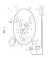
- FIG. 4 is a perspective view of a microfluidic system according to another exemplary embodiment of the present invention.
- FIG. 5 is a perspective view of a microfluidic device illustrated in FIG. 4 , which is viewed from below, according to an exemplary embodiment of the present invention.
- FIG. 2 is a perspective view of a microfluidic system 100 according to an exemplary embodiment of the present invention.
- FIG. 3 is a perspective view of a microfluidic device 101 illustrated in FIG. 2 , which is viewed from below.
- the microfluidic system 100 includes a microfluidic device 101 including a rotatable disk-type platform 102, a spindle motor 125 that is a kind of motor rotating so as to control the microfluidic device 101, and a light emitting unit 130, a light receiving unit 133 and a controller 135 for determining a home position of the microfluidic device 101.
- the microfluidic device 101 includes a chamber keeping a small quantity of a predetermined fluid on the platform 102, a channel along which a fluid flows, a valve regulating the flow of a fluid or various functional units receiving a fluid to perform predetermined functions.
- the microfluidic device 101 illustrated in FIG. 2 is a microfluidic device designed to perform an immunoassay and detect a result thereof, and includes a sample chamber 111, a bead chamber 112, a mix chamber 114, a buffer chamber 113, a waist chamber 116 and a reaction chamber 115.
- the sample chamber 111 is a place housing a sample such as a serum.
- the bead chamber 112 is a place housing beads mixed with the sample.
- the mix chamber 114 is a place to house a predetermined detection probe combined with the beads after capturing predetermined protein. In the mix chamber 114, the sample, the beads and the detection probe are mixed.
- the buffer chamber 113 is a place housing a buffer that dilutes and rinses a mixing solution of the sample, the beads and the detection probe, and discharges residue.
- the waist chamber 116 is a place housing the discharged residue.
- the reaction chamber 115 is a place housing predetermined substrate and enzyme reacting with the detection probe that is attached to the beads and moved together with the beads. The detection probe and the substrate react with each other to realize an optical signal.
- the microfluidic system 100 further includes a reaction detector 137 for detecting the optical signal due to the reaction.
- the sample chamber 111, the bead chamber 112 and the buffer chamber 113 are connected to the mix chamber 114.
- Valves 117, 118 and 119 controlling the flow of the fluid are arranged in each of channels.
- the valves 117, 118 and 119 usually close the channel, but open the channels under a predetermined condition. These valves may be called normally closed valves.
- the microfluidic system 100 further includes an external energy source 138 for providing energy to the valves 117, 118 and 119.
- the external energy source 138 may be a laser light source emitting a laser beam.
- the microfluidic device 101 includes an optical path 105 extending horizontally along in a straight line from a circumference side of the platform 102 through the center of the microfluidic device 101 and to the other side of the microfluidic device 101.
- the optical path 105 is a groove formed on a lower surface of the platform 102.
- the optical path 105 is illustrated to be a curved groove in FIGS. 2 and 3 , the present invention is not limited thereto. That is, an optical path may be a hole.
- an optical path may be a groove formed not on a lower surface of a platform but on an upper surface of the platform.
- the optical path 105 is formed to cross the platform 102 from one side of the platform 102 to other side of the platform 102.
- a spindle motor mounting hole 103 in which a spindle motor 125 is mounted, is disposed in the center of the optical path 105.
- a through hole 127 is formed in the spindle motor 125 so that the optical path 105 extending in an imaginary straight line may not be blocked by the spindle motor 125 mounted in the spindle motor mounting hole 103.
- the light emitting unit 130 emits light in a horizontal direction towards the rotating microfluidic device 101, and may include a light emitting diode (LED) emitting a visible ray or a laser diode (LD) emitting a laser beam.
- LED light emitting diode
- LD laser diode
- an emission direction of light emitted from the light emitting unit 130 coincides with an extending direction of the optical path 105 included in the platform 102. Accordingly, only at this time, the light emitted from the light emitting unit 130 can pass through the platform 102 along the optical path 105, and the position of the microfluidic device 101 at this time can be determined as the home position. The longer the optical path 105 is and the narrower the groove is, the higher the precision of determining the home position is.
- the light receiving unit 133 detects the light that is emitted from the light emitting unit 130 to pass through the platform 102, and may include a photodiode detecting incident light using photovoltaic effect.
- the light receiving unit 133 faces the light emitting unit 130, wherein the platform 102 is disposed between the light receiving unit 133 and the light emitting unit 130.
- the controller 135 may be a computer (not shown) connected to communicate with the light emitting unit 130, the light receiving unit 133, the reaction detector 137 and the external energy source 138.
- the controller 135 determines the home position to be the position of the microfluidic device 101 at the time when the light emitted from the light emitting unit 130 is detected as being incident on the light receiving unit 133.
- the microfluidic device 101 is equipped with the spindle motor 125.
- the spindle motor 125 is driven to be rotated.
- the through hole 127 of the spindle motor 125 and the optical path 105 are aligned so that the optical path 105 of the microfluidic device 101 may not be blocked by the spindle motor 125.
- light is emitted towards the rotating microfluidic device 101 using the light emitting unit 130.
- the position of the microfluidic device 101 at this time is determined to be the home position.
- the controller 135 Since the controller 135 stores information on a relative position of the reaction chamber 115, in which reaction needs to be detected, and information on relative positions of the valves 117, 118 and 119, to which energy needs to be provided, in the microfluidic device 101, the controller 135 determines the home position as described above to appropriately control the spindle motor 125 to rotate the microfluidic device 101 by an angle corresponding to the relative position of the reaction chamber 115 or the relative positions of the valves 117, 118 and 119, and thus the reaction chamber 115 can be aligned below the reaction detector 137, or one of the valves 117, 118 and 119 can be aligned below the external energy source 138.
- FIG. 4 is a perspective view of a microfluidic system 200 according to another exemplary embodiment of the present invention.
- FIG. 5 is a perspective view of a microfluidic device 201 illustrated in FIG. 4 , which is viewed from below.
- the microfluidic system 200 includes a microfluidic device 201 including a disk-type platform 202, a spindle motor 225 rotating the microfluidic device 201, and a light emitting unit 230, a light receiving unit 233 and a controller 235 for determining a home position of the microfluidic device 101.
- the microfluidic device 201 includes a chamber keeping a small quantity of a predetermined fluid on the platform 202, a channel along which a fluid flows, a valve regulating the flow of a fluid or various functional units receiving a fluid to perform predetermined functions. That is, the microfluidic device 201 illustrated in FIG. 4 is a microfluidic device designed to perform an immunoassay and detect a result thereof, similarly to the microfluidic device 100 illustrated in FIG. 2 , and includes a sample chamber 211, a bead chamber 212, a mix chamber 214, a buffer chamber 213, a waist chamber 216, a reaction chamber 215 and valves 217, 218 and 219 controlling the flow of a fluid.
- the microfluidic system 200 further includes a reaction detector 237 detecting an optical signal due to the immunoassay and an external energy source 238 providing energy to the valves 217, 218 and 219.
- the external energy source 238 may be a laser light source irradiating a laser beam.
- the microfluidic device 201 includes an optical path 205 extending horizontally in a straight line from a circumference side of the platform 202.
- the optical path 205 is a groove formed on a lower surface of the platform 202.
- the optical path 205 is illustrated to be a groove in FIGS. 4 and 5 , the present invention is not limited thereto. That is, the optical path may be a hole.
- a spindle motor mounting hole 203 in which a spindle motor 225 is mounted, is disposed in the center of the platform 202.
- the optical path 205 is formed to extend from one circumference side of the platform 202 to the spindle motor mounting hole 203.
- the spindle motor 225 mounted in the spindle motor mounting hole 203 includes a reflective surface 227 reflecting light incident on the spindle motor 225 along the optical path 205.
- the reflective surface 227 may be formed using a method in which all of or a part of the circumference side of the spindle motor 225 is coated with a metal capable of reflecting light.
- the light emitting unit 230 emits light in a horizontal direction towards the rotating microfluidic device 201, and may include an LED emitting a visible ray or a laser diode (LD) emitting a laser beam.
- an emission direction of light emitted from the light emitting unit 230 coincides with an extending direction of the optical path 205 included in the platform 202. Accordingly, only at this time, the light emitted from the light emitting unit 230 can be incident on the reflective surface 227 of the spindle motor 225 along the optical path 205, and can be reflected by the reflective surface 227.
- the position of the microfluidic device 201 at this time can be determined as the home position. The longer the optical path 205 is and the narrower the groove is, the higher the precision of determining the home position is.
- the light receiving unit 233 detects the light that is reflected on the reflective surface 227 and proceeds toward the circumference side of the platform 202 along the optical path 205.
- the light receiving unit 233 is disposed on the same side on which the light emitting unit 230 is located.
- the light receiving unit 233 may include a photodiode detecting incident light using photovoltaic effect.
- the microfluidic system 200 includes a half mirror 232 disposed between the light emitting unit 230 and the platform 202.
- the half mirror 232 passes light emitted towards the microfluidic device 201 from the light emitting unit 230, and reflects light, which is reflected on the reflective surface 227 and proceeds toward the circumference side of the platform 202, toward the light receiving unit 233.
- the controller 235 may be a computer (not shown) connected to communicate with the light emitting unit 230, the light receiving unit 233, the reaction detector 237 and the external energy source 238.
- the controller 235 determines the home position to be the position of the microfluidic device 201 at the time when the light emitted from the light emitting unit 230 is detected as being incident on the light receiving unit 233.
- the microfluidic device 201 is equipped with the spindle motor 225.
- the spindle motor 225 is driven to be rotated.
- the microfluidic device 201 is aligned so that the reflective surface 227 of the spindle motor 225 may face an end of the spindle motor mounting hole 203 of the optical path 205.
- light is emitted towards the rotating microfluidic device 201 using the light emitting unit 230.
- the position of the microfluidic device 201 is determined as the home position.
- the controller 235 Since the controller 235 stores information on a relative position of the reaction chamber 215, in which a reaction is to be detected, and information on relative positions of the valves 217, 218 and 219, to which energy needs to be provided, in the fluidic device 201, the controller 235 determines the home position as described above to appropriately control the spindle motor 225 to rotate the microfluidic device 201 by an angle corresponding to the relative position of the reaction chamber 215 or the relative positions of the valves 217, 218 and 219, and thus the reaction chamber 215 can be aligned below the reaction detector 237, or the valves 217, 218 and 219 can be aligned below the external energy source 238.
- the precision of determining the home position can be increased with respect to the related art.
- the precision of determining the home position can be further increased as the optical path is longer and narrower.
Landscapes
- Chemical & Material Sciences (AREA)
- Health & Medical Sciences (AREA)
- Physics & Mathematics (AREA)
- Analytical Chemistry (AREA)
- General Health & Medical Sciences (AREA)
- Life Sciences & Earth Sciences (AREA)
- Biochemistry (AREA)
- General Physics & Mathematics (AREA)
- Immunology (AREA)
- Pathology (AREA)
- Dispersion Chemistry (AREA)
- Hematology (AREA)
- Clinical Laboratory Science (AREA)
- Chemical Kinetics & Catalysis (AREA)
- Engineering & Computer Science (AREA)
- Mathematical Physics (AREA)
- Theoretical Computer Science (AREA)
- Spectroscopy & Molecular Physics (AREA)
- Automatic Analysis And Handling Materials Therefor (AREA)
- Centrifugal Separators (AREA)
Applications Claiming Priority (1)
| Application Number | Priority Date | Filing Date | Title |
|---|---|---|---|
| KR1020070037164A KR101278154B1 (ko) | 2007-04-16 | 2007-04-16 | 원심력 기반의 미세유동 장치, 이를 구비한 미세유동시스템 및, 상기 미세유동 장치의 홈 위치 결정 방법 |
Publications (2)
| Publication Number | Publication Date |
|---|---|
| EP1983347A2 true EP1983347A2 (fr) | 2008-10-22 |
| EP1983347A3 EP1983347A3 (fr) | 2009-06-24 |
Family
ID=39539622
Family Applications (1)
| Application Number | Title | Priority Date | Filing Date |
|---|---|---|---|
| EP07121889A Withdrawn EP1983347A3 (fr) | 2007-04-16 | 2007-11-29 | Dispositif microfluidique à force centrifuge, système microfluidique l'incorporant, et procédé pour déterminer la position d'accueil du dispositif microfluidique |
Country Status (3)
| Country | Link |
|---|---|
| US (1) | US7758810B2 (fr) |
| EP (1) | EP1983347A3 (fr) |
| KR (1) | KR101278154B1 (fr) |
Cited By (4)
| Publication number | Priority date | Publication date | Assignee | Title |
|---|---|---|---|---|
| EP2214023A1 (fr) * | 2009-01-15 | 2010-08-04 | Samsung Electronics Co., Ltd. | Appareil et procédé pour reconnaître la position initiale d'un corps rotatif |
| EP2311565A1 (fr) | 2009-10-14 | 2011-04-20 | F. Hoffmann-La Roche AG | Composition de lubrification |
| CN102099688A (zh) * | 2009-03-12 | 2011-06-15 | 松下电器产业株式会社 | 分析用仪器 |
| WO2014058757A3 (fr) * | 2012-10-08 | 2014-08-07 | General Electric Company | Plate-forme microfluidique centripétale permettant de tester des substances réactives au test lal |
Families Citing this family (32)
| Publication number | Priority date | Publication date | Assignee | Title |
|---|---|---|---|---|
| US8988881B2 (en) | 2007-12-18 | 2015-03-24 | Sandia Corporation | Heat exchanger device and method for heat removal or transfer |
| US9005417B1 (en) | 2008-10-01 | 2015-04-14 | Sandia Corporation | Devices, systems, and methods for microscale isoelectric fractionation |
| EP2952906A1 (fr) | 2009-08-07 | 2015-12-09 | F. Hoffmann-La Roche AG | Système d'analyse d'échantillons liquides |
| EP2311563A1 (fr) | 2009-08-07 | 2011-04-20 | F. Hoffmann-La Roche AG | Unités de traitement et procédé pour le traitement d'échantillons liquides |
| WO2011042426A1 (fr) | 2009-10-05 | 2011-04-14 | Alphahelix Molecular Diagnostics Ab (Publ) | Rotor multifonctionnel |
| US9186668B1 (en) | 2010-06-04 | 2015-11-17 | Sandia Corporation | Microfluidic devices, systems, and methods for quantifying particles using centrifugal force |
| US8945914B1 (en) | 2010-07-08 | 2015-02-03 | Sandia Corporation | Devices, systems, and methods for conducting sandwich assays using sedimentation |
| US9795961B1 (en) | 2010-07-08 | 2017-10-24 | National Technology & Engineering Solutions Of Sandia, Llc | Devices, systems, and methods for detecting nucleic acids using sedimentation |
| US8962346B2 (en) | 2010-07-08 | 2015-02-24 | Sandia Corporation | Devices, systems, and methods for conducting assays with improved sensitivity using sedimentation |
| US9261100B2 (en) | 2010-08-13 | 2016-02-16 | Sandia Corporation | Axial flow heat exchanger devices and methods for heat transfer using axial flow devices |
| CN102441356B (zh) * | 2010-10-12 | 2013-08-21 | 扬博科技股份有限公司 | 离心式微流体装置 |
| TWI411779B (zh) * | 2011-05-18 | 2013-10-11 | Univ Nat Sun Yat Sen | 微流體生物晶片及其自動化反應偵測系統 |
| US9244065B1 (en) | 2012-03-16 | 2016-01-26 | Sandia Corporation | Systems, devices, and methods for agglutination assays using sedimentation |
| TWD157676S (zh) * | 2012-06-01 | 2013-12-01 | 三星電子股份有限公司 | 體液檢查盤的底盤之部分 |
| TWD161734S (zh) * | 2012-06-01 | 2014-07-11 | 三星電子股份有限公司 | 體液檢查盤 |
| US9903001B1 (en) | 2012-07-19 | 2018-02-27 | National Technology & Engineering Solutions Of Sandia, Llc | Quantitative detection of pathogens in centrifugal microfluidic disks |
| US10197480B2 (en) | 2012-11-07 | 2019-02-05 | Sandstone Diagnostics, Inc. | Methods and devices for processing samples and counting cells |
| CA2885845C (fr) | 2012-11-07 | 2019-10-29 | Sandstone Diagnostics, Inc. | Procedes et dispositifs de traitement d'echantillons et de numeration de cellules |
| TWI477321B (zh) * | 2012-12-28 | 2015-03-21 | Ind Tech Res Inst | 微流體混合裝置及其方法 |
| US9304128B1 (en) | 2013-02-01 | 2016-04-05 | Sandia Corporation | Toxin activity assays, devices, methods and systems therefor |
| WO2014124179A1 (fr) | 2013-02-07 | 2014-08-14 | Sandstone Diagnostics, Inc. | Traitement d'échantillons, répartition de fluides et dosage à sédimentation automatisés |
| US9500579B1 (en) | 2013-05-01 | 2016-11-22 | Sandia Corporation | System and method for detecting components of a mixture including tooth elements for alignment |
| CN104657400B (zh) * | 2013-11-19 | 2018-02-02 | 光宝科技股份有限公司 | 离心分析系统以及其分析方法 |
| US9803238B1 (en) | 2013-11-26 | 2017-10-31 | National Technology & Engineering Solutions Of Sandia, Llc | Method and apparatus for purifying nucleic acids and performing polymerase chain reaction assays using an immiscible fluid |
| JP6087272B2 (ja) * | 2013-12-20 | 2017-03-01 | 信越ポリマー株式会社 | 分析基板 |
| US9702871B1 (en) | 2014-11-18 | 2017-07-11 | National Technology & Engineering Solutions Of Sandia, Llc | System and method for detecting components of a mixture including a valving scheme for competition assays |
| US10254298B1 (en) | 2015-03-25 | 2019-04-09 | National Technology & Engineering Solutions Of Sandia, Llc | Detection of metabolites for controlled substances |
| US10981174B1 (en) | 2016-08-04 | 2021-04-20 | National Technology & Engineering Solutions Of Sandia, Llc | Protein and nucleic acid detection for microfluidic devices |
| US10406528B1 (en) | 2016-08-04 | 2019-09-10 | National Technology & Engineering Solutions Of Sandia, Llc | Non-contact temperature control system for microfluidic devices |
| US10786811B1 (en) | 2016-10-24 | 2020-09-29 | National Technology & Engineering Solutions Of Sandia, Llc | Detection of active and latent infections with microfluidic devices and systems thereof |
| US20200129983A1 (en) * | 2018-10-29 | 2020-04-30 | Tokitae Llc | Systems for the control of valveless microfluidic devices using rotational and pistoning motion |
| CA3119623A1 (fr) * | 2018-11-13 | 2020-05-22 | National Research Council Of Canada | Interface automatisee monde/puce pour plateformes microfluidiques centrifuges |
Citations (3)
| Publication number | Priority date | Publication date | Assignee | Title |
|---|---|---|---|---|
| WO2000079285A2 (fr) * | 1999-06-18 | 2000-12-28 | Gamera Bioscience Corporation | Dispositifs et methodes permettant d"effectuer des analyses homogenes miniature |
| WO2002010448A2 (fr) * | 2000-08-01 | 2002-02-07 | Trace Biotech Ag | Moyens et procedes pour effectuer des bioanalyses chimiques et biologiques |
| US6992278B2 (en) | 2002-04-08 | 2006-01-31 | Gyros Ab | Homing process |
Family Cites Families (7)
| Publication number | Priority date | Publication date | Assignee | Title |
|---|---|---|---|---|
| JPH0861934A (ja) * | 1994-08-18 | 1996-03-08 | Oki Electric Ind Co Ltd | 回転体の位置検出装置 |
| GB9418981D0 (en) | 1994-09-21 | 1994-11-09 | Univ Glasgow | Apparatus and method for carrying out analysis of samples |
| GB2293876A (en) | 1994-10-05 | 1996-04-10 | Motorola Semiconducteurs | Rotation sensor |
| AU702403B2 (en) * | 1995-12-05 | 1999-02-18 | Gamera Bioscience | Devices and methods for using centripetal acceleration to drive fluid movement in a microfluidics system with on-board informatics |
| EP1004015B1 (fr) | 1997-08-15 | 2004-01-02 | Alexion Pharmaceuticals, Inc. | Dispositif permettant de realiser des dosages au niveau de sites reactionnels |
| SE0104077D0 (sv) | 2001-10-21 | 2001-12-05 | Gyros Ab | A method and instrumentation for micro dispensation of droplets |
| KR100601964B1 (ko) | 2004-09-07 | 2006-07-19 | 삼성전자주식회사 | 다채널 다중 컬러 측정을 위한 광검출장치 및 이를 채용한다채널 시료 분석기 |
-
2007
- 2007-04-16 KR KR1020070037164A patent/KR101278154B1/ko not_active Expired - Fee Related
- 2007-10-22 US US11/875,973 patent/US7758810B2/en not_active Expired - Fee Related
- 2007-11-29 EP EP07121889A patent/EP1983347A3/fr not_active Withdrawn
Patent Citations (3)
| Publication number | Priority date | Publication date | Assignee | Title |
|---|---|---|---|---|
| WO2000079285A2 (fr) * | 1999-06-18 | 2000-12-28 | Gamera Bioscience Corporation | Dispositifs et methodes permettant d"effectuer des analyses homogenes miniature |
| WO2002010448A2 (fr) * | 2000-08-01 | 2002-02-07 | Trace Biotech Ag | Moyens et procedes pour effectuer des bioanalyses chimiques et biologiques |
| US6992278B2 (en) | 2002-04-08 | 2006-01-31 | Gyros Ab | Homing process |
Cited By (14)
| Publication number | Priority date | Publication date | Assignee | Title |
|---|---|---|---|---|
| EP2214023A1 (fr) * | 2009-01-15 | 2010-08-04 | Samsung Electronics Co., Ltd. | Appareil et procédé pour reconnaître la position initiale d'un corps rotatif |
| US8218136B2 (en) | 2009-01-15 | 2012-07-10 | Samsung Electronics Co., Ltd. | Apparatus and method for recognizing home position of rotatable body |
| CN102099688A (zh) * | 2009-03-12 | 2011-06-15 | 松下电器产业株式会社 | 分析用仪器 |
| CN102099688B (zh) * | 2009-03-12 | 2013-08-28 | 松下电器产业株式会社 | 分析用仪器 |
| EP2311565A1 (fr) | 2009-10-14 | 2011-04-20 | F. Hoffmann-La Roche AG | Composition de lubrification |
| US8580567B2 (en) | 2009-10-14 | 2013-11-12 | Roche Diagnostics Operations, Inc. | Method for the automated analysis of liquid samples using centrifugal force in a microfluidic structure |
| WO2014058757A3 (fr) * | 2012-10-08 | 2014-08-07 | General Electric Company | Plate-forme microfluidique centripétale permettant de tester des substances réactives au test lal |
| US9678079B2 (en) | 2012-10-08 | 2017-06-13 | General Electric Company | Microfluidic LAL-reactive substances testing method and apparatus |
| US9880166B2 (en) | 2012-10-08 | 2018-01-30 | General Electric Company | Sensitive and rapid method for detection of low levels of LAL-reactive substances |
| US10082505B2 (en) | 2012-10-08 | 2018-09-25 | General Electric Company | Centripetal microfluidic platform for LAL-reactive substances testing |
| US10302642B2 (en) | 2012-10-08 | 2019-05-28 | General Electric Company | Sensitive and rapid method for detection of low levels of LAL-reactive substances |
| US10352934B2 (en) | 2012-10-08 | 2019-07-16 | General Electric Company | Preloaded test substrates for testing LAL-reactive substances, methods of use, and methods of making |
| US10451622B2 (en) | 2012-10-08 | 2019-10-22 | Bl Technologies, Inc. | Centripetal microfluidic platform for LAL reactive substances testing |
| US11422133B2 (en) | 2012-10-08 | 2022-08-23 | Bl Technologies, Inc. | Centripetal microfluidic platform for LAL reactive substances testing |
Also Published As
| Publication number | Publication date |
|---|---|
| EP1983347A3 (fr) | 2009-06-24 |
| US20080252905A1 (en) | 2008-10-16 |
| KR101278154B1 (ko) | 2013-06-27 |
| US7758810B2 (en) | 2010-07-20 |
| KR20080093341A (ko) | 2008-10-21 |
Similar Documents
| Publication | Publication Date | Title |
|---|---|---|
| US7758810B2 (en) | Centrifugal force based microfluidic device, microfluidic system including the same, and method of determining home position of the microfluidic device | |
| US8242433B2 (en) | Centrifugal force based platform, microfluidic system including the same, and method of determining home position of the platform | |
| JP4423189B2 (ja) | 表面プラズモン共鳴に基づく検出装置 | |
| EP1462805B1 (fr) | Dispositif de mesure d'echantillons | |
| US20110017905A1 (en) | Microfluidic device, microfluidic system including the same, and method for detecting reference angle of the microfluidic device | |
| US9101935B2 (en) | Microfluidic apparatus and control method thereof | |
| EP2684606B1 (fr) | Dispositif d'essai et procédé de contrôle de celui-ci | |
| US20150093771A1 (en) | Microfluidic analytical device for analysis of chemical or biological samples, method and system thereof | |
| US20090021741A1 (en) | Optical detection apparatus, optical detection method, and microfluidic system including the optical detection apparatus | |
| JP4980452B2 (ja) | 分析用具、分析用具における反応槽の特定方法および分析装置 | |
| US20100086441A1 (en) | Beam radiating device, bio-chemical analyzer including the beam radiating device, and bio-chemical analyzing system including the bio-chemical analyzer | |
| KR101338930B1 (ko) | 광학 검출기 시험 장치 | |
| JP5174627B2 (ja) | 分析装置 | |
| EP2685236B1 (fr) | Disposition et son procédé de contrôle | |
| JP2011080769A (ja) | 円盤型分析チップおよびそれを用いた測定システム | |
| US12066450B2 (en) | Substrate for sample analysis | |
| JP4444094B2 (ja) | 流路と、この流路を用いた液体計量装置と、この液体計量装置を用いた液体分析装置と、その液体計量方法 | |
| EP2976619A1 (fr) | Lampe et obturateur destinés à un analyseur d'échantillons | |
| CN102636636A (zh) | 盘型微流器件 | |
| CN222671824U (zh) | 光路模块及生化分析仪 | |
| JP2010019761A (ja) | 分析装置 | |
| JP2006145452A (ja) | 検液用チャンバーと、この検液用チャンバーを用いた液体分析装置と、前記検液用チャンバーの厚み測定方法 | |
| JP2020006343A (ja) | 流体取扱装置および流体取扱システム | |
| JP2009109199A (ja) | 位置決め装置及びそれを用いた分析装置 | |
| JP2010122021A (ja) | 分析装置 |
Legal Events
| Date | Code | Title | Description |
|---|---|---|---|
| PUAI | Public reference made under article 153(3) epc to a published international application that has entered the european phase |
Free format text: ORIGINAL CODE: 0009012 |
|
| AK | Designated contracting states |
Kind code of ref document: A2 Designated state(s): AT BE BG CH CY CZ DE DK EE ES FI FR GB GR HU IE IS IT LI LT LU LV MC MT NL PL PT RO SE SI SK TR |
|
| AX | Request for extension of the european patent |
Extension state: AL BA HR MK RS |
|
| PUAL | Search report despatched |
Free format text: ORIGINAL CODE: 0009013 |
|
| AK | Designated contracting states |
Kind code of ref document: A3 Designated state(s): AT BE BG CH CY CZ DE DK EE ES FI FR GB GR HU IE IS IT LI LT LU LV MC MT NL PL PT RO SE SI SK TR |
|
| AX | Request for extension of the european patent |
Extension state: AL BA HR MK RS |
|
| 17P | Request for examination filed |
Effective date: 20091215 |
|
| 17Q | First examination report despatched |
Effective date: 20100119 |
|
| AKX | Designation fees paid |
Designated state(s): DE FR GB SE |
|
| RAP1 | Party data changed (applicant data changed or rights of an application transferred) |
Owner name: SAMSUNG ELECTRONICS CO., LTD. |
|
| STAA | Information on the status of an ep patent application or granted ep patent |
Free format text: STATUS: THE APPLICATION IS DEEMED TO BE WITHDRAWN |
|
| 18D | Application deemed to be withdrawn |
Effective date: 20150414 |