EP1984181B1 - Formzylinderankopplung - Google Patents
Formzylinderankopplung Download PDFInfo
- Publication number
- EP1984181B1 EP1984181B1 EP07703344.7A EP07703344A EP1984181B1 EP 1984181 B1 EP1984181 B1 EP 1984181B1 EP 07703344 A EP07703344 A EP 07703344A EP 1984181 B1 EP1984181 B1 EP 1984181B1
- Authority
- EP
- European Patent Office
- Prior art keywords
- piece
- cylinder
- counter
- group according
- printing group
- Prior art date
- Legal status (The legal status is an assumption and is not a legal conclusion. Google has not performed a legal analysis and makes no representation as to the accuracy of the status listed.)
- Not-in-force
Links
- 238000007639 printing Methods 0.000 title claims description 42
- 230000008878 coupling Effects 0.000 title description 11
- 238000010168 coupling process Methods 0.000 title description 11
- 238000005859 coupling reaction Methods 0.000 title description 11
- 238000006073 displacement reaction Methods 0.000 claims description 13
- 230000005540 biological transmission Effects 0.000 claims description 7
- 238000000034 method Methods 0.000 claims description 3
- 230000000295 complement effect Effects 0.000 claims description 2
- 238000004140 cleaning Methods 0.000 description 1
- 230000007423 decrease Effects 0.000 description 1
- 238000009826 distribution Methods 0.000 description 1
- 238000007646 gravure printing Methods 0.000 description 1
- 238000004519 manufacturing process Methods 0.000 description 1
- 238000002360 preparation method Methods 0.000 description 1
- 125000006850 spacer group Chemical group 0.000 description 1
- 230000003068 static effect Effects 0.000 description 1
Images


Classifications
-
- B—PERFORMING OPERATIONS; TRANSPORTING
- B41—PRINTING; LINING MACHINES; TYPEWRITERS; STAMPS
- B41F—PRINTING MACHINES OR PRESSES
- B41F13/00—Common details of rotary presses or machines
- B41F13/008—Mechanical features of drives, e.g. gears, clutches
-
- F—MECHANICAL ENGINEERING; LIGHTING; HEATING; WEAPONS; BLASTING
- F16—ENGINEERING ELEMENTS AND UNITS; GENERAL MEASURES FOR PRODUCING AND MAINTAINING EFFECTIVE FUNCTIONING OF MACHINES OR INSTALLATIONS; THERMAL INSULATION IN GENERAL
- F16D—COUPLINGS FOR TRANSMITTING ROTATION; CLUTCHES; BRAKES
- F16D1/00—Couplings for rigidly connecting two coaxial shafts or other movable machine elements
- F16D1/06—Couplings for rigidly connecting two coaxial shafts or other movable machine elements for attachment of a member on a shaft or on a shaft-end
- F16D1/08—Couplings for rigidly connecting two coaxial shafts or other movable machine elements for attachment of a member on a shaft or on a shaft-end with clamping hub; with hub and longitudinal key
- F16D1/09—Couplings for rigidly connecting two coaxial shafts or other movable machine elements for attachment of a member on a shaft or on a shaft-end with clamping hub; with hub and longitudinal key with radial clamping due to axial loading of at least one pair of conical surfaces
- F16D1/093—Couplings for rigidly connecting two coaxial shafts or other movable machine elements for attachment of a member on a shaft or on a shaft-end with clamping hub; with hub and longitudinal key with radial clamping due to axial loading of at least one pair of conical surfaces using one or more elastic segmented conical rings forming at least one of the conical surfaces, the rings being expanded or contracted to effect clamping
- F16D1/095—Couplings for rigidly connecting two coaxial shafts or other movable machine elements for attachment of a member on a shaft or on a shaft-end with clamping hub; with hub and longitudinal key with radial clamping due to axial loading of at least one pair of conical surfaces using one or more elastic segmented conical rings forming at least one of the conical surfaces, the rings being expanded or contracted to effect clamping with clamping effected by ring contraction only
- F16D1/096—Couplings for rigidly connecting two coaxial shafts or other movable machine elements for attachment of a member on a shaft or on a shaft-end with clamping hub; with hub and longitudinal key with radial clamping due to axial loading of at least one pair of conical surfaces using one or more elastic segmented conical rings forming at least one of the conical surfaces, the rings being expanded or contracted to effect clamping with clamping effected by ring contraction only the ring or rings being located between the shaft and the hub
-
- B—PERFORMING OPERATIONS; TRANSPORTING
- B41—PRINTING; LINING MACHINES; TYPEWRITERS; STAMPS
- B41P—INDEXING SCHEME RELATING TO PRINTING, LINING MACHINES, TYPEWRITERS, AND TO STAMPS
- B41P2213/00—Arrangements for actuating or driving printing presses; Auxiliary devices or processes
- B41P2213/10—Constitutive elements of driving devices
- B41P2213/25—Couplings; Clutches
-
- F—MECHANICAL ENGINEERING; LIGHTING; HEATING; WEAPONS; BLASTING
- F16—ENGINEERING ELEMENTS AND UNITS; GENERAL MEASURES FOR PRODUCING AND MAINTAINING EFFECTIVE FUNCTIONING OF MACHINES OR INSTALLATIONS; THERMAL INSULATION IN GENERAL
- F16D—COUPLINGS FOR TRANSMITTING ROTATION; CLUTCHES; BRAKES
- F16D1/00—Couplings for rigidly connecting two coaxial shafts or other movable machine elements
- F16D1/06—Couplings for rigidly connecting two coaxial shafts or other movable machine elements for attachment of a member on a shaft or on a shaft-end
- F16D1/08—Couplings for rigidly connecting two coaxial shafts or other movable machine elements for attachment of a member on a shaft or on a shaft-end with clamping hub; with hub and longitudinal key
- F16D1/09—Couplings for rigidly connecting two coaxial shafts or other movable machine elements for attachment of a member on a shaft or on a shaft-end with clamping hub; with hub and longitudinal key with radial clamping due to axial loading of at least one pair of conical surfaces
- F16D2001/0903—Couplings for rigidly connecting two coaxial shafts or other movable machine elements for attachment of a member on a shaft or on a shaft-end with clamping hub; with hub and longitudinal key with radial clamping due to axial loading of at least one pair of conical surfaces the clamped shaft being hollow
Definitions
- the invention relates to a printing unit in a rotary printing press according to the preamble of patent claim 1 and a method according to the preamble of patent claim 15.
- a drive of such a printing unit may be a separate, associated with the cylinder drive motor, usually an electric motor, but also one of a multi-cylinder driving drive branching shaft. In the following, therefore, there will be talk of a drive shaft, which provides the torque required for the rotation of the cylinder.
- DE 103 53 634 A1 and the DE 103 29 429 A1 disclose drive connections between a drive member and the journal of a printing cylinder.
- the pamphlets DE 38 04 673 C1 . US 5,672,026 . GB 750 826 and DE 198 36 259 A1 all of which do not show a printing machine, disclose ways in which a non-rotatable drive connection can be made between a drive member and a pin, with inclined surfaces present, the relative displacement of which results in the distortion of a component on the pin. However, this shift occurs due to manual operation or hydraulic actuation.
- a cylinder can be non-rotatably connected via transmission means to a drive shaft, wherein the cylinder comprises a pin which is substantially rotationally symmetrical.
- Special components or measures for a positive connection are not provided or not to make, because the connection works on the basis of a frictional connection.
- the transmission means comprise at least one connecting piece and at least one counterpart, wherein at least one of these pieces, ie either the connecting piece or the counterpart or even all these pieces, comprises an inclined surface.
- the respective other piece comprises one or more edges or surfaces which are in contact with the oblique surface of the one piece.
- the invention comprises means for relative displacement of the connector and the counterpart. Due to the relative displacement, a force which increases or decreases depending on the direction of displacement is exerted on the connecting piece and the counterpart via the inclined surface. Depending on which of these pieces is more elastic, this piece will change in its dimensions. In rotationally symmetric pieces, therefore, the outer or the inner diameter will change.
- the counterpart and / or the sleeve on a recess into which a locking pin can engage is a slot extending in the axial direction, whereby on the one hand, the axial movement of the counterpart is made possible, but on the other hand, the locking pin for the purpose of the intervention must not be accurately positioned.
- a recess and an increase such as a stop against which the locking pin abuts when the sleeve is rotated relative to the locking pin.
- the locking pin does not have to be permanently loaded with a force, so that it slips into the blind hole.
- a stop avoids that with relatively fast rotation of the sleeve of the locking pin does not slip into the blind hole, but skips this. In this way, it is possible to use the angular momentum applied to the system to produce a stronger frictional connection between the connector and the counterpart.
- Both blind hole and stop include a wall against which the locking pin ultimately abuts to prevent the further rotation of the sleeve.
- a corresponding wall conceivable, such as a recess with a radially extending wall, wherein the recess comprises a slope on which the locking pin can slide. This would also ensure that the locking pin rests against the wall.
- the second of said pieces has a complementary to the first inclined surface inclined surface, whereby a better distribution of force achieved and thus increased wear or even the damage of the pieces is avoided.
- the connecting piece starting from its end facing the counterpart, comprises a blind hole comprising an oblique surface.
- This blind hole is thus characterized by an altered diameter with increasing depth. For manufacturing reasons, a reduced diameter with increasing depth is usually provided.
- the counterpart comprises an annular element which comprises an oblique surface on its outer surface, that is, for example, has a conical shape.
- the end of the counterpart with the smaller circumference facing the connecting piece so that the counterpart can be inserted into the blind hole of the connecting piece.
- the counterpart is divided in the circumferential direction into segments. This subdivision can be achieved in a simple manner by introducing incisions starting from the smaller diameter end of the counterpart. In this way, the counterpart increased elasticity is given, whereby the inner diameter can be reduced with less effort.
- it can also be provided in another embodiment of the invention to vary the inner or outer circumference of the connecting piece. In this case, the connector is to be divided into segments in the circumferential direction.
- a particularly preferred embodiment of the invention includes threads as a means for relative displacement of the connector and the counterpart.
- Each of the pieces involved is with a component with connected to a thread, so that by the rotation of both components to each other a shift takes place.
- the counterpart comprises a sleeve which has a thread on its inner circumference.
- This sleeve is held by spacers, for example, at a distance from the annular element and can be rotatably mounted relative thereto.
- the connector advantageously also has a thread on its outer surface.
- the connecting piece may also have an internal thread and the counterpart and / or the sleeve enclosing this may have an external thread.
- the relative displacement is achieved in a particularly simple manner.
- the locking pin is movable by means of a piston-cylinder unit. So if the locking pin to be introduced into the slot, the piston-cylinder unit with a pressure medium, such as compressed air, is applied, so that the locking pin is applied to the outer surface of the sleeve or the counterpart. By rotation of the recess having the piece of the locking pin is automatically introduced when the recess reaches the locking pin in the recess.
- a pressure medium such as compressed air
- the drive shaft is assigned its own drive motor.
- the coupling of the cylinder to the drive shaft can be independent of the rotation of other existing in the printing cylinder cylinder. It is particularly advantageous if the Rotary axis of the drive shaft and the axis of rotation of the rotor of the drive motor are substantially aligned with each other. However, since an alignment of these two axes of rotation can not always be ensured, it may be advantageous if a rotation-proof, but provided with a certain axial and radial clearance compensation element between the rotor and the drive shaft is provided. Such a compensating element may be a bellows. It is particularly noteworthy, however, that such a compensation element allows an axial displacement of the connecting piece relative to the motor, so that in an axial displacement of the connecting piece, the tracking of the motor is not necessary.
- the connecting piece is rotatably mounted.
- the bearing bearing the connector can in turn be supported on components of the machine frame. Due to the mounting of the connecting piece, it is possible to dispense with a bearing which supports the journal of the forme cylinder. In this way, the provision and / or the postponement of bearings on pins of cylinders form can be saved so that it can come on the one hand to a cost savings, on the other hand, a lesser amount of work is caused when replacing the forme cylinder.
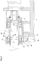
- Fig. 1 shows a view of a coupling device in a printing unit according to the invention, before a non-rotatable drive connection between cylinder 1, for example a pressure cylinder, and drive shaft 2 has been prepared.
- the Fig. 2 shows the same view after making the non-rotatable connection.
- the coupling device 3 is arranged on a console 4, which may be part of the printing press frame and / or may be displaceable relative to the printing press frame.
- a console 4 which may be part of the printing press frame and / or may be displaceable relative to the printing press frame.
- two supports 5, 6 are fixed, which carry a bush 7, the latter having a stop 8 at its end facing away from the cylinder 1.
- a connecting piece 11 is rotatably mounted.
- a ring 12 is fixed frontally, for example by means of a screw 13.
- the ring 12 is connected to a bellows 14, which produces a rotationally fixed connection to the connection socket 15.
- the connector 15 is in turn rotatably connected to the drive shaft 2.
- Connector 11 and drive shaft 2 can but also be connected in a different way. However, it is important that a non-rotatable connection is made.
- the drive shaft 2 is driven by its own drive motor 16, wherein the rotor of the motor, the drive shaft 2 directly, ie can drive without an interposition of gear stages.
- the drive shaft 2 can also be acted upon in other ways with a drive torque, for example, from a branch gear in the course of a vertical wave, which several cylinders or other components of a printing press together transmits the torque from a single drive.
- the drive shaft 2 facing away from the end of the connecting piece 11 has a blind hole 19, which has an inclined surface 18 at its beginning.
- This inclined surface 18 is rotationally symmetrical and tapers in the direction of the blind hole 19.
- the blind hole 19 serves to receive the pin 20 of the cylinder 1, wherein pin 20 and connector 11 do not touch.
- the connecting piece 11 since the connecting piece 11 carries at least a portion of the weight of the cylinder 1, as will be apparent below, the bearing 9, which rotatably supports the connecting piece 11, to dimension sufficiently.
- the pin 20 is enclosed by a counterpart 21 which is annular.
- This counterpart 21 has oblique surfaces 22 on its outer circumference, that is to say it has a conical shape, the end with the smaller outer circumference facing the connecting piece 11.
- the counterpart 21 includes an annular ridge 33.
- the groove 34 or the shoulder of a sleeve 24 runs.
- an intermediate ring 23 is detachably attached to this end, for example screwed.
- the sleeve 24 with an internal thread 25 which meshes with the introduced into the outer surface of the connecting piece 11 thread 26.
- a holder 27 About a holder 27 is a, preferably pneumatically actuated, piston-cylinder unit 28 fixed to the frame fixed to the support 5.
- a locking pin 29 Arranged on the push rod of the piston-cylinder unit 28 is a locking pin 29, which is displaceable in the-essentially-radial direction of the sleeve 24.
- a stop 35 In the sleeve 24 extending in the axial direction of the sleeve 24 extending in the axial direction of the sleeve 24 elongated hole 30 is introduced or a stop 35 is arranged, in or to which the locking pin 29 border or can be created. This situation is in Fig. 1 shown.
- the sleeve 24 can be taken immediately, so that after a certain angle of rotation of the locking pin 29 slips into the blind hole 30 or applies to the stop 35. In this way, the sleeve 24 is prevented from further rotating with the connecting piece 11. However, if the sleeve does not rotate with it, then the connecting piece 11 moves in the axial direction relative to the counterpart 21, so that by the frictional engagement occurring immediately, it continues to rotate together with the connecting piece 11, as a result of which the sleeve 24 is also set in rotation and again a certain angle of rotation of the locking pin 29 slips into the blind hole 30 and prevents further rotation of the sleeve 24. This situation is in Fig. 1 shown.
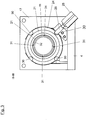
- Fig. 3 is the section III - III of the Fig. 1 shown. Same elements are with those from the Fig. 1 and 2 provided already known reference numerals. From this figure it can be seen that over the circumference of the sleeve 24 a plurality, in the example shown four, slots can be provided to keep the angle of rotation to lock small. Furthermore, the slots 31 can be seen, which are introduced into the provided with the inclined surface 22 part of the counterpart 21 in its axial direction to increase its compliance with force by the inclined surface 18 of the connecting piece 11.
- the printing unit according to the invention offers a way to change a cylinder quickly, easily and almost without manual intervention.
- the cylinder does not need to have any adapted elements. He only has to have a pin which is matched to the inner diameter of the counterpart 21.
- a compensating sleeve 32 may be used to match the diameters.
- Fig. 4 shows a further embodiment of the invention, wherein instead of the slots on the outer circumference of the sleeve 24, a stop 35 or more, advantageously two, stops are arranged.
- the piston-cylinder unit 28 moves the locking pin 29, the latter abuts against the outer surface of the sleeve 24, or there is a very small distance.
- the stop 35 abuts against the locking pin 29, so that a further rotation of the sleeve 24 is prevented.
- stopper 35 and locking pin 29 can be brought into contact even at a large relative speed, without a large amount of wear occurs.
- these are detachably arranged on the sleeve or the piston-cylinder unit.
- the locking pin is retracted so that the stop can pass under the locking pin in the printing operation. If connector 11 and counterpart 21 are to be released from each other, the locking pin is extended again and, after further rotation of the cylinder and thus the sleeve again abuts against the stop 35, only now on the other side.
Landscapes
- Engineering & Computer Science (AREA)
- Mechanical Engineering (AREA)
- General Engineering & Computer Science (AREA)
- Rotary Presses (AREA)
- Manufacture Or Reproduction Of Printing Formes (AREA)
Description
- Die Erfindung betrifft ein Druckwerk in einer Rotationsdruckmaschine nach dem Oberbegriff des Patentanspruchs 1 sowie ein Verfahren nach dem Oberbegriff des Patentanspruch 15.
- In einem Druckwerk einer Rotationsdruckmaschine ist es häufig notwendig, Zylinder, insbesondere Druckzylinder, auszutauschen. Vor allem in Tiefdruckmaschinen, in denen Zylinder - die so genannten Formzylinder - verwendet werden, in deren Oberfläche das Druckbild eingraviert ist, müssen diese Zylinder bei einem Motiv- und/oder Formatwechsel ausgetauscht werden. Da der Antrieb für einen solchen Zylinder in der Regel in dem Druckwerk verbleibt, ist es notwendig, den Zylinder vom Antrieb zu lösen. Ein Antrieb eines solchen Druckwerks kann ein eigener, dem betreffenden Zylinder zugeordneter Antriebsmotor, in der Regel ein Elektromotor, sein, aber auch eine von einem mehrere Zylinder antreibenden Antrieb abzweigende Welle. Im Folgenden wird daher von einer Antriebswelle die Rede sein, welche das für die Drehung des Zylinders notwendige Drehmoment bereitstellt.
- Für den Antrieb des Zylinders durch den Antriebszapfen ist eine lösbare, aber drehfeste Verbindung notwendig. In der Vergangenheit wurden zahlreiche Kupplungen bekannt, die diese Aufgabe lösen. So umfasst die Wellenkupplung, welche in der Patentanmeldung
EP 0 713 023 A1 dargestellt ist, eine Antriebswelle, die mittels Übertragungsmittel das Drehmoment vollständig auf einen stirnseitigen Zapfen des Zylinders übertragbar ist. Der Zapfen des Zylinders ist mit einem Bolzen durchsetzt, der in einen am Ende der Antriebswelle vorgesehenen Zentrierausschnitt einschiebbar ist. Um eine sichere Verbindung herzustellen, ist der Bolzen mittels eines Schieberinges im Zentrierausschnitt festlegbar. - Auch die
DE 103 53 634 A1 und dieDE 103 29 429 A1 offenbaren Antriebsverbindungen zwischen einem Antriebsbauteil und dem Zapfen eines Druckwerkzylinders. - Die Druckschriften
DE 38 04 673 C1 ,US 5 672 026 ,GB 750 826 DE 198 36 259 A1 , die allesamt keine Druckmaschine zeigen, offenbaren Möglichkeiten, wie eine drehfeste Antriebsverbindung zwischen einem Antriebsbauteil und einem Zapfen hergestellt werden kann, wobei Schrägflächen vorhanden sind, deren relative Verschiebung zueinander zum Verspannen eines Bauteils auf dem Zapfen führt. Diese Verschiebung erfolgt jedoch aufgrund einer manuellen Betätigung oder durch eine hydraulische Betätigung. - Nachteilig ist bei dieser Anordnung jedoch, dass der Zapfen des Zylinders mit einem Bolzen versehen sein muss, um ein Kuppeln zu ermöglichen. Das Vorsehen eines Bolzens bedeutet einen höheren Vorbereitungsaufwand für den Zylinder bzw. eine eingeschränkte Einsatzmöglichkeit des Zylinders, der häufig auch in andere Vorrichtungen, beispielsweise in Reinigungsvorrichtungen, eingespannt werden muss.
- Daher ist es die Aufgabe der Erfindung, ein Druckwerk vorzuschlagen, welches die genannten Nachteile vermeidet.
- Die Aufgabe wird gelöst durch ein Druckwerk nach dem Oberbegriff des Anspruchs 1, welches zusätzlich die Merkmale des kennzeichnenden Teils des Anspruchs 1 umfasst.
- In einem solcherart ausgestalteten Druckwerk kann beispielsweise ein Zylinder drehfest über Übertragungsmittel mit einer Antriebswelle verbunden werden, wobei der Zylinder einen Zapfen umfasst, der im wesentlichen rotationssymmetrisch ist. Besondere Bauteile oder Maßnahmen für eine formschlüssige Verbindung sind nicht vorzusehen beziehungsweise nicht zu treffen, da die Verbindung auf Basis eines Reibschlusses funktioniert.
- Erfindungsgemäß weisen die Übertragungsmittel zumindest ein Verbindungs- und zumindest ein Gegenstück auf, wobei zumindest eines dieser Stücke, also entweder das Verbindungsstück oder das Gegenstück oder sogar alle diese Stücke, eine Schrägfläche umfasst. Das jeweils andere Stück umfasst eine oder mehrere Kanten oder Flächen, die mit der Schrägfläche des einen Stücks in Kontakt stehen. Weiterhin umfasst die Erfindung Mittel zum relativen Verschieben des Verbindungsstücks und des Gegenstücks. Durch das relative Verschieben wird über die Schrägfläche eine - je nach Verschiebungsrichtung zunehmende oder abnehmende - Kraft auf das Verbindungsstück und das Gegenstück ausgeübt. Je nachdem, welches dieser Stücke elastischer ist, wird sich dieses Stück in seinen Dimensionen verändern. Bei rotationssymmetrischen Stücken wird sich also der Außen- oder der Innendurchmesser verändern. Auf diese Weise ist es möglich, zwischen dem Verbindungsstück, welches beispielsweise mit der Antriebswelle fest verbunden ist, und dem Zylinder eine reibschlüssige Verbindung herzustellen. Dazu weist beispielsweise das Verbindungsstück eine Schrägfläche auf, welche durch die Verschiebung eine Kraft auf das Gegenstück ausübt, welches den Zylinder umgreift. Durch die Kraft ist das Gegenstück gegenüber seinen ursprünglichen Dimensionen verkleinert, so dass es auf den Zylinder aufgeklemmt ist und so das auf ihn übertragene Drehmoment auf den Zylinder übertragen kann. Mit Hilfe der beschriebenen Elemente kann auf eine bestimme Ausgestaltung des Zylinders mittels Stiften oder anderen Elementen, über die das Drehmoment übertragen wird, verzichtet werden. Die erfindungsgemäße Lösung zeichnet sich weiterhin durch die geringe Anzahl von Elementen und deren Einfachheit aus, so dass diese Lösung kostengünstiger herzustellen ist. Die genannten Mittel zum Verschieben können unterschiedlicher Ausprägung sein. So ist beispielsweise eine Spanneinrichtung denkbar.
- Um ein relatives Verdrehen des in die Hülse und/oder Gegenstück und in das Verbindungsstück eingebrachten Gewindes auf einfache Weise zu erreichen, ist weiterhin vorgesehen, eines der beiden Stücke festzuhalten, während das andere Stück gedreht wird. Wenn beispielsweise das Verbindungsstück fest mit der Antriebswelle verbunden ist, bietet es sich an, das Gegenstück, die Welle und/oder die Hülse so zu fixieren, dass eine Rotation verhindert wird. Um dieses zu erreichen, weist in einer vorteilhaften Ausführungsform das Gegenstück und/oder die Hülse eine Vertiefung auf, in die ein Arretierstift eingreifen kann. Dabei ist die Vertiefung ein in axialer Richtung verlaufendes Langloch, wodurch einerseits die axiale Bewegung des Gegenstücks ermöglicht wird, andererseits aber auch der Arretierstift zum Zwecke des Eingreifvorgangs nicht genau positioniert sein muss. In einer anderen vorteilhaften Ausführungsform der Erfindung kann anstelle einer Vertiefung auch eine Erhöhung, etwa ein Anschlag vorgesehen sein, gegen den der Arretierstift stößt, wenn die Hülse relativ zu dem Arretierstift verdreht wird. Dabei muss der Arretierstift nicht dauerhaft mit einer Kraft beaufschlagt werden, damit dieser in das Sackloch hineinrutscht. Bei Verwendung eines Anschlages wird vermieden, dass bei relativ schneller Drehung der Hülse der Arretierstift nicht in das Sackloch hineinrutscht, sondern dieses überspringt. Auf diese Weise ist es möglich, den Drehimpuls, mit dem das System beaufschlagt wurde, zu verwenden, um eine stärkere Reibschlussverbindung zwischen Verbindungsstück und Gegenstück zu erzeugen. Die Massenträgheit wird also als eine Kraftkomponente verwendet, um die Gewinde der Hülse und des Verbindungsstück etwas weiter zu verschrauben als es ohne Ausnutzung des Massenträgheitsmoments möglich wäre. Diese Vorgehensweise ist insbesondere dann von Vorteil, wenn das mit dem Antrieb aufbringbare Drehmoment für eine ausreichend kraftschlüssige Verbindung nicht ausreicht. Sowohl Sackloch als auch Anschlag umfassen eine Wandung, gegen die der Arretierstift letztendlich stößt, um das Weiterdrehen der Hülse zu verhindern. Selbstverständlich sind auch andere Ausgestaltungen, die eine entsprechende Wandung umfassen, denkbar, etwa eine Vertiefung mit einer radial verlaufenden Wandung, wobei die Vertiefung eine Schräge umfasst, auf der der Arretierstift gleiten kann. Hierbei würde ebenfalls sichergestellt, dass sich der Arretierstift an die Wandung anlegt.
- In einer bevorzugten Ausführungsform der Erfindung weist das zweite der genannten Stücke eine zu der ersten Schrägfläche komplementäre Schrägfläche auf, wodurch eine bessere Kraftverteilung erreicht und damit ein erhöhter Verschleiß oder gar die Beschädigung der Stücke vermieden wird.
- Vorteilhaft ist es, wenn das Verbindungsstück, von seinem dem Gegenstück zugewandten Ende ausgehend, eine eine Schrägfläche umfassende Sacklochbohrung umfasst. Diese Sacklochbohrung ist demnach durch einen mit zunehmender Tiefe veränderten Durchmesser charakterisiert. Aus fertigungstechnischen Gründen wird dabei in der Regel ein mit zunehmender Tiefe verkleinerter Durchmesser vorgesehen.
- Weiterhin ist es vorteilhaft, wenn das Gegenstück ein ringförmiges Element umfasst, welches an seiner Außenoberfläche eine Schrägfläche umfasst, also beispielsweise konusförmig ausgebildet ist. Dabei ist das Ende des Gegenstücks mit dem kleineren Umfang dem Verbindungsstück zugewandt, so dass das Gegenstück in die Sacklochbohrung des Verbindungsstücks eingeschoben werden kann.
- In einer vorteilhaften Ausführungsform der Erfindung ist das Gegenstück in Umfangsrichtung in Segmente unterteilt. Diese Unterteilung kann auf einfache Weise dadurch erreicht werden, dass von dem im Durchmesser kleineren Ende des Gegenstücks ausgehende Einschnitte eingebracht werden. Auf diese Weise wird dem Gegenstück eine erhöhte Elastizität verliehen, wodurch der Innendurchmesser mit geringerem Kraftaufwand verkleinert werden kann. Es kann allerdings auch in einer anderen Ausführungsform der Erfindung vorgesehen sein, den Innen- oder Außenumfang des Verbindungsstückes zu variieren. In diesem Fall ist das Verbindungsstück in Umfangsrichtung in Segmente zu unterteilen.
- Eine besonders bevorzugte Ausgestaltung der Erfindung beinhaltet Gewinde als Mittel zum relativen Verschieben des Verbindungsstücks und des Gegenstücks. Jedes der beteiligten Stücke ist dabei mit einem Bauteil mit einem Gewinde verbunden, so dass durch das Verdrehen beider Bauteile zueinander eine Verschiebung erfolgt.
- In einer bevorzugten Ausführungsform der Erfindung umfasst das Gegenstück eine Hülse, welche an ihrem Innenumfang ein Gewinde aufweist. Diese Hülse ist beispielsweise durch Abstandhalter auf Abstand zum ringförmigen Element gehalten und kann relativ zu diesem drehbar gelagert sein.
- Vorteilhaft ist es dabei, wenn das ringförmige Element von der Hülse koaxial umschlossen wird.
- Das Verbindungsstück weist vorteilhafterweise an seiner Außenoberfläche ebenfalls ein Gewinde auf.
- Es ist allerdings zu betonen, dass in einer anderen Ausführungsform auch das Verbindungsstück ein Innengewinde und das Gegenstück und/oder die dieses umschließende Hülse ein Außengewinde aufweisen kann. Durch das Vorsehen von Gewinden wird das relative Verschieben auf besonders einfache Weise erreicht.
- In einer besonders vorteilhaften Ausführungsform ist der Arretierstift mittels einer Kolbenzylindereinheit bewegbar. Soll also der Arretierstift in das Langloch eingebracht werden, so wird die Kolbenzylindereinheit mit einem Druckmittel, beispielsweise Druckluft, beaufschlagt, so dass der Arretierstift an die Außenoberfläche der Hülse oder des Gegenstücks angelegt wird. Durch Drehung des die Vertiefung aufweisenden Stücks wird der Arretierstift automatisch, wenn die Vertiefung den Arretierstift erreicht, in die Vertiefung eingebracht.
- In einer weiteren Ausgestaltung der Erfindung ist der Antriebswelle ein eigener Antriebsmotor zugeordnet. Auf diese Weise kann die Ankopplung des Zylinders an die Antriebswelle unabhängig von der Drehung anderer, in dem Druckwerk vorhandener Zylinder erfolgen. Besonders vorteilhaft ist es dabei, wenn die Drehachse der Antriebswelle und die Drehachse des Rotors des Antriebsmotors im Wesentlichen miteinander fluchten. Da jedoch ein Fluchten dieser beiden Drehachsen nicht immer sichergestellt werden kann, kann es von Vorteil sein, wenn ein verdrehsicheres, aber mit einem gewissen axialen und radialen Spiel versehenes Ausgleichselement zwischen Rotor und Antriebswelle vorgesehen ist. Ein solches Ausgleichselement kann ein Wellenbalg sein. Besonders erwähnenswert ist allerdings, dass ein solches Ausgleichelement eine axiale Verschiebung des Verbindungsstücks relativ zu dem Motor ermöglicht, so dass bei einer axialen Verschiebung des Verbindungsstücks die Nachführung des Motors nicht notwendig ist.
- In einer weiteren vorteilhaften Ausgestaltung der Erfindung ist das Verbindungsstück drehbar gelagert. Das das Verbindungsstück lagernde Lager kann sich wiederum auf Bestandteilen des Maschinengestells abstützen. Durch die Lagerung des Verbindungsstücks kann auf ein Lager, welches den Zapfen des Formzylinders lagert, verzichtet werden. Auf diese Weise kann das Vorhalten und/oder das Aufschieben von Lagern auf Zapfen von Formzylindern eingespart werden, so dass es einerseits zu einer Kostenersparnis kommen kann, andererseits ein geringerer Arbeitsaufwand beim Austausch des Formzylinders verursacht wird.
- Weitere Ausführungsbeispiele der Erfindung gehen aus der gegenständlichen Beschreibung und den Ansprüchen hervor.
Die einzelnen Figuren zeigen: - Fig. 1
- Ansicht einer Ankopplungsvorrichtung in einem erfindungsgemäßen Druckwerk,
- Fig. 2
- Ansicht einer Ankopplungsvorrichtung in einem erfindungsgemäßen Druckwerk,
- Fig. 3
- Schnitt III - III aus
Fig. 1 . - Fig. 4
- Ein weiteres Ausführungsbeispiel der Erfindung
-
Fig. 1 zeigt eine Ansicht einer Ankopplungsvorrichtung in einem erfindungsgemäßen Druckwerk, bevor eine drehfeste Antriebsverbindung zwischen Zylinder 1, beispielsweise einem Druckzylinder, und Antriebswelle 2 hergestellt worden ist. DieFig. 2 zeigt die gleiche Ansicht nach Herstellung der drehfesten Verbindung. - Die Ankopplungsvorrichtung 3 ist auf einer Konsole 4 angeordnet, welche Bestandteil des Druckmaschinengestells sein kann und/oder relativ zu dem Druckmaschinengestell verschiebbar sein kann. Auf dieser Konsole 4 sind zwei Stützen 5, 6 befestigt, die eine Buchse 7 tragen, wobei letztere an ihrem dem Zylinder 1 abgewandten Ende einen Anschlag 8 aufweist. An diesem Anschlag 8 liegt ein Lager 9, beispielsweise ein Kugel- oder ein Nadellager, an, welches mit einem Seegering 10 gegen axiales Verrutschen gesichert ist. In dem Lager 9 ist ein Verbindungsstück 11 drehbar gelagert. An dem dem Zylinder 1 abgewandten Ende des Verbindungsstücks 11 ist stirnseitig ein Ring 12 befestigt, beispielsweise mittels einer Schraube 13. Der Ring 12 ist mit einem Wellenbalg 14 verbunden, der eine drehfeste Verbindung zur Anschlussbuchse 15 herstellt. Die Anschlussbuchse 15 ist wiederum drehfest mit der Antriebswelle 2 verbunden. Verbindungsstück 11 und Antriebswelle 2 können aber auch auf eine andere Art miteinander verbunden werden. Wichtig ist jedoch dabei, dass eine drehfeste Verbindung hergestellt wird.
- In dem in den
Figuren 1 und2 dargestellten Ausführungsbeispiel wird die Antriebswelle 2 von einem eigenen Antriebsmotor 16 angetrieben, wobei der Rotor des Motors die Antriebswelle 2 direkt, d. h. ohne eine Zwischenschaltung von Getriebestufen antreiben kann. Die Antriebswelle 2 kann aber auch auf andere Arten mit einem Antriebsdrehmoment beaufschlagt werden, beispielsweise von einem Abzweiggetriebe im Zuge einer Königswelle, welche mehreren Zylindern oder anderen Bauteilen einer Druckmaschine gemeinsam das Drehmoment aus einem einzigen Antrieb übermittelt. Im vorliegenden Beispiel ist das Außengehäuse des Antriebsmotors 16, welcher ein Elektromotor sein kann, an einer Tragstütze 17 in üblicher Weise angeflanscht. - Das der Antriebswelle 2 abgewandte Ende des Verbindungsstücks 11 weist eine Sacklochbohrung 19 auf, die an ihrem Anfang eine Schrägfläche 18 aufweist. Diese Schrägfläche 18 ist rotationssymmetrisch und verjüngt sich in Richtung der Sacklochbohrung 19. Die Sacklochbohrung 19 dient der Aufnahme des Zapfens 20 des Zylinders 1, wobei sich Zapfen 20 und Verbindungsstück 11 nicht berühren. Da dennoch das Verbindungsstück 11 zumindest einen Teil des Gewichtes des Zylinders 1 trägt, wie weiter unten deutlich wird, ist das Lager 9, welches das Verbindungsstück 11 drehbar lagert, ausreichend zu dimensionieren.
- Der Zapfen 20 ist umschlossen von einem Gegenstück 21, das ringförmig ausgebildet ist. Dieses Gegenstück 21 weist an seinem Außenumfang Schrägflächen 22 auf, ist also konusförmig ausgebildet, wobei das Ende mit dem geringeren Außenumfang dem Verbindungsstück 11 zugewandt ist. Außerhalb der Schrägflächen 22 umfasst das Gegenstück 21 einen ringförmigen Steg 33. Auf der Außenoberfläche des ringförmigen Stegs läuft die Nut 34 oder der Absatz einer Hülse 24. Um das axiale Verschieben der Hülse 24 zu verhindern, ist an dieser stirnseitig ein Zwischenring 23 lösbar befestigt, beispielsweise angeschraubt. An ihrer Innenoberfläche ist die Hülse 24 mit einem Innengewinde 25 versehen, welches mit dem in die Außenoberfläche des Verbindungsstücks 11 eingebrachten Gewinde 26 kämmt.
- Über einen Halter 27 ist eine, vorzugsweise druckluftbetätigte, Kolbenzylindereinheit 28 gestellfest an der Stütze 5 befestigt. An der Schubstange der Kolbenzylindereinheit 28 ist ein Arretierstift 29 angeordnet, welcher in - im Wesentlichen - radialer Richtung der Hülse 24 verschiebbar ist. In der Hülse 24 ist ein sich in axialer Richtung der Hülse 24 erstreckendes Langloch 30 eingebracht oder ein Anschlag 35 angeordnet, in oder an welches der Arretierstift 29 einfassen oder angelegt werden kann. Diese Situation ist in
Fig. 1 dargestellt. - Zum Ankoppeln eines Zylinders 1 an den Antrieb wird nun wie folgt verfahren: Beim Einbringen des Zylinders 1 wird dessen Zapfen 20 durch die Innenbohrung des Gegenstücks 21, das somit ringförmig ausgebildet ist, hindurch in die Sacklochbohrung 19 des Verbindungsstücks 11 eingeschoben. Das Gewinde 25 der Hülse 24 und das Gewinde 26 des Verbindungsstücks 11 befinden sich dabei vorteilhafterweise bereits im Eingriff. Nun wird die Kolbenzylindereinheit 28 betätigt, so dass sich der Arretierstift 29 in der Regel an die Außenoberfläche der Hülse 24 anlegt, wobei der Arretierstift 29 weiterhin mit einer Kraft beaufschlagt wird. Nur mit geringer Wahrscheinlichkeit greift der Arretierstift 29 direkt in die Sacklochbohrung 30. Nun wird die Antriebswelle gedreht, wodurch auch das Verbindungsstück 11 in Rotation versetzt wird. Dabei kann auch sofort die Hülse 24 mitgenommen werden, so dass nach einem gewissen Drehungswinkel der Arretierstift 29 in das Sackloch 30 rutscht oder an den Anschlag 35 anlegt. Auf diese Weise wird verhindert, dass die Hülse 24 weiter mit dem Verbindungsstück 11 dreht.
Dreht sich die Hülse allerdings nicht mit, so bewegt sich das Verbindungsstück 11 in axialer Richtung relativ zum Gegenstück 21, so dass durch den alsbald auftretenden Reibschluss dieses weiter gemeinsam mit dem Verbindungsstück 11 rotiert, wodurch auch die Hülse 24 in Rotation versetzt wird und wiederum nach einem gewissen Drehwinkel der Arretierstift 29 in das Sackloch 30 rutscht und einer weitere Rotation der Hülse 24 verhindert. Diese Situation ist inFig. 1 gezeigt. Mit weiterer Rotation schraubt sich nun das Außengewinde 26 des Verbindungsstücks 11 weiter in das Innengewinde 25 der Hülse 24, so dass sich Gegenstück 21 und Verbindungsstück 11 aufeinander zu bewegen. Die Schrägfläche 18 drückt also mit zunehmender Kraft auf die Schrägfläche 22, was zur Folge hat, dass die Schrägfläche 22 aufgrund der geringen Materialstärke des Gegenstücks 21 in radialer Richtung (Kraftpfeil A) nach innen gedrückt wird. Damit wird der Innendurchmesser des Gegenstücks 21 verkleinert, bis die Innenoberfläche mit starker Flächenpressung unter Ausbildung eines Reibschlusses drehfest mit dem Zapfen 20 des Zylinders 1 verbunden ist. Mit anderen Worten: Die Kraft A ist so groß, dass die resultierende Haftreibung der Trägheit des Zylinders 1 (incl. der beim Drucken auftretenden Kräfte) überwiegt. Sobald das System ausreichend verspannt ist, wird die Kolbenzylindereinheit 28 wiederum betätigt, so dass der Arretierstift 29 aus dem Langloch 30 herausgezogen wird. Diese Situation ist inFig. 2 dargestellt. Der Zylinder 1 kann nun von der Antriebswelle 2 gedreht werden. Das Entfernen eines Zylinders aus dem erfindungsgemäßen Druckwerk erfolgt auf umgekehrtem Wege. - In der
Fig. 3 ist der Schnitt III - III derFig. 1 dargestellt. Gleiche Elemente sind mit den aus denFig. 1 und2 bereits bekannten Bezugszeichen versehen. Aus dieser Figur ist zu erkennen, dass über den Umfang der Hülse 24 mehrere, im gezeigten Beispiel vier, Langlöcher vorgesehen sein können, um den Drehwinkel bis zur Arretierung klein zu halten. Weiterhin sind die Schlitze 31 zu erkennen, die in den mit der Schrägfläche 22 versehenen Teil des Gegenstücks 21 in dessen axialer Richtung eingebracht sind, um dessen Nachgiebigkeit bei Krafteinwirkung durch die Schrägfläche 18 des Verbindungsstücks 11 zu erhöhen. - Insgesamt bietet das erfindungsgemäße Druckwerk eine Möglichkeit, einen Zylinder schnell, einfach und nahezu ohne manuellen Eingriff wechseln zu können. Der Zylinder braucht dabei keine angepassten Elemente aufzuweisen. Er muss lediglich einen Zapfen aufweisen, der auf den Innendurchmesser des Gegenstücks 21 abgestimmt ist. Gegebenenfalls kann eine Ausgleichshülse 32 verwendet werden, um die Durchmesser einander anzugleichen.
- Die
Fig. 4 zeigt ein weiteres Ausführungsbeispiel der Erfindung, wobei anstelle der Langlöcher auf dem Außenumfang der Hülse 24 ein Anschlag 35 oder mehrere, vorteilhafterweise zwei, Anschläge angeordnet sind. Wenn die Kolbenzylindereinheit 28 den Arretierstift 29 bewegt, so liegt letzterer an der Außenoberfläche der Hülse 24 an, oder es besteht ein sehr kleiner Abstand. Mit der Drehung der Hülse 24 stößt der Anschlag 35 an den Arretierstift 29, so dass eine weitere Drehung der Hülse 24 verhindert wird. Durch diese Anordnung können Anschlag 35 und Arretierstift 29 auch bei einer großen Relativgeschwindigkeit in Kontakt gebracht werden, ohne dass ein großer Verschleiß auftritt. Um bei Verschleiß einen Austausch des Anschlags 35 und/oder Arretierstifts 29 zu ermöglichen, sind diese lösbar an der Hülse bzw. der Kolbenzylindereinheit angeordnet. - Ist die drehfeste Verbindung zwischen Antrieb und Zylinder 1 hergestellt, so wird der Arretierstift wieder eingezogen, so dass im Druckbetrieb der Anschlag unter dem Arretierstift hindurch gelangen kann.
Sollen Verbindungsstück 11 und Gegenstück 21 voneinander gelöst werden, so wird der Arretierstift erneut ausgefahren und stößt nach weiterer Rotation des Zylinders und damit der Hülse wieder an den Anschlag 35, nur jetzt an der anderen Seite.Bezugszeichenliste 1 Zylinder 2 Antriebswelle 3 Ankopplungsvorrichtung 4 Konsole 5 Stütze 6 Stütze 7 Buchse 8 Anschlag 9 Lager 10 Seegering 11 Verbindungsstück 12 Ring 13 Schraube 14 Wellenbalg 15 Anschlussbuchse 16 Antriebsmotor 17 Tragstütze 18 Schrägfläche 19 Sacklochbohrung 20 Zapfen 21 Gegenstück 22 Schrägfläche 23 Zwischenring 24 Hülse 25 Gewinde der Hülse 24 26 Gewinde des Verbindungsstücks 27 Halter 28 Kolbenzylindereinheit 29 Arretierstift 30 Langloch 31 Schlitze 32 Ausgleichshülse 33 ringförmiger Steg 34 Nut 35 Anschlag A Kraft, die aus der Anlage der Schrägfläche 22 an die Schrägfläche 18 resultiert
Claims (15)
- Druckwerk einer Rotationsdruckmaschine- mit zumindest einem Zylinder (1), insbesondere einem Druckzylinder,- mit einer rotierbaren Antriebswelle (2), durch welche ein Drehmoment bereitstellbar ist, und- bei dem zwischen Antriebswelle (2) und dem Zylinder (1) Übertragungsmittel (11,18,21,22) vorgesehen, mit welchem Drehmoment von der Antriebswelle (2) auf den Zylinder (1) übertragbar ist und welche vom Zylinder (1) und/oder von der Antriebswelle (1) lösbar sind,dadurch gekennzeichnet,- dass die Übertragungsmittel zumindest ein Verbindungsstück (11) und zumindest ein Gegenstück (21) umfassen, wobei das eine dieser Stücke (11,21), eine Schrägfläche (18,22) umfasst und das andere dieser Stücke (21) Kanten oder Flächen (22,18) umfasst, die mit der Schrägfläche (18,22) in Berührung steht,- dass Mittel (24,25,26) zum relativen Verschieben des Verbindungsstücks (11) und des Gegenstücks (21) zueinander vorgesehen sind, wobei durch das Verschieben die sich berührenden Kanten und/oder Flächen (18,22) mit sich verändernden Kräften (A) beaufschlagbar sind, so dass der Innen- oder Außendurchmesser des Verbindungsstücks (11) oder des Gegenstücks (21) veränderbar sind unddass ein Arretierstift (29) vorgesehen ist, der an eine an dem Gegenstück (21), an dem Verbindungsstück (11) oder an der Hülse angeordneten Wandung anlegbar ist, wobei der Arretierstift (29) mittels einer gestellfesten Kolbenzylindereinheit (28) relativ zu der Wandung bewegbar ist.
- Druckwerk nach vorstehendem Anspruch,
dadurch gekennzeichnet, dass
das zweite der genannten Stücke (21,11) eine zu der Schrägfläche (18) des ersten Stücks komplementäre Schrägfläche (22) umfasst. - Druckwerk nach einem der vorstehenden Ansprüche,
dadurch gekennzeichnet, dass
das Verbindungsstück (11) von seinem dem Gegenstück (21) zugewandten Ende ausgehende, eine Schrägfläche aufweisende Sacklochbohrung (19) umfasst. - Druckwerk nach einem der vorstehenden Ansprüche,
dadurch gekennzeichnet, dass
das Gegenstück (21) ein ringförmiges Element (21) umfasst, welches an seiner Außenoberfläche konusförmig ausgebildet ist, um eine Schrägfläche (22) zu umfassen. - Druckwerk nach dem vorstehenden Anspruch,
dadurch gekennzeichnet, dass
das ringförmige Element (21) in Umfangsrichtung in Segmente unterteilt ist. - Druckwerk nach einem der vorstehenden Ansprüche,
dadurch gekennzeichnet, dass
die Mittel zum relativen Verschieben des Verbindungsstücks und des Gegenstücks Gewinde (25,26) umfassen. - Druckwerk nach einem der vorstehenden Ansprüche,
dadurch gekennzeichnet, dass
das Gegenstück (21) eine Hülse (24) umfasst, welche an ihrem Innenumfang ein Gewinde (25) aufweist. - Druckwerk nach vorstehendem Anspruch,
dadurch gekennzeichnet, dass
die Hülse (25) das ringförmige Element (21) koaxial umschließt. - Druckwerk nach einem der vorstehenden Ansprüche,
dadurch gekennzeichnet, dass
das Verbindungsstück (11) an seiner Außenoberfläche ein Gewinde (26) aufweist. - Druckwerk nach einem der drei vorstehenden Ansprüche,
dadurch gekennzeichnet, dass
das Gewinde (26) des Verbindungsstücks (11) und das Gewinde (25) der Hülse (24) in Eingriff miteinander bringbar sind. - Druckwerk nach einem der vorstehenden Ansprüche,
dadurch gekennzeichnet, dass
die Wandung Bestandteil eines in Axialrichtung verlaufenden Langlochs (30) ist. - Druckwerk nach einem der vorstehenden Ansprüche,
dadurch gekennzeichnet, dass
die Wandung Bestandteil eines Anschlages (35) ist. - Druckwerk nach einem der vorstehenden Ansprüche,
dadurch gekennzeichnet, dass
sich das Verbindungsstück (11) mittels eines Lagers (9) drehbar auf Bestandteilen (5, 6, 8) des Maschinengestells (4) abstützt. - Druckwerk nach einem der vorstehenden Ansprüche,
dadurch gekennzeichnet, dass
sich zumindest ein Zapfen (20) des Zylinders (1) nur über das Verbindungsstück (11) auf zumindest einem Lager (9) abstützt. - Verfahren zum drehfesten Verbinden eines Zylinders (1) eines Druckwerks einer Rotationsdruckmaschine mit einer rotierbaren Antriebswelle (2), durch welche ein Drehmoment bereitgestellt wird, wobei die drehfeste Verbindung zwischen Antriebswelle (2) und dem Zylinder (1) mit vom Zylinder (1) und/oder von der Antriebswelle (1) lösbare Übertragungsmittel (11,21,24), mit welchen Drehmoment von Antriebswelle (2) auf den Zylinder (1) übertragen wird, hergestellt wird,
dadurch gekennzeichnet,- dass die Übertragungsmittel zumindest ein Verbindungsstück (11) und zumindest ein Gegenstück (21) umfassen, wobei das eine dieser Stücke (11,21) eine Schrägfläche (18,22) umfasst und das andere dieser Stücke (21,11) Kanten oder Flächen (22,18) umfasst, die mit der Schrägfläche (18,22) in Berührung stehen,- dass das Verbindungsstück (11) und das Gegenstück (21) zueinander verschoben werden, wodurch die sich berührenden Kanten und/oder Flächen (18,22) mit sich verändernden Kräften beaufschlagt werden, so dass der Innen- oder Außendurchmesser des Verbindungsstücks (11) oder des Gegenstücks (21) veränderbar sind und- dass ein Arretierstift (29) an eine an dem Gegenstück (21), am dem Verbindungsstück (11) oder an der Hülse angeordneten Wandung angelegt wird, wobei der Arretierstift (29) mittels einer gestellfesten Kolbenzylindereinheit (28) relativ zu der Wandung bewegt wird.
Applications Claiming Priority (2)
| Application Number | Priority Date | Filing Date | Title |
|---|---|---|---|
| DE200610006008 DE102006006008A1 (de) | 2006-02-08 | 2006-02-08 | Formzylinderankopplung |
| PCT/EP2007/001067 WO2007090638A1 (de) | 2006-02-08 | 2007-02-08 | Formzylinderankopplung |
Publications (2)
| Publication Number | Publication Date |
|---|---|
| EP1984181A1 EP1984181A1 (de) | 2008-10-29 |
| EP1984181B1 true EP1984181B1 (de) | 2018-04-11 |
Family
ID=38212193
Family Applications (1)
| Application Number | Title | Priority Date | Filing Date |
|---|---|---|---|
| EP07703344.7A Not-in-force EP1984181B1 (de) | 2006-02-08 | 2007-02-08 | Formzylinderankopplung |
Country Status (4)
| Country | Link |
|---|---|
| EP (1) | EP1984181B1 (de) |
| DE (1) | DE102006006008A1 (de) |
| ES (1) | ES2667685T3 (de) |
| WO (1) | WO2007090638A1 (de) |
Families Citing this family (3)
| Publication number | Priority date | Publication date | Assignee | Title |
|---|---|---|---|---|
| DE102009001406B4 (de) * | 2009-03-09 | 2012-08-16 | Koenig & Bauer Aktiengesellschaft | Vorrichtung zum Befestigen eines konzentrischen Teils auf einem Zapfen eines Zylinders einer Druckmaschine |
| GB2495974B (en) * | 2011-10-27 | 2014-06-18 | Jaguar Land Rover Ltd | Shaft connection |
| ITFI20120061A1 (it) * | 2012-03-21 | 2013-09-22 | Futura Spa | Dispositivo di trasmissione per rulli goffratori. |
Family Cites Families (17)
| Publication number | Priority date | Publication date | Assignee | Title |
|---|---|---|---|---|
| DE7219790U (de) * | 1972-09-28 | Albert Frankenthal Ag | Kupplung am Formzylinder von Rotationsdruckmaschinen | |
| GB750826A (en) * | 1953-01-02 | 1956-06-20 | Ringfeder Gmbh | Improvements in or relating to connections between pins and bores |
| FR1131519A (fr) * | 1955-05-10 | 1957-02-22 | Dodge Mfg Corp | Dispositif de montage à coussinet pour poulies, roues dentées ou organes analogues |
| US2946611A (en) * | 1958-01-31 | 1960-07-26 | Harsco Corp | Means for detachably securing hubs to shafts |
| SE429993B (sv) * | 1979-11-19 | 1983-10-10 | Skf Nova Ab | Anordning for astadkommande av ett friktionsforband |
| US4425816A (en) * | 1981-01-05 | 1984-01-17 | Komori Printing Machinery Co., Ltd. | Structure for securing a cylinder drive gear to the end of a cylinder shaft in a printing machine |
| DE3804673C1 (en) * | 1988-02-15 | 1989-08-10 | Ralph 4048 Grevenbroich De Muellenberg | Coupling arrangement for connecting a tubular component to a cylindrical inner element |
| DE4214210C2 (de) * | 1992-04-30 | 1995-12-21 | Janko Despot | Kurbelbetrieb für eine Druckmaschine |
| DE4301374A1 (de) * | 1993-01-20 | 1994-07-21 | Wagner Gmbh & Co Fahrzeugteile | Wälzlager |
| SE501220C2 (sv) * | 1993-06-17 | 1994-12-12 | Etp Transmission Ab | Hydraulisk friktions-klämkoppling för axlar |
| DE9410726U1 (de) * | 1994-06-21 | 1994-10-20 | Boda, Georg F., 72649 Wolfschlugen | Befestigungselement (Montagevorrichtung) zur koaxialen Befestigung von Maschinenelementen auf zylindrischen Wellen ohne Keilfeder und Nut, oder ähnlichen Verbindungskonstruktionen |
| DE9412764U1 (de) * | 1994-08-08 | 1994-10-06 | Heltewig, Bernd, 42369 Wuppertal | Konuskupplung |
| DE19836259C2 (de) * | 1998-08-11 | 2001-02-01 | Christoph Puls | Drehfeste Welle-Nabe-Verbindung |
| DK1066964T3 (da) * | 1999-07-09 | 2003-04-28 | Gallus Ferd Rueesch Ag | Drivlejring af roterende værktøjer i trykkemaskiner |
| DE10024327C2 (de) * | 2000-05-17 | 2002-05-16 | Koenig & Bauer Ag | Antrieb eines rotierenden Bauteils einer Druckmaschine und Verfahren zum Trennen eines Antriebes |
| DE10329429B4 (de) * | 2003-07-01 | 2006-10-12 | Koenig & Bauer Ag | Antriebe einer Druckmaschine |
| DE10353634A1 (de) * | 2003-11-17 | 2005-06-23 | Heidelberger Druckmaschinen Ag | Antrieb für eine Druckmaschine |
-
2006
- 2006-02-08 DE DE200610006008 patent/DE102006006008A1/de not_active Withdrawn
-
2007
- 2007-02-08 WO PCT/EP2007/001067 patent/WO2007090638A1/de not_active Ceased
- 2007-02-08 EP EP07703344.7A patent/EP1984181B1/de not_active Not-in-force
- 2007-02-08 ES ES07703344.7T patent/ES2667685T3/es active Active
Also Published As
| Publication number | Publication date |
|---|---|
| WO2007090638A1 (de) | 2007-08-16 |
| ES2667685T3 (es) | 2018-05-14 |
| DE102006006008A1 (de) | 2007-08-16 |
| EP1984181A1 (de) | 2008-10-29 |
Similar Documents
| Publication | Publication Date | Title |
|---|---|---|
| EP1336479B1 (de) | Antrieb eines rotierenden Bauteils einer Druckmaschine | |
| DE19715026B4 (de) | Elastischer Antrieb für Druckmaschinen | |
| EP0881072B1 (de) | Wischzylinderantrieb einer Stichtiefdruckmaschine | |
| EP1984181B1 (de) | Formzylinderankopplung | |
| DE4415340C2 (de) | Druckwerkszylinder einer Rollenrotationsdruckmaschine | |
| DE2402101C3 (de) | Einrichtung zum Verbinden des Fonnzylinders einer Rotations-Druckmaschine mit dessen Antriebswelle | |
| EP0453788A1 (de) | Vorrichtung zum An-, Ab- und Einstellen von Farbauftragwalzen | |
| DE10020910B4 (de) | Vorrichtung für registerhaltiges Aufziehen eines Aufzuges auf einen Zylinder | |
| EP1849913A2 (de) | Walzenantriebsende und Verfahren zur Montage desselben | |
| EP0713023B1 (de) | Wellenkupplung | |
| EP0771648B1 (de) | Vorrichtung zur Spielbeseitigung in einem Druckwerk | |
| DE2549709A1 (de) | Vorrichtung zum festspannen eines fliegend gelagerten rotationskoerpers, insbesondere einer walzscheibe auf einer antriebswelle | |
| DE102012012293B4 (de) | Vorrichtung zum Umformen eines Werkstücks | |
| EP2057017B1 (de) | Druckwerk einer tiefdruckmaschine | |
| EP0082945A1 (de) | Druckmaschine mit einem mit einer Antriebseinrichtung kuppelbaren Zylinder | |
| EP0875375B1 (de) | Vorrichtung zum lösbaren Kuppeln eines Doppelzahnrades | |
| EP1433543B1 (de) | Walzenanordnung für ein Walzwerk | |
| EP1530685B1 (de) | Anschlusselement zur verbindung von gelenkspindeln mit anschlussaggregaten, insbesondere trefferhalterung mit konischer zentrierung | |
| DE102018222362B4 (de) | Motorspindel mit Wechselkassette | |
| DE102008025998B4 (de) | Vorrichtung und ein Verfahren zum Ankoppeln einer Farbübertragungswalze | |
| DE10329429B4 (de) | Antriebe einer Druckmaschine | |
| EP1873306A2 (de) | Walzenantriebsende und Verfahren zur Montage einer Antriebsvorrichtung an einem Antriebszapfen | |
| EP1277980B1 (de) | Gelenkwellenverbindung mit integrierter Beugenwinkelbegrenzung | |
| EP3116666B1 (de) | Spielfreie welle-nabe-verbindung, zapfenaufnehmer und antriebsordnung mit einer derartigen spielfreien welle-nabe-verbindung | |
| EP3046691B1 (de) | Welle-nabe-verbindung, insbesondere walzenzapfen-treffer-verbindung für den einsatz in walzwerken |
Legal Events
| Date | Code | Title | Description |
|---|---|---|---|
| PUAI | Public reference made under article 153(3) epc to a published international application that has entered the european phase |
Free format text: ORIGINAL CODE: 0009012 |
|
| 17P | Request for examination filed |
Effective date: 20080908 |
|
| AK | Designated contracting states |
Kind code of ref document: A1 Designated state(s): AT BE BG CH CY CZ DE DK EE ES FI FR GB GR HU IE IS IT LI LT LU LV MC NL PL PT RO SE SI SK TR |
|
| DAX | Request for extension of the european patent (deleted) | ||
| 17Q | First examination report despatched |
Effective date: 20150828 |
|
| GRAP | Despatch of communication of intention to grant a patent |
Free format text: ORIGINAL CODE: EPIDOSNIGR1 |
|
| STAA | Information on the status of an ep patent application or granted ep patent |
Free format text: STATUS: GRANT OF PATENT IS INTENDED |
|
| INTG | Intention to grant announced |
Effective date: 20171124 |
|
| GRAS | Grant fee paid |
Free format text: ORIGINAL CODE: EPIDOSNIGR3 |
|
| GRAA | (expected) grant |
Free format text: ORIGINAL CODE: 0009210 |
|
| STAA | Information on the status of an ep patent application or granted ep patent |
Free format text: STATUS: THE PATENT HAS BEEN GRANTED |
|
| AK | Designated contracting states |
Kind code of ref document: B1 Designated state(s): AT BE BG CH CY CZ DE DK EE ES FI FR GB GR HU IE IS IT LI LT LU LV MC NL PL PT RO SE SI SK TR |
|
| REG | Reference to a national code |
Ref country code: GB Ref legal event code: FG4D Free format text: NOT ENGLISH |
|
| REG | Reference to a national code |
Ref country code: CH Ref legal event code: EP |
|
| REG | Reference to a national code |
Ref country code: AT Ref legal event code: REF Ref document number: 987580 Country of ref document: AT Kind code of ref document: T Effective date: 20180415 |
|
| REG | Reference to a national code |
Ref country code: IE Ref legal event code: FG4D Free format text: LANGUAGE OF EP DOCUMENT: GERMAN |
|
| REG | Reference to a national code |
Ref country code: DE Ref legal event code: R096 Ref document number: 502007016141 Country of ref document: DE |
|
| REG | Reference to a national code |
Ref country code: ES Ref legal event code: FG2A Ref document number: 2667685 Country of ref document: ES Kind code of ref document: T3 Effective date: 20180514 |
|
| REG | Reference to a national code |
Ref country code: NL Ref legal event code: MP Effective date: 20180411 |
|
| REG | Reference to a national code |
Ref country code: LT Ref legal event code: MG4D |
|
| PG25 | Lapsed in a contracting state [announced via postgrant information from national office to epo] |
Ref country code: NL Free format text: LAPSE BECAUSE OF FAILURE TO SUBMIT A TRANSLATION OF THE DESCRIPTION OR TO PAY THE FEE WITHIN THE PRESCRIBED TIME-LIMIT Effective date: 20180411 |
|
| PG25 | Lapsed in a contracting state [announced via postgrant information from national office to epo] |
Ref country code: LT Free format text: LAPSE BECAUSE OF FAILURE TO SUBMIT A TRANSLATION OF THE DESCRIPTION OR TO PAY THE FEE WITHIN THE PRESCRIBED TIME-LIMIT Effective date: 20180411 Ref country code: PL Free format text: LAPSE BECAUSE OF FAILURE TO SUBMIT A TRANSLATION OF THE DESCRIPTION OR TO PAY THE FEE WITHIN THE PRESCRIBED TIME-LIMIT Effective date: 20180411 Ref country code: SE Free format text: LAPSE BECAUSE OF FAILURE TO SUBMIT A TRANSLATION OF THE DESCRIPTION OR TO PAY THE FEE WITHIN THE PRESCRIBED TIME-LIMIT Effective date: 20180411 Ref country code: FI Free format text: LAPSE BECAUSE OF FAILURE TO SUBMIT A TRANSLATION OF THE DESCRIPTION OR TO PAY THE FEE WITHIN THE PRESCRIBED TIME-LIMIT Effective date: 20180411 Ref country code: BG Free format text: LAPSE BECAUSE OF FAILURE TO SUBMIT A TRANSLATION OF THE DESCRIPTION OR TO PAY THE FEE WITHIN THE PRESCRIBED TIME-LIMIT Effective date: 20180711 |
|
| PG25 | Lapsed in a contracting state [announced via postgrant information from national office to epo] |
Ref country code: GR Free format text: LAPSE BECAUSE OF FAILURE TO SUBMIT A TRANSLATION OF THE DESCRIPTION OR TO PAY THE FEE WITHIN THE PRESCRIBED TIME-LIMIT Effective date: 20180712 Ref country code: LV Free format text: LAPSE BECAUSE OF FAILURE TO SUBMIT A TRANSLATION OF THE DESCRIPTION OR TO PAY THE FEE WITHIN THE PRESCRIBED TIME-LIMIT Effective date: 20180411 |
|
| PG25 | Lapsed in a contracting state [announced via postgrant information from national office to epo] |
Ref country code: PT Free format text: LAPSE BECAUSE OF FAILURE TO SUBMIT A TRANSLATION OF THE DESCRIPTION OR TO PAY THE FEE WITHIN THE PRESCRIBED TIME-LIMIT Effective date: 20180813 |
|
| REG | Reference to a national code |
Ref country code: DE Ref legal event code: R097 Ref document number: 502007016141 Country of ref document: DE |
|
| PG25 | Lapsed in a contracting state [announced via postgrant information from national office to epo] |
Ref country code: SK Free format text: LAPSE BECAUSE OF FAILURE TO SUBMIT A TRANSLATION OF THE DESCRIPTION OR TO PAY THE FEE WITHIN THE PRESCRIBED TIME-LIMIT Effective date: 20180411 Ref country code: DK Free format text: LAPSE BECAUSE OF FAILURE TO SUBMIT A TRANSLATION OF THE DESCRIPTION OR TO PAY THE FEE WITHIN THE PRESCRIBED TIME-LIMIT Effective date: 20180411 Ref country code: EE Free format text: LAPSE BECAUSE OF FAILURE TO SUBMIT A TRANSLATION OF THE DESCRIPTION OR TO PAY THE FEE WITHIN THE PRESCRIBED TIME-LIMIT Effective date: 20180411 Ref country code: CZ Free format text: LAPSE BECAUSE OF FAILURE TO SUBMIT A TRANSLATION OF THE DESCRIPTION OR TO PAY THE FEE WITHIN THE PRESCRIBED TIME-LIMIT Effective date: 20180411 Ref country code: RO Free format text: LAPSE BECAUSE OF FAILURE TO SUBMIT A TRANSLATION OF THE DESCRIPTION OR TO PAY THE FEE WITHIN THE PRESCRIBED TIME-LIMIT Effective date: 20180411 |
|
| PLBE | No opposition filed within time limit |
Free format text: ORIGINAL CODE: 0009261 |
|
| STAA | Information on the status of an ep patent application or granted ep patent |
Free format text: STATUS: NO OPPOSITION FILED WITHIN TIME LIMIT |
|
| 26N | No opposition filed |
Effective date: 20190114 |
|
| PG25 | Lapsed in a contracting state [announced via postgrant information from national office to epo] |
Ref country code: SI Free format text: LAPSE BECAUSE OF FAILURE TO SUBMIT A TRANSLATION OF THE DESCRIPTION OR TO PAY THE FEE WITHIN THE PRESCRIBED TIME-LIMIT Effective date: 20180411 |
|
| REG | Reference to a national code |
Ref country code: CH Ref legal event code: PL |
|
| GBPC | Gb: european patent ceased through non-payment of renewal fee |
Effective date: 20190208 |
|
| PG25 | Lapsed in a contracting state [announced via postgrant information from national office to epo] |
Ref country code: LU Free format text: LAPSE BECAUSE OF NON-PAYMENT OF DUE FEES Effective date: 20190208 Ref country code: MC Free format text: LAPSE BECAUSE OF FAILURE TO SUBMIT A TRANSLATION OF THE DESCRIPTION OR TO PAY THE FEE WITHIN THE PRESCRIBED TIME-LIMIT Effective date: 20180411 |
|
| REG | Reference to a national code |
Ref country code: BE Ref legal event code: MM Effective date: 20190228 |
|
| REG | Reference to a national code |
Ref country code: IE Ref legal event code: MM4A |
|
| PG25 | Lapsed in a contracting state [announced via postgrant information from national office to epo] |
Ref country code: CH Free format text: LAPSE BECAUSE OF NON-PAYMENT OF DUE FEES Effective date: 20190228 Ref country code: LI Free format text: LAPSE BECAUSE OF NON-PAYMENT OF DUE FEES Effective date: 20190228 |
|
| PG25 | Lapsed in a contracting state [announced via postgrant information from national office to epo] |
Ref country code: GB Free format text: LAPSE BECAUSE OF NON-PAYMENT OF DUE FEES Effective date: 20190208 Ref country code: IE Free format text: LAPSE BECAUSE OF NON-PAYMENT OF DUE FEES Effective date: 20190208 |
|
| PG25 | Lapsed in a contracting state [announced via postgrant information from national office to epo] |
Ref country code: FR Free format text: LAPSE BECAUSE OF NON-PAYMENT OF DUE FEES Effective date: 20190228 Ref country code: BE Free format text: LAPSE BECAUSE OF NON-PAYMENT OF DUE FEES Effective date: 20190228 |
|
| PG25 | Lapsed in a contracting state [announced via postgrant information from national office to epo] |
Ref country code: TR Free format text: LAPSE BECAUSE OF FAILURE TO SUBMIT A TRANSLATION OF THE DESCRIPTION OR TO PAY THE FEE WITHIN THE PRESCRIBED TIME-LIMIT Effective date: 20180411 |
|
| REG | Reference to a national code |
Ref country code: AT Ref legal event code: MM01 Ref document number: 987580 Country of ref document: AT Kind code of ref document: T Effective date: 20190208 |
|
| PG25 | Lapsed in a contracting state [announced via postgrant information from national office to epo] |
Ref country code: AT Free format text: LAPSE BECAUSE OF NON-PAYMENT OF DUE FEES Effective date: 20190208 |
|
| PGFP | Annual fee paid to national office [announced via postgrant information from national office to epo] |
Ref country code: DE Payment date: 20200229 Year of fee payment: 14 Ref country code: IT Payment date: 20200224 Year of fee payment: 14 Ref country code: ES Payment date: 20200323 Year of fee payment: 14 |
|
| PG25 | Lapsed in a contracting state [announced via postgrant information from national office to epo] |
Ref country code: CY Free format text: LAPSE BECAUSE OF FAILURE TO SUBMIT A TRANSLATION OF THE DESCRIPTION OR TO PAY THE FEE WITHIN THE PRESCRIBED TIME-LIMIT Effective date: 20180411 |
|
| PG25 | Lapsed in a contracting state [announced via postgrant information from national office to epo] |
Ref country code: IS Free format text: LAPSE BECAUSE OF FAILURE TO SUBMIT A TRANSLATION OF THE DESCRIPTION OR TO PAY THE FEE WITHIN THE PRESCRIBED TIME-LIMIT Effective date: 20180811 |
|
| PG25 | Lapsed in a contracting state [announced via postgrant information from national office to epo] |
Ref country code: HU Free format text: LAPSE BECAUSE OF FAILURE TO SUBMIT A TRANSLATION OF THE DESCRIPTION OR TO PAY THE FEE WITHIN THE PRESCRIBED TIME-LIMIT; INVALID AB INITIO Effective date: 20070208 |
|
| REG | Reference to a national code |
Ref country code: DE Ref legal event code: R119 Ref document number: 502007016141 Country of ref document: DE |
|
| PG25 | Lapsed in a contracting state [announced via postgrant information from national office to epo] |
Ref country code: DE Free format text: LAPSE BECAUSE OF NON-PAYMENT OF DUE FEES Effective date: 20210901 |
|
| PG25 | Lapsed in a contracting state [announced via postgrant information from national office to epo] |
Ref country code: IT Free format text: LAPSE BECAUSE OF NON-PAYMENT OF DUE FEES Effective date: 20210208 |
|
| REG | Reference to a national code |
Ref country code: ES Ref legal event code: FD2A Effective date: 20220510 |
|
| PG25 | Lapsed in a contracting state [announced via postgrant information from national office to epo] |
Ref country code: ES Free format text: LAPSE BECAUSE OF NON-PAYMENT OF DUE FEES Effective date: 20210209 |