EP1985541B1 - Multifunktionelle Verpackungslinie - Google Patents
Multifunktionelle Verpackungslinie Download PDFInfo
- Publication number
- EP1985541B1 EP1985541B1 EP20080101877 EP08101877A EP1985541B1 EP 1985541 B1 EP1985541 B1 EP 1985541B1 EP 20080101877 EP20080101877 EP 20080101877 EP 08101877 A EP08101877 A EP 08101877A EP 1985541 B1 EP1985541 B1 EP 1985541B1
- Authority
- EP
- European Patent Office
- Prior art keywords
- blank
- product
- folding
- cover
- packaging line
- Prior art date
- Legal status (The legal status is an assumption and is not a legal conclusion. Google has not performed a legal analysis and makes no representation as to the accuracy of the status listed.)
- Not-in-force
Links
- 238000004806 packaging method and process Methods 0.000 title claims description 115
- 239000000853 adhesive Substances 0.000 claims description 16
- 238000003780 insertion Methods 0.000 claims description 11
- 230000037431 insertion Effects 0.000 claims description 11
- 238000011144 upstream manufacturing Methods 0.000 claims description 8
- 238000000034 method Methods 0.000 claims 4
- 230000005540 biological transmission Effects 0.000 description 1
- 125000000524 functional group Chemical group 0.000 description 1
- 239000003292 glue Substances 0.000 description 1
- 238000012986 modification Methods 0.000 description 1
- 230000004048 modification Effects 0.000 description 1
- 230000001360 synchronised effect Effects 0.000 description 1
Images






Classifications
-
- B—PERFORMING OPERATIONS; TRANSPORTING
- B65—CONVEYING; PACKING; STORING; HANDLING THIN OR FILAMENTARY MATERIAL
- B65B—MACHINES, APPARATUS OR DEVICES FOR, OR METHODS OF, PACKAGING ARTICLES OR MATERIALS; UNPACKING
- B65B5/00—Packaging individual articles in containers or receptacles, e.g. bags, sacks, boxes, cartons, cans, jars
- B65B5/02—Machines characterised by incorporation of means for making the containers or receptacles
- B65B5/024—Machines characterised by incorporation of means for making the containers or receptacles for making containers from preformed blanks
- B65B5/028—Machines characterised by incorporation of means for making the containers or receptacles for making containers from preformed blanks for making containers from two or more blanks
-
- B—PERFORMING OPERATIONS; TRANSPORTING
- B65—CONVEYING; PACKING; STORING; HANDLING THIN OR FILAMENTARY MATERIAL
- B65B—MACHINES, APPARATUS OR DEVICES FOR, OR METHODS OF, PACKAGING ARTICLES OR MATERIALS; UNPACKING
- B65B21/00—Packaging or unpacking of bottles
- B65B21/24—Enclosing bottles in wrappers
Definitions
- the present invention concerns in a multi-functional packaging line.
- this invention concerns a multi-functional packaging line able to package products in two-piece type packages comprising a quadrangular tray with lateral edges and a cover shaped like an inverted "U", or else able to package products in packages that comprise a quadrangular tray with lateral edges and a quadrangular cover with lateral edges, or also able to package the same products in so called wraparound packages comprising a single piece.
- the purpose of the invention is to overcome the aforementioned inconveniences.
- multi-functional packaging line which is characterized by claims, resolves the problem of creating a multi-functional packaging line that extends longitudinally and able to package products in two-piece boxes obtained by means of a blank-tray and a blank-lid, or to package products in wrap-around type packages obtained by means of a single blank-wraparound, in which multi-functional packaging line is characterized by the fact that it comprises: >-lower dual-functional positioning-conveying-forming means, alternatively able to position a blank-tray under the base of the product and then to fold said blank-tray around the base of the product, translating this blank-tray and the respective product downstream, or else able to position a blank-wraparound under the base of the product and fold the lower portion of said blank-wraparound around the base of the product, translating said blank-wraparound and the respective product downstream; >-upper positioning-conveying-forming means which are able to insert and position a blank-cover on top of the product and then translate downstream said blank-cover and during said translation able
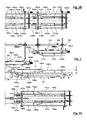
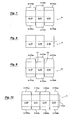
- the multi-functional packaging line subject of the present invention extends longitudinally and it is able to pack products in two-piece box like packages, obtained by means of two separate blanks, that is, a blank-tray B, see Fig. 7 , and a blank-cover A or A1, see Fig. 8 or 9 , or else it is able to package the products in packages of the so called wraparound type, obtained by a single blank-wraparound C, see fig. 10 .
- the aforementined packaging line with respect to a median horizontal plane that is substantially defined by the line II-II in Fig. 1 , at the bottom side, compries lower dual-functional positioning-conveying-forming means, indicated in the assembly by 100, comprising individual means and/or functional groups, 110, 120, 130, 140, 150, best described below; said lower dual-functional positioning-conveying-forming means, 100, can alternatively be used to insert and position a blank-tray, B, Fig. 7 , under the base of the products, and then to fold said blank-tray B around the product's base translating said blank-tray B downstream together with the product P, or else used to place a blank-wraparound C, Fig. 10 , under the base of the products P, and then to fold the bottom portion of said blank-wraparound C around the base of products P, translating said blank-wraparound C downstream together with the product P.
- This multi-functional packaging line also comprises, on the upper side, upper positioning-conveying-forming means, 200, which can be inserted or removed with respect to the multi-functional packaging line, where these upper positioning-conveying-forming means 200 are used to insert and position a blank-cover, A or A1, ( Fig. 8 or 9 ) above the top of the product P, and then to push, translate and fold this blank-cover, A or A1, on top of the product P while the product P beneath is translated downstream.
- upper positioning-conveying-forming means 200 which can be inserted or removed with respect to the multi-functional packaging line, where these upper positioning-conveying-forming means 200 are used to insert and position a blank-cover, A or A1, ( Fig. 8 or 9 ) above the top of the product P, and then to push, translate and fold this blank-cover, A or A1, on top of the product P while the product P beneath is translated downstream.
- upper forming-folding means, 300 Downstream these upper positioning-conveying-forming means, 200, there are upper forming-folding means, 300, preferably inserted and removed with respect to the packaging line, in which said upper forming-folding means 300 are mainly used to form and fold the upper portion of the blank-wraparound C ( Fig. 10 ) on top of the product P, while said blank-wraparound C and the product P beneath are translated downstream, or else they can optionally be used to positively consolidate and/or grasp the top of the cover in order to optimise the operations of closing of a two-piece packaging.
- lower dual-functional positioning-conveying-forming means 100 in their upstream zone they comprise: lower inserting-positioning means 110, first pushing-conveying means 120 and second pushing-conveying means 130.
- the lower inserting-positioning means 110 are able to insert and position, in an insertion zone Z1 of said packaging line, a blank-tray B or a blank-wraparound C.
- said lower inserting-positioning means 110 are able to insert a blank-tray B, or a blank-wraparound C, under the product P, by inserting and positioning the blank, B or C, under a sliding dead plate, 125, on whose upper surface the product P can slide, in which said product P is illustrated hereby as a lot of bottles without any limitations with respect to the other type of products, either monolithic or of other type.
- the blank-tray B is inserted in a flat configuration under the dead plate 125
- the blank-wraparound C is inserted in a folded configuration, with lower panels C-Pl and back panels C-PP horizontally coplanar to each other placed under the dead plate 125, with the front panel C-PA vertically placed in front of the front side of the product P, and with the panels C-PS and C-LC vertically placed.
- said inserting-positioning means 110 comprise a first conveyor belt, 111, which extends transversally with respect to the packaging line, preferably of the suction type or equipped with grasping means, in which the upper branch of said inserting-positioning means 110 is able to grasp the lower face of the blank-tray B or of the blank-wraparound C, and then convey and position them within said packaging line in the first zone Z1, with the eventual help of positioning-abutting means of end of stroke and/or guide means.
- a first conveyor belt, 111 which extends transversally with respect to the packaging line, preferably of the suction type or equipped with grasping means, in which the upper branch of said inserting-positioning means 110 is able to grasp the lower face of the blank-tray B or of the blank-wraparound C, and then convey and position them within said packaging line in the first zone Z1, with the eventual help of positioning-abutting means of end of stroke and/or guide means.
- said conveyor belt 111 has a first end portion, 111 a, externally placed with respect to the packaging line, and a second end portion, 111b, internally placed with respect to the packaging line, in order to feed the blanks in a single succession and in a synchronised manner with respect to the machine cycles.
- the first pushing-conveying means 120 preferably, comprise a suspended bars pushing system 121, in which said bars 121 are supported by chains 122sx and 122dx and are used to push-convey the product P downstream by sliding it over the dead plate 125.
- the second pushing-conveying means, 130 are used to push and convey the blank-tray B, or the blank-wraparound C, from the said first zone Z1 downstream along the packaging line and, in the given example, they comprise a chain 131 equipped with pushing teeth 132, in which said chain 131 travels in a closed loop with an operative upper branch extending from upstream to downstream and running into a slot 112 obtained in the end portion 110b of the conveyor belt 111 (see also fig. 1 C) .
- lower longitudinal flat-transportation means 140 Downstream from the dead plate 125 there are lower longitudinal flat-transportation means 140 which include two transport belts, 141 sx and 141 dx, preferably of suction type, transversally spaced, traveling in a closed loop, used for moving downstream the blank-tray B or the blank-wraparound C on which the product P is placed.
- the upper branch of the chain 131 with the pushing teeth 132 of the pushing-conveying means 130 is to be moved longitudinally.
- conveying-folding means 150 of the two groups with multiple chains type, 151 sx and 151dx, in which said chains are used to carry abutting-folding elements 152sx-152dx and pushing-folding elements 153sx-153dx.
- the lower conveying-folding means 150 there can also be rotating folding means, 154sx and 154dx, one or more stationary folding means, 155sx-155dx and 156sx-156dx, and lower gluers 160sx and 160dx.
- the second pushing-conveying means 130 it is preferable for the second pushing-conveying means 130 to extend longitudinally from the upstream zone of the inserting-positioning means 110 to the upstream zone of said lower conveying-folding means 150.
- upper positioning-conveying-forming means 200 which are supported from the top hanging towards the bottom by means of vertical translator means 250 used to move and position them vertically, in order to get a change in size with regards to the product's height, and, in addition, used to obtain two configurations: a) -a first operative lowered configuration, in which said positioning-conveying-forming means 200 are inserted within the packaging line and can position, convey and form covers on top of the products, and b) -a non-operative lifted configuration.
- Said upper positioning-conveying-forming means 200 can comprise: >-upper inserting-positioning means 210; >-upper pushing-conveying means 220, >-upper pushing-conveying-folding means 230.
- the upper inserting-positioning means 210 preferably driven by a servo-motor M210, are used to insert and position, in a suspended manner, in an insertion zone Z1 of the said packaging line, in a single succession and in synchronization with the packaging cycles, a blank-cover A or A1, in a folded configuration, in front of and above the product P, with the back panel A-PP and the upper panel A-PS horizontally coplanar placed above the upper side of the product P and with the front panel, A-PA, vertically placed in front of the front side of the product P.
- the inserting-positioning means 210 include a conveyor belt 211, preferably of suction type, transversally extended with respect to this packaging line, whose lower branch grasps the upper face of the upper panel A-PS and/or the back panel A-PP of the blank-cover A, and then convey it in a folded configuration into the said products packaging line and place it in the first zone Z1.
- a conveyor belt 211 preferably of suction type, transversally extended with respect to this packaging line, whose lower branch grasps the upper face of the upper panel A-PS and/or the back panel A-PP of the blank-cover A, and then convey it in a folded configuration into the said products packaging line and place it in the first zone Z1.
- This suction conveyor belt 211 preferably, has a transversal section placed into the assembly line inclined from top to bottom and downstream with respect to the product's movement, and, also, said suction conveyor belt 211 has a predetermined suction force able to maintain the blank-cover A suspended in said zone Z1, and able to allow the downstream translation of said blank-cover A held suspended by suction when an external force is applied.
- said conveyor belt 211 has a first end portion, 211 a, externally placed with respect to the packaging line, and a second end portion 211 b, internally placed with respect to the packaging line.
- the upper pushing-conveying means 220 preferably driven by the servo-motor M220, are used to push and convey the blank-cover A, in this folded configuration, from the first zone Z1 downstream along the products packaging line, as soon as the front side of the product P come against and/or near the front panel A-PA of the blank A.
- said pushing-conveying means 220 include a closed-loop travelling chain 221 equipped with pushing teeth 222, in which said chain 221 travels into a groove 212 that extends longitudinally obtained through transmission shaped like an inverted "U" of the suction conveyor belt 211.
- the upper pushing-conveying-folding means 230 preferably driven by a servo-motor a servomotor M230, are mainly used to abut the upper front edge of the front panel A-PA of the blank-cover A / A1, to convey this blank-cover A / A1 downstream along the products packaging line, and to fold the back panel A-PP of the blank-cover A against the back side of the product P.
- said upper pushing-conveying-folding means 230 include a conveyor group with multiple chains, 231 sx and 231 dx, equipped with abutting-folding elements 232sx and 232dx, and folding-pushing elements 233sx and 233dx.
- upper forming-folding means 300 which are supported from the top hanging towards the bottom by means of vertical translation means 350 used to vertically translate and position the aforementioned upper forming-folding means 300, in order to obtain a change in size with respect to the product's height, and, in addition, if desired, able to obtain two configurations: a) -a first operative lowered configuration, in which said third forming-folding means 300 are inserted within the packaging line for a positive forming of the upper portion of the two-piece packaging, or for a positive forming of the upper portion of the blank-wraparound on top of products P, and b) -a second non-operative lifted configuration.
- said upper forming-folding means 300 include a conveyor group 310, preferably driven by a servomotor M310, comprising multiple chains, 311 sx and 311 dx equipped with abutting-folding elements 312sx and 312dx and with folding-pushing elements 313sx and 313dx.
- gluers 361 sx and 361 dx there can also be rotating folding means, 320sx and 320dx, stationary folding means, 330sx and 330dx, and upper lateral gluers 361 sx and 361 dx, as well as other gluers 370 ( Fig. 6 ).
- two operational setups can be provided: >-a first setup, illustrated in Fig. 3-4 , in which the upper forming-folding means 300 are raised up and non-operational; >-or else a second setup, illustrated in Fig. 11-12 , in which the upper forming-folding means 300 are lowered down and operational.
- Fig. 3-4 excluding the closing flaps A-PAsx, A-Padx, A-PSsx, A-PSdx, A-PPsx, A-PPdx of the blank-cover A1
- a two-piece box comprising a quadrangular tray type glued with lateral edges obtained by means of a blank-tray B ( Fig. 7 ) and a cover shaped like an inverted "U" obtained by means of a blank-cover A ( Fig.
- a two-piece box comprising a glued quadrangular tray with lateral edges obtained by means of a blank-tray B ( Fig. 7 ) and a glued quadrangular cover with lateral edges obtained by means of a blank-cover A1 ( Fig.
- a two-piece box comprising a glued quadrangular tray with lateral edges obtained by means of a blank-tray B ( Fig. 7 ) and a glued quadrangular cover with lateral edges obtained by means of a blank-cover A1 ( Fig.
- the upper positioning-conveying-forming means 200 are lifted up in a non-operative position by means of translator means 250, and the following operations are executed: 4a) -the product P is pushed and conveyed downstream, sliding it over the dead plate 125 by means of a driving bar 121; 4b) -a blank-wraparound C is inserted and placed in a folded configuration in the zone Z1 by means of the conveyor belt 111 of the lower inserting-positioning means 110, with the lower and back panels C-PI and C-PP arranged under the dead plate 125, and with the front and upper panels and the closing flaps C-PA, C-PS, C-LC, placed on a vertical plane; 4c) -the blank-wraparound C is conveyed downstream, at the same linear speed as the product P, by means of the pushing tooth 132
Landscapes
- Engineering & Computer Science (AREA)
- Mechanical Engineering (AREA)
- Making Paper Articles (AREA)
- Closing Of Containers (AREA)
- Packaging Of Annular Or Rod-Shaped Articles, Wearing Apparel, Cassettes, Or The Like (AREA)
- Packages (AREA)
- Container Filling Or Packaging Operations (AREA)
Claims (43)
- Multifunktions-Verpackungsstraße, die sich in Längsrichtung erstreckt, zum Verpacken von Produkten (P) in aus zwei Teilen bestehenden Behältern, hergestellt aus einem Schachtelzuschnitt (B) und einem Deckelzuschnitt (A/A1), und zum Verpacken von Produkten (P) in Umhüllungen, hergestellt aus einem einzigen Einhüllzuschnitt (C), umfassend:- untere Doppelfunktionsmittel (100) zum Positionieren, Fördern und Formen, die alternativ eingesetzt sind zum Positionieren eines Schachtelzuschnitts (B) unter die Basis der Produkte (P) und zum anschließenden Falten des Schachtelzuschnitts (B) um die Basis der Produkte (B) durch Fördern des Schachtelzuschnitts (B) mit dem entsprechenden Produkt (P) in Arbeitsrichtung nach vom, oder zum Positionieren eines Einhüllzuschnitts (C) unter die Basis des Produkts (P) und zum Falten des unteren Abschnitts des Einhüllzuschnitts (C) um die Basis des Produkts (P) durch Fördern des Einhüllzuschnitts (C) und des entsprechenden Produkts (P) in Arbeitsrichtung nach vom,- obere Mittel (200) zum Positionieren, Fördern und Formen, die wenigstens zwei Konfigurationen einnehmen:a) eine erste Arbeitsstellung, in der diese oberen Mittel (200) einen Deckelzuschnitt (A/A1) auf das Produkt (P) legen und anschließend den Deckelzuschnitt (A/A1) in Arbeitsrichtung vorwärts bewegen, wobei sie während dieser Vorwärtsbewegung den Deckelzuschnitt (A/A1) auf der Oberseite des Produktes (P) knicken, während sich dieses vorwärts bewegt,b) eine zweite Nichtarbeitsstellung,- obere Mittel (300) zum Formen und Falten, die vor den Mitteln (200) zum Positionieren, Fördern und Formen angeordnet sind und dazu dienen, den oberen Abschnitt des Einhüllzuschnitts (C) auf der Oberseite des Produkts (P) zu knicken, während sich dieses vorwärts bewegt.
- Verpackungsstraße nach Anspruch 1, dadurch gekennzeichnet, dass die unteren Doppelfunktionsmittel (100) zum Positionieren, Fördern und Formen in ihrem hinteren Bereich aufweisen:- untere Doppelfunktionsmittel (110) zum Einführen und Positionieren, um in einer ersten Einführzone (Z1) der Verpackungsstraße einen Schachtelzuschnitt (B) oder einen Einhüllzuschnitt (C) unter eine feststehende Gleitplatte (125) zu bringen und zu positionieren,- erste untere Schub- und Transportmittel (120), die das Produkt in Arbeitsrichtung auf der fixen Gleitplatte (125) nach vom schieben,- zweite untere Schub- und Transportmittel (130), die den Schachtelzuschnitt (B) oder den Einhüllzuschnitt (C) aus der ersten Einführzone (Z1) nach vom schieben.
- Verpackungsstraße nach Anspruch 2, dadurch gekennzeichnet, dass die unteren Mittel (110) zum Einführen und Positionieren so ausgebildet sind, dass sie den Schachtelzuschnitt (B) in flacher Form unter die feststehende Gleitplatte (125) einführen.
- Verpackungsstraße nach Anspruch 2, dadurch gekennzeichnet, dass die unteren Mittel (110) zum Einführen und Positionieren so ausgebildet sind, dass sie den Einhüllzuschnitt (C) in geknickter Form einführen und positionieren, wobei sich das untere Feld (C-PI) und das hintere Feld (C-PP) komplanar horizontal unter der feststehenden Gleitplatte (125) erstrecken, während sich das vordere Feld (C-PA) vor der Vorderseite des Produktes (P) vertikal erstreckt.
- Verpackungsstraße nach einem der Ansprüche 2 bis 4, dadurch gekennzeichnet, dass die unteren Mittel (110) zum Einführen und Positionieren ein erstes Förderband (111) aufweisen, das sich quer zu der Verpackungsstraße erstreckt und dessen oberes Trum so ausgebildet ist, dass es die Unterseite des Schachtelzuschnittes (B) oder des Einhüllzuschnittes (C) erfasst, in die Verpackungsstraße überführt und dort in der ersten Zone (Z1) positioniert.
- Verpackungsstraße nach Anspruch 5, dadurch gekennzeichnet, dass das Förderband (111) ein Ansaugband ist.
- Verpackungsstraße nach Anspruch 5 oder 6, dadurch gekennzeichnet, dass das erste Förderband (111) einen ersten Endabschnitt (111a) hat, der sich außerhalb der Verpackungsstraße befindet, während ein zweiter Endabschnitt (111b) innerhalb der Verpackungsstraße angeordnet ist.
- Verpackungsstraße nach einem der Ansprüche 2 bis 7, dadurch gekennzeichnet, dass die unteren Schub- und Transportmittel (120) ein System mit aufgehängten Schubstangen (121) haben.
- Verpackungsstraße nach einem der Ansprüche 2 bis 8, dadurch gekennzeichnet, dass die unteren Schub- und Transportmittel (130) eine mit Vorschubzähnen (132) bestückte, endlos umlaufende Kette (131) aufweisen, deren oberes Trum in Arbeitsrichtung von hinten nach vom läuft und sich durch einen Schlitz (112) bewegt, der im Endabschnitt (110b) des Förderbandes (111) ausgebildet ist.
- Verpackungsstraße nach einem der vorhergehenden Ansprüche, dadurch gekennzeichnet, dass die unteren Doppelfunktionmittel (100) zum Positionieren, Fördern und Formen weiterhin einen flachen Förderer (140) haben, der in Arbeitsrichtung vor der feststehenden Gleitplatte (125) liegt.
- Verpackungsstraße nach Anspruch 10, dadurch gekennzeichnet, dass der flache Förderer (140) zwei Ansaugbänder (141sx, 141 dx) hat, die endlos umlaufen.
- Verpackungsstraße nach Anspruch 11, dadurch gekennzeichnet, dass zwischen den beiden Ansaugbändern (141sx, 141dx) das obere Trum einer Kette (131) verläuft, die sich in Längsrichtung bewegt und mit den Vorschubzähnen (132) der Schub- und Transportmittel (130) ausgestattet ist.
- Verpackungsstraße nach einem der vorhergehenden Ansprüche, dadurch gekennzeichnet, dass die unteren Doppelfunktionmittel (100) zum Positionieren, Fördern und Formen untere Förder- und Faltmittel (150) mit Anschlag- und Faltelementen (152sx, 152dx) und Vorschub- und Faltelementen (153sx, 153dx) hat.
- Verpackungsstraße nach Anspruch 13, dadurch gekennzeichnet, dass die unteren Förder- und Faltmittel (150) eine Fördereinheit mit Ketten (151sx, 151dx) haben, welche die Anschlag- und Faltelemente (152sx, 152dx) und die Vorschub- und Faltelemente (153sx, 153dx) tragen.
- Verpackungsstraße nach Anspruch 13 oder 14, dadurch gekennzeichnet, dass die unteren Förder- und Faltmittel (150) in Arbeitsrichtung vor dem flachen Förderer (140) liegen.
- Verpackungsstraße nach einem der Ansprüche 13 bis 15, dadurch gekennzeichnet, dass in der Nähe der unteren Förder- und Faltmittel (150) weitere, rotierende Faltelemente (154sx, 154dx) angeordnet sind.
- Verpackungsstraße nach einem der Ansprüche 13 bis 16, dadurch gekennzeichnet, dass in der Nähe der unteren Förder- und Faltmittel (150) weitere, stationäre Faltelemente (155sx, 155dx, 156sx, 156dx) vorgesehen sind.
- Verpackungsstraße nach einem der Ansprüche 13 bis 17, dadurch gekennzeichnet, dass sich die zweiten Schub- und Transportmittel (130) von einem Bereich vor den Mitteln (110) zum Einführen und Positionieren bis zu den unteren Förder- und Faltmitteln (150) erstrecken.
- Verpackungsstraße nach einem der vorhergehenden Ansprüche, dadurch gekennzeichnet, dass die oberen Doppelfunktionmittel (200) zum Positionieren, Fördern und Formen in die Verpackungsstraße hinein oder aus dieser heraus bewegbar sind.
- Verpackungsstraße nach einem der vorhergehenden Ansprüche, dadurch gekennzeichnet, dass die oberen Mittel (200) zum Positionieren, Fördern und Formen in hängender Stellung an vertikalen Verstellorganen (250) gehalten sind, die diese vertikal verschieben und positionieren können.
- Verpackungsstraße nach Anspruch 1, dadurch gekennzeichnet, dass die oberen Mittel (200) zum Positionieren, Fördern und Formen die folgenden Arbeitsschritte ausführen:a) Positionieren eines Deckelzuschnitts (A) in hängender Lage auf der Oberseite eines Produktes (P),b) Vorwärtsfördern des Deckelzuschnitts (A), wobei sie während dieser Vorschubbewegung den Deckelzuschnitt (A) über das Produkt (P) falten, um einen Deckel in Form eines kopfstehenden U zu bilden.
- Verpackungsstraße nach Anspruch 1, dadurch gekennzeichnet, dass die oberen Mittel (200) zum Positionieren, Fördern und Formen die folgenden Arbeitsschritte durchführen:a) Positionieren eines Deckelzuschnitts (A1) in hängender Lage auf der Oberseite eines Produktes (P),b) Vorwärtsfördern des Deckelzuschnitts (A1), wobei sie während dieses Vorschubs den Deckelzuschnitt (A1) über das Produkt (P) falten und dabei einen viereckigen Deckel mit Seitenrändern bilden.
- Verpackungsstraße nach Anspruch 1, dadurch gekennzeichnet, dass die oberen Mittel (200) zum Positionieren, Fördern und Formen die folgenden Arbeitsschritte durchführen:a) Positionieren eines Deckelzuschnitts (A1) auf dem Produkt (P),b) Vorwärtsfördern des Deckelzuschnitts (A1), wobei dieser teilweise auf der Oberseite des Produktes (P) abgekantet wird,und dass die oberen Mittel (300) zum Formen und Falten diese Arbeitsschritte beenden, um auf der Oberseite des Produktes (P) einen viereckigen Deckel zu bilden.
- Verpackungsstraße nach einem der vorhergehenden Ansprüche, dadurch gekennzeichnet, dass die oberen Mittel (200) zum Positionieren, Fördern und Formen aufweisen:- obere Mittel (210) zum Einführen und Positionieren, um in der ersten Einführzone (Z1) der Verpackungsstraße einen Deckelzuschnitt (A/A1) in geknickter Form vor und über dem Produkt (P) zu positionieren, wobei das hintere Feld (A-PP) und das obere Feld (A-PS) komplanar horizontal über der Oberseite des Produktes (P) liegen, während das vordere Feld (A-PA) vertikal vor der Vorderseite des Produktes (P) liegt,- obere Schub- und Transportmittel (220) zum Schieben und Fördern des Deckelzuschnitts (A/A1) in der gefalteten Form aus der ersten Zone (Z1) entlang der Verpackungsstraße, sobald die Vorderseite des Produktes (P) in die Nähe des vorderen Feldes (A-PA) des Zuschnittes (A/A1) kommt oder an diesem anstößt,- obere Schub-, Transport- und Faltmittel (230) zum Vorwärtsbewegen des Deckelzuschnittes (A/A1) entlang der Verpackungsstraße und zum Falten des hinteren Feldes (A-PP) des Deckelzuschnitts (A) gegen die Rückseite des Produktes (P).
- Verpackungsstraße nach Anspruch 24, dadurch gekennzeichnet, dass die oberen Mittel (210) zum Einführen und Positionieren ein zweites Förderband (211) aufweisen, das sich quer zur Verpackungsstraße erstreckt und dessen unteres Trum so ausgebildet ist, dass es die Oberseite des oberen Feldes (A-PS) und/oder des hinteren Feldes (A-PP) des Deckelzuschnitts (A/A1) erfasst, anschließend in gefalteter Form in die Verpackungsstraße führt und in der ersten Zone (Z1) positioniert.
- Verpackungsstraße nach Anspruch 25, dadurch gekennzeichnet, dass das zweite Förderband (211) ein Ansaugband ist.
- Verpackungsstraße nach den Ansprüchen 24 bis 26, dadurch gekennzeichnet, dass das zweite Förderband (211) mit seinem Querschnitt innerhalb der Verpackungsstraße liegt und in Vorschubrichtung der Produkte von oben nach unten geneigt angeordnet ist.
- Verpackungsstraße nach einem der Ansprüche 24 bis 27, dadurch gekennzeichnet, dass das zweite Förderband (211) eine vorbestimmte Ansaugkraft hat, um den hängenden Deckelzuschnitt (A/A1) in der Einführzone (Z1) zu halten und diesen während des Vorschubs in hängender Stellung zu halten, wenn eine äußere Kraft einwirkt.
- Verpackungsstraße nach einem der Ansprüche 24 bis 28, dadurch gekennzeichnet, dass das zweite Förderband (211) mit einem ersten Endabschnitt (211a) außerhalb der Verpackungsstraße liegt, während ein zweiter Endabschnitt (211b) innerhalb der Verpackungsstraße liegt.
- Verpackungsstraße nach einem der Ansprüche 24 bis 29, dadurch gekennzeichnet, dass die oberen Schub- und Transportmittel (220) eine endlos umlaufende Kette (221) mit Vorschubzähnen (222) hat, die durch einen Längsschlitz (212) läuft, der in den oberen Mitteln (210) zum Einführen und Positionieren ausgebildet ist.
- Verpackungsstraße nach einem der Ansprüche 24 bis 30, dadurch gekennzeichnet, dass die oberen Schub-, Transport- und Faltmittel (230) zum Vorschieben, Fördern und Falten eine Fördergruppe mit Ketten (231sx, 231dx) haben, die mit Anschlag- und Faltelementen (232sx, 232dx) und mit Vorschub- und Faltelementen (233sx, 233dx) ausgerüstet sind.
- Verpackungsstraße nach einem der Ansprüche 24 bis 31, dadurch gekennzeichnet, dass in der Nähe der oberen Schub-, Transport- und Faltmittel (230) weitere, rotierende Faltelemente (244sx, 244dx) angeordnet sind.
- Verpackungsstraße nach einem der Ansprüche 24 bis 32, dadurch gekennzeichnet, dass in der Nähe der oberen Schub-, Transport- und Faltmittel (230) weitere, stationäre Faltelemente (245sx, 245dx, 246sx, 246dx) angeordnet sind.
- Verpackungsstraße nach einem der vorhergehenden Ansprüche, dadurch gekennzeichnet, dass die oberen Mittel (300) zum Formen und Falten in die Verpackungsstraße einsetzbar und aus dieser entfernbar sind.
- Verpackungsstraße nach einem der vorhergehenden Ansprüche, dadurch gekennzeichnet, dass die oberen Mittel (300) zum Formen und Falten in hängender Stellung an vertikalen Verstellorganen (350) gehalten sind, die diese vertikal verschieben und positionieren können.
- Verpackungsstraße nach einem der vorhergehende Ansprüche, dadurch gekennzeichnet, dass die oberen Mittel (300) zum Formen und Falten eine Fördergruppe (310) mit Ketten (311sx, 311dx) aufweisen, die Anschlag- und Faltelemente (312sx, 312dx) sowie Vorschub- und Faltelemente (313sx, 313dx) haben.
- Verpackungsstraße nach einem der vorhergehenden Ansprüche, dadurch gekennzeichnet, dass in der Nähe der oberen Mittel (300) zum Formen und Falten rotierende Faltelemente (320sx, 320dx) angeordnet sind.
- Verpackungsstraße nach einem der vorhergehenden Ansprüche, dadurch gekennzeichnet, dass in der Nähe der oberen Mittel (300) zum Formen und Falten stationäre Faltelemente (330sx, 330dx) angeordnet sind.
- Verpackungsstraße nach einem der vorhergehenden Ansprüche, dadurch gekennzeichnet, dass in der Nähe der oberen Mittel (300) zum Formen und Falten untere, seitlich angeordnete Klebelemente (361sx, 361dx) vorgesehen sind.
- Verfahren zum Verpacken von Produkten (P) in einer Multifunktions-Verpackungsstraße nach einem der vorhergehenden Ansprüche zur Bildung eines zweiteiligen Behälters mit einer viereckigen, geklebten Schachtel mit Seitenkanten, die aus einem Schachtelzuschnitt (B) hergestellt wird, welcher ein vorderes Feld (B-PA) mit Verschlusslaschen (B-PAsx, B-PAdx), ein unteres Feld (B-PI) mit Verschlusslaschen (B-PIsx, B-PIdx) und ein hinteres Feld (B-PP) mit Verschlusslaschen (B-PPsx, B-PPdx) hat, sowie mit einem Deckel in Form eines kopfstehenden U, der aus einem Deckelzuschnitt (A) hergestellt wird, der ein vorderes Feld (A-PA), ein oberes Feld (A-PS) sowie ein hinteres Feld (A-PP) hat, wobei die folgenden Operationen durchgeführt werden:1a) das Produkt (P) wird mittels einer Schubstange (121) vorgeschoben und auf die feststehende Gleitplatte (125) vorgeschoben,1b) ein Schachtelzuschnitt (B) wird in flacher Form mit längs ausgerichteten Feldern von dem ersten Förderband (111) in der Einführzone (Z1), die innerhalb der Verpackungsstraße liegt, unter die feststehende Gleitplatte (125) gebracht und positioniert,1c) ein Deckelzuschnitt (A) wird in gefalteter Form und in von oben nach unten hängender Lage durch ein zweites Förderband (211) in die Einführzone (Z1) gebracht, so dass sich das vordere Feld (A-PA) vor dem Produkt (P) befindet,1d) der Schachtelzuschnitt (B) wird mittels eines Vorschubzahns (132) mit derselben Lineargeschwindigkeit wie das Produkt (P) vorgeschoben, wenn sich das Produkt (P) in zum unteren Feld (B-PI) des Schachtelzuschnitts (B) ausgerichteter Vertikalstellung befindet,1e) der Deckelzuschnitt (A) wird mit derselben Lineargeschwindigkeit wie das Produkt (P) mittels eines Vorschubzahns (222) vorgeschoben, wenn die Vorderseite des Produktes (P) in der Nähe des vorderen Feldes (A-PA) des Deckelzuschnitts (A) liegt oder daran anstößt, wobei während dieser Phase der Deckelzuschnitt (A) vorwärtsbewegt wird, während er an dem Saugförderband (211) festgehalten wird, um anschließend sanft auf die Oberseite des Produktes (P) zu fallen,1f) der Schachtelzuschnitt (B), das Produkt (P) und der Deckelzuschnitt (A) werden in dieser Weise über das vordere Ende der feststehenden Gleitplatte (125) weiterbewegt, worauf das Produkt (P) auf das untere Feld (B-PI) des Schachtelzuschnitts (B) fällt,1g) der Schachtelzuschnitt (B) mit dem Produkt (P) werden durch den Vorschubzahn (132) und ggf. mittels Ansaugbändern (141sx, 141dx) weiter vorgeschoben, wobei auch der Deckelzuschnitt (A) mittels des Vorschubzahns (222) in korrekter vertikaler Ausrichtung vorgeschoben wird,1h) das vordere Feld (A-PA) des Deckelzuschnitts (A) wird oben zum Anschlag an zwei Anschlag- und Faltelemente (232sx, 232dx) gebracht,1i) das hintere Feld (A-PP) des Deckelzuschnitts (A) wird mit Hilfe von zwei Vorschub- und Faltelementen (233sx, 233dx) nach unten abgewinkelt, um auf diese Weise auf dem Produkt (P) einen Deckel in Form eines kopfstehenden U zu erzeugen,11) das vordere Feld (B-PA) des Schachtelzuschnitts (B) wird mit Hilfe von zwei Anschlag- und Faltelementen (152sx, 152dx), die im unteren Bereich gegen das vordere Feld (B-PA) wirken, nach oben gefaltet,1m) die Verschlusslaschen (B-PAsx und B-PAdx) des vorderen Feldes (B-PA) werden mit Hilfe von zwei stationären Faltelementen (155sx, 155dx) nach innen umgelegt,1n) die Verschlusslaschen (B-PPsx und B-PPdx) des hinteren Feldes (B-PP) werden mit Hilfe von zwei rotierenden Faltelementen (154sx und 154dx) nach oben umgelegt,1o) das hintere Feld (B-PP) wird mit Hilfe von zwei Vorschub- und Faltelementen (153sx und 153 dx) nach oben umgelegt, wobei die Verschlusslaschen (B-PPsx und B-PPdx) innerhalb der stationären Faltelemente (155sx, 155dx) liegen,1p) mit Hilfe eines Paares seitlicher Klebelemente (160sx, 160dx) wird Klebstoff auf die unteren Bereiche der Verschlusslaschen (B-PAsx, B-PPsx und B-PAdx, B-PPdx) aufgebracht,1q) die Verschlusslaschen (B-PIsx und B-PIdx) werden mittels der stationären Faltelemente (156sx und 156 dx) nach oben umgelegt.
- Verfahren zum Verpacken von Produkten (P) in einer Multifunktions-Verpackungsstraße nach einem der Ansprüche 1 bis 39 zur Herstellung eines zweiteiligen Behälters, bestehend aus- einer viereckigen, geklebten Schachtel mit Seitenkanten, hergestellt aus einem Schachtelzuschnitt (B) mit einem vorderen Feld (B-PA) mit Verschlusslaschen (B-PAsx, B-PAdx), einem unteren Feld (B-PI) mit Verschlusslaschen (B-PIsx, B-PIdx) und einem hinteren Feld (B-PP) mit Verschlusslaschen (B-PPsx, B-PPdx), und- einem viereckigen Deckel mit Seitenkanten, hergestellt aus einem Deckelzuschnitt (A1) mit einem vorderen Feld (A-PA) mit Verschlusslaschen (A-PAsx, A-PAdx), einem oberen Feld (A-PS) mit Verschlusslaschen (A-PSsx, A-PSdx) und einem hinteren Feld (A-PP) mit Verschlusslaschen (A-PPsx, A-PPdx), wobei die folgenden Operationen durchgeführt werden:2a) das Produkt (P) wird mittels einer Schubstange (121) auf die feststehende Gleitplatte (125) vorgeschoben,2b) ein Schachtelzuschnitt (B) wird in flacher Form mit längs ausgerichteten Feldern von einem ersten Förderband (111) in der Einführzone (Z1) unter die feststehende Gleitplatte (125) gebracht und positioniert,2c) ein Deckelzuschnitt (A1) wird in gefalteter Form und in von oben nach unten hängender Lage von einem zweiten Förderband (211) in die Einführzone (Z1) der Verpackungsstraße gebracht, so dass sich das vordere Feld (A-PA) vor dem Produkt (P) befindet,2d) der Schachtelzuschnitt (B) wird mittels eines ersten Vorschubzahns (132) mit derselben Lineargeschwindigkeit wie das Produkt (P) vorgeschoben, wenn sich das Produkt (P) in zum unteren Feld (B-PI) des Schachtelzuschnitts (B) ausgerichteter Vertikalstellung befindet,2e) der Deckelzuschnitt (A1) wird mit derselben Lineargeschwindigkeit wie das Produkt (P) mittels eines zweiten Vorschubzahns (222) vorgeschoben, wenn die Vorderseite des Produktes (P) in der Nähe des vorderen Feldes (A-PA) des Deckelzuschnitts (A1) liegt oder daran anstößt, wobei während dieser Phase der Deckelzuschnitt (A1) vorwärtsbewegt wird, während er an dem Saugförderband (211) festgehalten wird, um anschließend sanft auf die Oberseite des Produktes (P) zu fallen,2f) der Schachtelzuschnitt (B), das Produkt (P) und der Deckelzuschnitt (A1) werden in dieser Weise über das vordere Ende der feststehenden Gleitplatte (125) weiterbewegt, worauf das Produkt (P) auf das untere Feld (B-PI) des Schachtelzuschnitts (B) fällt,2g) der Schachtelzuschnitt (B) mit dem Produkt (P) werden durch den ersten Vorschubzahn (132) und ggf. mittels Ansaugbändern (141sx, 141dx) weiter vorgeschoben, wobei auch der Deckelzuschnitt (A1) mittels des zweiten Vorschubzahnes (222) in korrekter vertikaler Ausrichtung vorgeschoben wird,2h) die Verschlusslaschen (A-PAsx, A-PAdx) des vorderen Feldes (A-PA) werden mittels stationärer Faltelemente (245sx und 245dx) nach innen umgelegt,2i) die Verschlusslaschen (A-PPsx, A-PPdx) des hinteren Feldes (A-PP) werden durch Faltelemente (244sx und 244 dx) nach unten umgelegt,21) das vordere Feld (A-PA) des Deckelzuschnitts (A1) wird oben zum Anschlag an zwei Anschlag- und Faltelemente (232sx, 232dx) gebracht,2m) das hintere Feld (A-PP) des Deckelzuschnitts (A1) wird mit Hilfe von zwei Vorschub- und Faltelementen (233sx, 233dx) nach unten abgewinkelt, wobei die Verschlusslaschen (A-PPsx, A-PPdx) des hinteren Feldes (A-PP) innerhalb der stationären Faltelemente (245sx, 245dx) liegen,2n) mit Hilfe eines Paares seitlicher oberer Klebelemente (160sx, 160dx) wird Klebstoff auf die oberen Bereiche der Verschlusslaschen (A-PAsx, A-PPdx und A-PAsx, A-PAdx) aufgebracht,2o) die Verschlusslaschen (A-PSsx und A-PSdx) werden mittels der stationären Faltelemente (246sx und 246 dx) nach unten umgelegt,2p) das vordere Feld (B-PA) des Schachtelzuschnitts (B) wird mit Hilfe von zwei Anschlag- und Faltelementen (152sx, 152dx), die im unteren Bereich gegen das vordere Feld (B-PA) wirken, nach oben gefaltet,2q) die Verschlusslaschen (B-PAsx und B-PAdx) des vorderen Feldes (B-PA) werden mit Hilfe von zwei stationären Faltelementen (155sx, 155dx) nach innen umgelegt,2r) die Verschlusslaschen (B-PPsx und B-PPdx) des hinteren Feldes (B-PP) werden mit Hilfe von zwei rotierenden Faltelementen (154sx und 154dx) nach oben gefaltet,2s) das hintere Feld (B-PP) wird mit Hilfe von zwei Vorschub- und Faltelementen (153sx und 153 dx) der unteren Förder- und Faltmittel (150) nach oben umgelegt,2t) mit Hilfe eines Paares seitlicher unterer Klebelemente (160dx, 160dx) wird Klebstoff auf die unteren Bereiche der Verschlusslaschen (B-PAsx, B-PPsx und B-PAdx, B-PPdx) aufgebracht,2u) die Verschlusslaschen (B-PIsx, B-PIdx) werden mittels der stationären Faltmittel (156sx, 156dx) nach oben gefaltet.
- Verfahren zum Verpacken von Produkten (P) in einer Multifunktions-Verpackungsstraße nach einem der Ansprüche 1 bis 39 zur Herstellung eines zweiteiligen Behälters, bestehend aus:- einer viereckigen, geklebten Schachtel mit Seitenkanten, hergestellt aus einem Schachtelzuschnitt (B) mit einem vorderen Feld (B-PA) mit Verschlusslaschen (B-PAsx, B-PAdx), einem unteren Feld (B-PI) mit Verschlusslaschen (B-PIsx, B-PIdx) und einem hinteren Feld (B-PP) mit Verschlusslaschen (B-PPsx, B-PPdx), und- einem viereckigen Deckel mit Seitenkanten, hergestellt aus einem Deckelzuschnitt (A1) mit einem vorderen Feld (A-PA) mit Verschlusslaschen (A-PAsx, A-PAdx), einem oberen Feld (A-PS) mit Verschlusslaschen (A-PSsx, A-PSdx) und einem hinteren Feld (A-PP) mit Verschlusslaschen (A-PPsx, A-PPdx), wobei die folgenden Operationen durchgeführt werden: 3a) das Produkt (P) wird mittels einer Schubstange (121) auf die feststehende Gleitplatte (125) vorgeschoben,3b) ein Schachtelzuschnitt (B) wird in flacher Form mit längs ausgerichteten Feldern von dem ersten Förderband (111) in der Einführzone (Z1) unter die feststehende Gleitplatte (125) gebracht und positioniert,3c) ein Deckelzuschnitt (A1) wird in gefalteter Form und in von oben nach unten hängender Lage von einem zweiten Förderband (211) in die Einführzone (Z1) gebracht, die innerhalb der Verpackungsstraße liegt, so dass sich das vordere Feld (A-PA) vor dem Produkt (P) befindet,3d) der Schachtelzuschnitt (B) wird mittels eines Vorschubzahns (132) mit derselben Lineargeschwindigkeit wie das Produkt (P) vorgeschoben, wenn sich das Produkt (P) zum unteren Feld (B-PI) des Schachtelzuschnitts (B) in ausgerichteter Vertikalstellung befindet,3e) der Deckelzuschnitt (A1) wird mit derselben Lineargeschwindigkeit wie das Produkt (P) mittels eines Vorschubzahns (222) vorwärtsbewegt, wenn die Vorderseite des Produktes (P) in der Nähe des vorderen Feldes (A-PA) des Deckelzuschnitts (A1) liegt oder daran anstößt, wobei während dieser Phase der Deckelzuschnitt (A1) vorwärtsbewegt wird, während er an dem Saugförderband (211) festgehalten wird, um anschließend sanft auf die Oberseite des Produktes (P) zu fallen,3f) der Schachtelzuschnitt (B), das Produkt (P) und der Deckelzuschnitt (A1) werden in dieser Weise über das vordere Ende der feststehenden Gleitplatte (125) weiterbewegt, worauf das Produkt (P) auf das untere Feld (B-PI) des Schachtelzuschnitts (B) fällt,3g) der Schachtelzuschnitt (B) mit dem Produkt (P) werden durch den Vorschubzahn (132) und ggf. mittels Ansaugbändern (141sx, 141dx) weiter vorgeschoben, wobei auch der Deckelzuschnitt (A1) mittels des Vorschubzahnes (222) in korrekter vertikaler Ausrichtung vorgeschoben wird,3h) die Verschlusslaschen (A-PAsx, A-PAdx) des vorderen Feldes (A-PA) werden durch Faltelemente (245sx und 245dx) nach innen umgelegt,3i) die Verschlusslaschen (A-PPsx, A-PPdx) des hinteren Feldes (A-PP) des Deckelzuschnitts (A1) werden durch Faltelemente (244sx und 244dx) nach unten umgelegt,31) das vordere Feld (A-PA) des Deckelzuschnitts (A1) wird oben zum Anschlag an zwei Anschlag- und Faltelemente (232sx, 232dx) gebracht,3m) das hintere Feld (A-PP) des Deckelzuschnitts (A1) wird mit Hilfe von zwei Vorschub- und Faltelementen (233sx, 233dx) nach unten abgewinkelt, wobei die Verschlusslaschen (A-PPsx, A-PPdx) des hinteren Feldes (A-PP) innerhalb der stationären Faltelemente (245sx, 245dx) liegen,3o) das vordere Feld (B-PA) des Schachtelzuschnitts (B) wird mit Hilfe von zwei Anschlag- und Faltelementen (152sx, 152dx), die im unteren Bereich gegen das vordere Feld (B-PA) wirken, nach oben gefaltet,3p) die Verschlusslaschen (B-PAsx und B-PAdx) des vorderen Feldes (B-PA) werden mit Hilfe von zwei Faltelementen (155sx, 155dx) nach innen umgelegt,3q) die Verschlusslaschen (B-PPsx und B-PPdx) des hinteren Feldes (B-PP) werden mit Hilfe von zwei Faltelementen (154sx und 154dx) nach oben gefaltet,3r) das hintere Feld (B-PP) des Schachtelzuschnitts (B) wird mit Hilfe von zwei Vorschub- und Faltelementen (153sx und 153 dx) nach oben umgelegt,3s) mit Hilfe eines Paares seitlicher unterer Klebelemente (160sx, 160dx) wird Klebstoff auf die unteren Bereiche der Verschlusslaschen (B-PAsx, B-PPsx und B-PAdx, B-PPdx) des vorderen Feldes (B-PA) des Schachtelzuschnitts (B) aufgebracht,3t) mit Hilfe eines Paares seitlicher oberer Klebelemente (361sx, 361dx) wird Klebstoff auf die oberen Bereiche der Verschlusslaschen (A-PAsx, A-PPsx und A-PAdx, A-PPdx) der vorderen und hinteren Felder (A-PA, A-PP) des Deckelzuschnitts (A1) aufgebracht,3u) das vordere Feld (A-PA) des Deckelzuschnitts (A1) wird oben zum Anschlag an zwei Anschlag- und Faltelemente (312sx, 312dx) gebracht,3v) das hintere Feld (A-PP) des Deckelzuschnitts (A1) wird oben zum Anschlag an zwei Vorschub- und Faltelemente (313sx, 313dx) gebracht,3x) die Verschlusslaschen (B-PIsx und B-PIdx) des unteren Feldes (B-PI) des Schachtelzuschnitts (B) werden durch Faltelemente (156sx und 156 dx) nach oben umgelegt,3y) die Verschlusslaschen (A-PSsx, A-PSdx) des oberen Feldes (A-PS) des Deckelzuschnitts (A1) werden mittels der stationären Faltelemente (330sx, 330dx) nach unten gefaltet.
- Verfahren zum Verpacken von Produkten (P) in einer Multifunktions-Verpackungsstraße nach einem der Ansprüche 1 bis 39 zur Herstellung eines einteiligen, geklebten Behälters, bestehend aus einem Einhüllzuschnitt (C) mit einer Verschlusslasche (C-LC), einem oberen Feld (C-PS) mit Verschlusslaschen (C-PSsx, C-PSdx), einem vorderen Feld (C-PA) mit Verschlusslaschen (C-PAsx, C-PAdx), einem unteren Feld (C-PI) mit Verschlusslaschen (C-PIsx, C-PIdx) und einem hinteren Feld (C-PP) mit Verschlusslaschen (C-PPsx, C-PPdx), wobei die folgenden Operationen durchgeführt werden:4a) das Produkt (P) wird mittels einer Schubstange (121) auf die feststehende Gleitplatte (125) vorgeschoben,4b) ein Einhüllzuschnitt (C) wird in gefalteter Form mittels des Förderbandes (111) der unteren Mittel (110) zum Einführen und Positionieren so in die Einführzone (Z1) gebracht, dass das untere Feld (C-PI) und das hintere Feld (C-PP) unter der feststehenden Gleitplatte (125) liegen, während das vordere Feld (C-PA), das obere Feld (C-PS) und die Verschlusslasche (C-LC) in einer vertikalen Ebene vor dem Produkt (P) angeordnet sind,4c) der Einhüllzuschnitt (C) wird mittels eines Vorschubzahns (132) mit derselben Lineargeschwindigkeit wie das Produkt (P) vorgeschoben, wenn sich das Produkt (P) in zum unteren Feld (C-PI) des Einhüllzuschnitts (C) ausgerichteter Vertikalstellung befindet,4d) der Einhüllzuschnitt (C) und das Produkt (P) werden in dieser Weise über das vordere Ende der feststehenden Gleitplatte (125) weiterbewegt, worauf das Produkt (P) auf das untere Feld (C-PI) des Einhüllzuschnitts (C) fällt,4e) der Einhüllzuschnitt (B) mit dem darauf stehenden Produkt (P) werden durch einen ersten Vorschubzahn (132) und ggf. mittels Ansaugbändern (141sx, 141dx) des flachen Förderers (140) weiter vorgeschoben,4f) das vordere Feld (C-PA) des Einhüllzuschnitts (C) wird unten zum Anschlag an zwei Anschlag- und Faltelemente (152sx, 152dx) gebracht,4g) die Verschlusslaschen (C-PAsx, C-PAdx) des vorderen Feldes (C-PA) werden durch zwei Faltelemente (155sx, 155dx) nach innen umgelegt,4h) die Verschlusslaschen (C-PPsx, C-PPdx) des hinteren Feldes (C-PP) werden durch zwei Faltelemente (154sx, 154 dx) nach oben umgelegt,4i) das hintere Feld (C-PP) wird mit Hilfe von zwei Vorschub- und Faltelementen (153sx, 153dx) der unteren Förder- und Faltmittel (150) nach oben abgewinkelt, wobei die Verschlusslaschen (C-PPsx, C-PPdx) innerhalb der Faltelemente (155sx, 155dx) liegen,41) das obere Feld (C-PS) wird mittels einer Querstange (157) nach unten abgekantet,4m) das vordere Feld (C-PA) wird oben zum Anschlag an zwei Anschlag- und Faltelemente (312sx, 312dx) gebracht,4n) über Klebelemente (370) wird Klebstoff auf die Außenseite des oberen Randes des hinteren Feldes (C-PP) aufgetragen,4o) die Verschlusslasche (C-LC) wird durch die Anschlag- und Faltelemente (312sx, 312dx) nach unten umgelegt,4p) über seitliche untere Klebelemente (160sx, 160dx) wird Klebstoff auf die unteren Bereiche der Verschlusslaschen (C-PAsx, C-PPsx und C-PAdx, C-PPdx) des vorderen Feldes (C-PA) und des hinteren Feldes (C-PP) aufgetragen,4q) über seitliche obere Klebelemente (361sx, 361dx) wird Klebstoff auf die oberen Bereiche der Verschlusslaschen (C-PAsx, C-PPsx und C-PAdx, C-PPdx) des vorderen Feldes (C-PA) aufgetragen,4r) die Verschlusslaschen (C-PIsx und C-PIdx) werden mit Hilfe von Faltelementen (156sx, 156dx) nach oben umgelegt,4s) die Verschlusslaschen (C-PSsx und C-PSdx) werden mit Hilfe von Faltelementen (330sx und 330dx) nach unten gefaltet.
Applications Claiming Priority (1)
| Application Number | Priority Date | Filing Date | Title |
|---|---|---|---|
| ITBO20070134 ITBO20070134A1 (it) | 2007-02-28 | 2007-02-28 | Linea di confezionamento multifunzionale |
Publications (2)
| Publication Number | Publication Date |
|---|---|
| EP1985541A1 EP1985541A1 (de) | 2008-10-29 |
| EP1985541B1 true EP1985541B1 (de) | 2010-04-07 |
Family
ID=39735567
Family Applications (1)
| Application Number | Title | Priority Date | Filing Date |
|---|---|---|---|
| EP20080101877 Not-in-force EP1985541B1 (de) | 2007-02-28 | 2008-02-22 | Multifunktionelle Verpackungslinie |
Country Status (4)
| Country | Link |
|---|---|
| EP (1) | EP1985541B1 (de) |
| DE (1) | DE602008000931D1 (de) |
| ES (1) | ES2344134T3 (de) |
| IT (1) | ITBO20070134A1 (de) |
Families Citing this family (2)
| Publication number | Priority date | Publication date | Assignee | Title |
|---|---|---|---|---|
| CN118753569A (zh) * | 2023-03-27 | 2024-10-11 | 楚天科技股份有限公司 | 一种覆膜模切包装机及其使用方法 |
| WO2025257764A1 (en) | 2024-06-13 | 2025-12-18 | Aetna Group S.P.A. | Packaging machine |
Family Cites Families (4)
| Publication number | Priority date | Publication date | Assignee | Title |
|---|---|---|---|---|
| US4150523A (en) * | 1977-11-15 | 1979-04-24 | Wrapmatic S.P.A. | Automatic machine for packing products of parallelepiped shape, particularly reams of paper |
| DE19512547B4 (de) * | 1995-04-06 | 2008-08-14 | Focke & Co.(Gmbh & Co. Kg) | Vorrichtung zum Herstellen und Füllen von Verpackungen aus Kartonzuschnitt mit stückigem Verpackungsgut |
| IT1315198B1 (it) * | 1999-07-09 | 2003-02-03 | Zambelli Alberto | Scatola di cartone ondulato per l'imballaggio di prodotti e metodo edapparato per la realizzazione e per l'impiego su scala industriale di |
| ITBO20000467A1 (it) * | 2000-07-31 | 2002-01-31 | Prasmatic S R L | Macchina incartonatrice di tipo wrap-around , trsformabile in vassoiatrice , con magazzino dei cartoni posto al di fuori , in linea ed all' |
-
2007
- 2007-02-28 IT ITBO20070134 patent/ITBO20070134A1/it unknown
-
2008
- 2008-02-22 ES ES08101877T patent/ES2344134T3/es active Active
- 2008-02-22 EP EP20080101877 patent/EP1985541B1/de not_active Not-in-force
- 2008-02-22 DE DE200860000931 patent/DE602008000931D1/de active Active
Also Published As
| Publication number | Publication date |
|---|---|
| ES2344134T3 (es) | 2010-08-18 |
| DE602008000931D1 (de) | 2010-05-20 |
| ITBO20070134A1 (it) | 2008-09-01 |
| EP1985541A1 (de) | 2008-10-29 |
Similar Documents
| Publication | Publication Date | Title |
|---|---|---|
| CN208559829U (zh) | 折叠装置和物品的包装设备 | |
| US2615289A (en) | Packaging method and means | |
| US7976448B2 (en) | Method and installation for assembling a composite box | |
| RU2334668C2 (ru) | Устройство и способ изготовления упаковок для сосудов | |
| CN112373115B (zh) | 一种纸盒包装成型设备 | |
| US5336040A (en) | Process and apparatus for grasping lifting and moving stacks of blanks for cigarette packs | |
| US3956868A (en) | Carton opening, filling and closing apparatus | |
| US3085377A (en) | Method and machine for packaging articles | |
| US20130090222A1 (en) | Apparatus and methods for folding paper boxes | |
| NO176432B (no) | Maskin for pakking av artikler i en emballasje | |
| US10507944B2 (en) | Machine and method for folding and adhesively bonding blanks for the production of folding boxes | |
| CA1179995A (en) | Apparatus and method for automatically packing articles in cartons | |
| US3771282A (en) | Apparatus for packaging articles | |
| EP0024451B1 (de) | Vorrichtung zum Aufbringen eines hüllenförmigen Trägers | |
| CN101631669A (zh) | 组装纸箱半成品的机器 | |
| EP1177980B1 (de) | Verpackungsmaschine | |
| KR920004013B1 (ko) | 랩어라운드식 포장기계 | |
| US4709538A (en) | Apparatus for feeding and opening a beverage carrier | |
| CN114401898B (zh) | 用于通过折叠形成容器的装置和方法 | |
| AU2007209736A1 (en) | Apparatus for collating flat objects and for conveying the collated objects further | |
| EP1985541B1 (de) | Multifunktionelle Verpackungslinie | |
| CN206085901U (zh) | 纸板分板下板输送机构和纸板封面机 | |
| CN119079223B (zh) | 自动折盒装料系统 | |
| GB2233954A (en) | Machines for packing sets of articles | |
| US3234706A (en) | Can packaging machine |
Legal Events
| Date | Code | Title | Description |
|---|---|---|---|
| PUAI | Public reference made under article 153(3) epc to a published international application that has entered the european phase |
Free format text: ORIGINAL CODE: 0009012 |
|
| AK | Designated contracting states |
Kind code of ref document: A1 Designated state(s): AT BE BG CH CY CZ DE DK EE ES FI FR GB GR HR HU IE IS IT LI LT LU LV MC MT NL NO PL PT RO SE SI SK TR |
|
| AX | Request for extension of the european patent |
Extension state: AL BA MK RS |
|
| 17P | Request for examination filed |
Effective date: 20090121 |
|
| 17Q | First examination report despatched |
Effective date: 20090305 |
|
| AKX | Designation fees paid |
Designated state(s): DE ES FR GB IT |
|
| GRAP | Despatch of communication of intention to grant a patent |
Free format text: ORIGINAL CODE: EPIDOSNIGR1 |
|
| GRAS | Grant fee paid |
Free format text: ORIGINAL CODE: EPIDOSNIGR3 |
|
| GRAA | (expected) grant |
Free format text: ORIGINAL CODE: 0009210 |
|
| AK | Designated contracting states |
Kind code of ref document: B1 Designated state(s): DE ES FR GB IT |
|
| REG | Reference to a national code |
Ref country code: GB Ref legal event code: FG4D |
|
| REF | Corresponds to: |
Ref document number: 602008000931 Country of ref document: DE Date of ref document: 20100520 Kind code of ref document: P |
|
| REG | Reference to a national code |
Ref country code: ES Ref legal event code: FG2A Ref document number: 2344134 Country of ref document: ES Kind code of ref document: T3 |
|
| PLBE | No opposition filed within time limit |
Free format text: ORIGINAL CODE: 0009261 |
|
| STAA | Information on the status of an ep patent application or granted ep patent |
Free format text: STATUS: NO OPPOSITION FILED WITHIN TIME LIMIT |
|
| 26N | No opposition filed |
Effective date: 20110110 |
|
| PGFP | Annual fee paid to national office [announced via postgrant information from national office to epo] |
Ref country code: FR Payment date: 20120228 Year of fee payment: 5 |
|
| PGFP | Annual fee paid to national office [announced via postgrant information from national office to epo] |
Ref country code: GB Payment date: 20120208 Year of fee payment: 5 |
|
| PGFP | Annual fee paid to national office [announced via postgrant information from national office to epo] |
Ref country code: ES Payment date: 20120220 Year of fee payment: 5 |
|
| GBPC | Gb: european patent ceased through non-payment of renewal fee |
Effective date: 20130222 |
|
| REG | Reference to a national code |
Ref country code: FR Ref legal event code: ST Effective date: 20131031 |
|
| PG25 | Lapsed in a contracting state [announced via postgrant information from national office to epo] |
Ref country code: GB Free format text: LAPSE BECAUSE OF NON-PAYMENT OF DUE FEES Effective date: 20130222 Ref country code: FR Free format text: LAPSE BECAUSE OF NON-PAYMENT OF DUE FEES Effective date: 20130228 |
|
| REG | Reference to a national code |
Ref country code: ES Ref legal event code: FD2A Effective date: 20140408 |
|
| PG25 | Lapsed in a contracting state [announced via postgrant information from national office to epo] |
Ref country code: ES Free format text: LAPSE BECAUSE OF NON-PAYMENT OF DUE FEES Effective date: 20130223 |
|
| PGFP | Annual fee paid to national office [announced via postgrant information from national office to epo] |
Ref country code: DE Payment date: 20180216 Year of fee payment: 11 |
|
| PGFP | Annual fee paid to national office [announced via postgrant information from national office to epo] |
Ref country code: IT Payment date: 20180220 Year of fee payment: 11 |
|
| REG | Reference to a national code |
Ref country code: DE Ref legal event code: R119 Ref document number: 602008000931 Country of ref document: DE |
|
| PG25 | Lapsed in a contracting state [announced via postgrant information from national office to epo] |
Ref country code: DE Free format text: LAPSE BECAUSE OF NON-PAYMENT OF DUE FEES Effective date: 20190903 |
|
| PG25 | Lapsed in a contracting state [announced via postgrant information from national office to epo] |
Ref country code: IT Free format text: LAPSE BECAUSE OF NON-PAYMENT OF DUE FEES Effective date: 20190222 |