EP1985886A2 - Dispositif de mesure pour un ressort à air - Google Patents
Dispositif de mesure pour un ressort à air Download PDFInfo
- Publication number
- EP1985886A2 EP1985886A2 EP08103734A EP08103734A EP1985886A2 EP 1985886 A2 EP1985886 A2 EP 1985886A2 EP 08103734 A EP08103734 A EP 08103734A EP 08103734 A EP08103734 A EP 08103734A EP 1985886 A2 EP1985886 A2 EP 1985886A2
- Authority
- EP
- European Patent Office
- Prior art keywords
- air spring
- sensor element
- measuring device
- control
- piston rod
- Prior art date
- Legal status (The legal status is an assumption and is not a legal conclusion. Google has not performed a legal analysis and makes no representation as to the accuracy of the status listed.)
- Granted
Links
Images


Classifications
-
- F—MECHANICAL ENGINEERING; LIGHTING; HEATING; WEAPONS; BLASTING
- F16—ENGINEERING ELEMENTS AND UNITS; GENERAL MEASURES FOR PRODUCING AND MAINTAINING EFFECTIVE FUNCTIONING OF MACHINES OR INSTALLATIONS; THERMAL INSULATION IN GENERAL
- F16F—SPRINGS; SHOCK-ABSORBERS; MEANS FOR DAMPING VIBRATION
- F16F9/00—Springs, vibration-dampers, shock-absorbers, or similarly-constructed movement-dampers using a fluid or the equivalent as damping medium
- F16F9/32—Details
- F16F9/3292—Sensor arrangements
-
- B—PERFORMING OPERATIONS; TRANSPORTING
- B60—VEHICLES IN GENERAL
- B60G—VEHICLE SUSPENSION ARRANGEMENTS
- B60G17/00—Resilient suspensions having means for adjusting the spring or vibration-damper characteristics, for regulating the distance between a supporting surface and a sprung part of vehicle or for locking suspension during use to meet varying vehicular or surface conditions, e.g. due to speed or load
- B60G17/02—Spring characteristics, e.g. mechanical springs and mechanical adjusting means
- B60G17/04—Spring characteristics, e.g. mechanical springs and mechanical adjusting means fluid spring characteristics
- B60G17/056—Regulating distributors or valves for hydropneumatic systems
-
- B—PERFORMING OPERATIONS; TRANSPORTING
- B60—VEHICLES IN GENERAL
- B60G—VEHICLE SUSPENSION ARRANGEMENTS
- B60G17/00—Resilient suspensions having means for adjusting the spring or vibration-damper characteristics, for regulating the distance between a supporting surface and a sprung part of vehicle or for locking suspension during use to meet varying vehicular or surface conditions, e.g. due to speed or load
- B60G17/06—Characteristics of dampers, e.g. mechanical dampers
-
- F—MECHANICAL ENGINEERING; LIGHTING; HEATING; WEAPONS; BLASTING
- F16—ENGINEERING ELEMENTS AND UNITS; GENERAL MEASURES FOR PRODUCING AND MAINTAINING EFFECTIVE FUNCTIONING OF MACHINES OR INSTALLATIONS; THERMAL INSULATION IN GENERAL
- F16F—SPRINGS; SHOCK-ABSORBERS; MEANS FOR DAMPING VIBRATION
- F16F9/00—Springs, vibration-dampers, shock-absorbers, or similarly-constructed movement-dampers using a fluid or the equivalent as damping medium
- F16F9/02—Springs, vibration-dampers, shock-absorbers, or similarly-constructed movement-dampers using a fluid or the equivalent as damping medium using gas only or vacuum
- F16F9/04—Springs, vibration-dampers, shock-absorbers, or similarly-constructed movement-dampers using a fluid or the equivalent as damping medium using gas only or vacuum in a chamber with a flexible wall
- F16F9/05—Springs, vibration-dampers, shock-absorbers, or similarly-constructed movement-dampers using a fluid or the equivalent as damping medium using gas only or vacuum in a chamber with a flexible wall the flexible wall being of the rolling diaphragm type
-
- B—PERFORMING OPERATIONS; TRANSPORTING
- B60—VEHICLES IN GENERAL
- B60G—VEHICLE SUSPENSION ARRANGEMENTS
- B60G2202/00—Indexing codes relating to the type of spring, damper or actuator
- B60G2202/10—Type of spring
- B60G2202/15—Fluid spring
- B60G2202/152—Pneumatic spring
-
- B—PERFORMING OPERATIONS; TRANSPORTING
- B60—VEHICLES IN GENERAL
- B60G—VEHICLE SUSPENSION ARRANGEMENTS
- B60G2204/00—Indexing codes related to suspensions per se or to auxiliary parts
- B60G2204/10—Mounting of suspension elements
- B60G2204/11—Mounting of sensors thereon
- B60G2204/111—Mounting of sensors thereon on pneumatic springs
Definitions
- the present invention relates to a measuring device for an air spring, in particular for a vehicle specified in the preamble of claim 1. Art. Furthermore, the invention relates to such an air spring specified in the preamble of claim 7. Art also relates to an air suspension for a vehicle Finally, the invention relates to a method for controlling such an air suspension specified in the preamble of claim 17. Art, in particular for a motor vehicle specified in the preamble of claim 16. Art.
- a plurality of measuring devices for such air springs are already known to be known.
- a measuring device is for example already in the DE 10 2004 038 239 A1 known, which is based on an optical measuring principle and disposed within the air spring.
- a reflector arranged on a cover plate of a rolling bellows is provided, which has a sensor element of an evaluation unit arranged above it corresponds visually.
- the sensor element and the measuring part designed as a reflector are movable relative to each other as a result of the application of force to the air spring or the air spring bellows while driving the motor vehicle, wherein the corresponding height distance or the corresponding change in height is detected by means of the measuring device.
- measuring devices are already known, which, for example, the DE 198 20 877 A1 and the DE 10 2005 037 725 A1 can be seen.
- ultrasonic sensors which measure the distance from a reflector component on the upper side of a piston rod integrated in the air spring shock absorber.
- the reflector component is planar in one case, hemispherical in another case.
- planar design of the reflector component Disadvantage of the planar design of the reflector component is in particular that oblique movements of the air bellows can not be detected, for example due to a horizontal application of force to the air spring, which can lead to a falsification of the measurement result.
- a disadvantage of the hemispherical design of the reflector component is that it is no longer preserved in its shape by the usually related wear over time, which also reflected accordingly in measurement errors.
- This object is achieved by a measuring device with the features of claim 1 and by an air spring with the features of claim 7.
- this object is achieved by an air suspension for a vehicle with the features of claim 16 and by a method for controlling such air suspension with the features of claim 17.
- the measuring part of a piston rod of the shock absorber is assigned to detect a relative movement between the piston rod and the sensor element to determine an air spring height (LH) is.
- LH air spring height
- the present measuring device can be used not only for an air spring for a vehicle, in particular a truck or a passenger car, but also for other vehicles such as trailers or the like. Furthermore, it is conceivable to use the measuring device with an air spring for a cabin or a cab of a truck. Finally, it is conceivable to use such a measuring device in a vehicle seat or the like.
- the measuring part has a magnetic length coding, by means of which the relative movement between the piston rod and the sensor element is to be detected.
- a length coding By means of such a length coding, the movement of the piston rod can be detected in a simple manner or the height and height change of the air spring can be determined overall by generating an evaluable magnetic alternating signal on the basis of the movement of the measuring part.
- a particularly simple embodiment of the measuring device can be realized when the measuring part is formed by a longitudinal section of the piston rod itself.
- the piston rod itself with preferably periodically alternating magnetic sections or to magnetize the piston rod accordingly, so that in this way the measuring part is formed with the corresponding length coding, which can then be detected by the sensor element.
- a further advantageous embodiment of the invention of the measuring device provides that the sensor element is formed without contact and comprises a magnetic field sensor, in particular a Hall sensor.
- a magnetic field sensor in particular a Hall sensor.
- a measuring device has proved to be advantageous in which the measuring part is designed as a reflection element and in which the sensor element comprises a transmitter-receiver unit for electromagnetic waves, in particular for microwaves, by means of which the relative movement between the piston and the sensor element to capture is.
- the sensor element comprises a transmitter-receiver unit for electromagnetic waves, in particular for microwaves, by means of which the relative movement between the piston and the sensor element to capture is.
- the measuring device is associated with a control and / or regulating unit, which is arranged within the air spring, and in particular a valve sensor unit, disposed within the air spring. This in turn results in a protected and space-saving arrangement of the measuring device - or optionally the valve sensor unit - within the air spring.
- control and / or regulating unit is connected to the sensor element via a line which runs inside the air spring.
- a line which runs inside the air spring.
- Such a power can be made particularly robust, with their secure arrangement within the air spring also ensures smooth operation of the measuring device.
- Another advantage of such a line it is beyond that the sensor element can be connected via the line to a power supply.
- control and / or regulating unit is preferably connected in a further embodiment of the invention with the sensor element via a transmitter-receiver unit, so that the two components can communicate with each other without the use of a line.
- a transmitter-receiver unit so that the two components can communicate with each other without the use of a line.
- the measuring device is assigned a control and / or regulating unit, which is arranged substantially outside the air spring, and in particular on a cover plate.
- This arrangement can be selected, for example, if the bellows of the air springs should be sized accordingly small, so that the control and / or regulating units find no place within the air spring.
- the control and / or regulating unit can be integrated outside the air spring in a valve sensor unit in order to achieve a protected and compact arrangement.
- a central control of the air suspension is provided, which communicates with the central control and / or regulating units of the associated air springs.
- the method of controlling such air suspension is further according to claim 17, that by means of the central control of the air suspension, a height value to be set at the respective air spring is transmitted to the respective decentralized control and / or regulating units.
- the central control acts only as a master to pass on desired height values of the respective air springs to the individual control and / or regulating units.
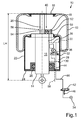
- FIGS. 1 to 3 in each case in a schematic sectional view of an air spring 10 and an air spring strut is shown in a vertically extending sectional view.
- the air spring 10 is used in the present case, for example, in a truck or passenger car. Likewise, it would also be conceivable to use the present air spring 10 for a cab suspension or a vehicle seat storage.
- the air spring 10 essentially consists of a rolling bellows 12, within which a shock absorber 14 is received.
- the rolling bellows 12 is sealingly connected on the one hand to the shock absorber 14 and on the other hand with respect to a cover plate 16 for attaching the air spring 10 to the vehicle body.
- a surrounding the rolling bellows 12 retaining cylinder is about it in the FIGS. 1 to 3 not shown.
- the shock absorber 14 comprises a damper cylinder 18 within which an axially oscillatable piston rod 20 of a piston 21 (FIG. Fig. 5 ) is recorded.
- the damper cylinder 18 of the shock absorber 14 is accommodated coaxially within a receiving cylinder 22 which is closed by a cover 24 downwards.
- a radially encircling seal 26 is provided between the cover 24 and the damper cylinder 18, in the region of which the shock absorber 14 projects through the cover 24.
- On the underside of the lid 24, an additional ring 80 can be seen, which supports the assembly with the rolling bellows 12 and the receiving cylinder 22 relative to the shock absorber 14.
- FIGS. 1 to 3 merely as schematic representation in this point.
- valve sensor unit 28 is arranged within the air spring 10, more precisely, within the receiving cylinder 22, a valve sensor unit 28 is arranged.
- the boundary of the valve sensor unit 28 is schematically indicated by dashed lines 30 upwards and downwards.
- a valve sensor unit 28 is for example already in the DE 10 2006 005 471 A1 be known, the disclosure of which is hereby expressly considered to be included.
- the valve sensor unit 28 includes, among other things, a holding valve 32, which in the in the DE 10 2006 005 471 A1 described manner by an unrecognizable pilot valve is to act on which compressed air from a central compressed air reservoir 34 or from the air spring 10 is applied.
- valve sensor unit 28 comprises in the DE 10 2006 005 471 A1 manner described a pressure regulator, via which at least the compressed air from the air spring 10, but preferably from the compressed air reservoir 34, to regulate or reduce. In this way it can be achieved that a pilot valve with a small solenoid power can be used.
- a pilot valve with a small solenoid power can be used.
- valve sensor unit 28 In addition to the magnetically switchable holding valve 32 is from the valve sensor unit 28, a pressure sensor 36 can be seen, by means of which a pressure within the air spring 10 - more precisely within the receiving cylinder 22 - to determine and its function in connection with the subject DE 10 2006 005 471 A1 already described. Finally, a control and / or regulating unit 38 of a measuring device 40 explained in greater detail below is explicitly illustrated by the valve sensor unit 28, which in the present case is integrated directly into the valve sensor unit 28. The valve sensor unit 28 is finally connected via a main valve 42 to the compressed air reservoir 34 via the compressed air line 44, so that in the present case only one connection within the cover 24 of the air spring 10 must be provided. In the area of the main valve 42, a silencer 46 can be seen.
- the control and / or regulating unit 38 which is arranged within the valve sensor unit 28, is part of the measuring device 40, which moreover comprises, as an essential component, a sensor element 48 which, adjacent to the piston rod 20, in the embodiment according to FIG. 1 the upper side of a lid 50 of the damper cylinder 18 is fixed.
- a sensor carrier 52 is used for this purpose.
- the sensor element 48 corresponds to a schematically indicated magnetic length coding 54 of a measuring part 56, which is assigned to a piston rod 20.
- the measuring part 56 may be attached to the piston rod 20 or - as in the present case - be formed by a longitudinal section of the piston rod 20 itself.
- the length coding 54 is formed in the present case by alternating magnetic sections being arranged in a constant period. These magnetically changing sections generate during a movement of the piston rod - in particular as a result of a force applied while driving the motor vehicle - an alternating signal, which is used to determine the height or determination of an air spring height LH of the air spring 10.
- the sensor element 48 which is presently designed as a magnetic field sensor in the form of a Hall sensor, via an electric line 58 of the valve sensor unit 28 - and there in particular with the control and / or regulating unit 38.
- the valves of the valve sensor unit 28 - ie in particular the holding valve 32 shown and the pilot valve, not shown - are controllable.
- the electric line 58 emerges from the cover 24 in the region of the compressed-air line 44.
- the piston rod 20 is provided with a permanent magnetic coding, wherein the contactless magnetic field sensor of the sensor element 48 by pulse counting the mounted in the region of the measuring part 56 to the piston rod 20 length encoding 54 monitors their movement and thus the hub or the only schematically indicated air spring height LH or the change measures.
- the measuring part or the length coding on the piston 21.
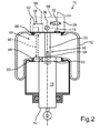
- the embodiment according to FIG. 2 differs from the one according to FIG. 1 in particular in that the sensor element 48 is integrated directly into the cover 50 of the damper cylinder 18.
- the sensor element 48 is associated with a component 60 of a transmitter-receiver unit 62, which - as shown by the dashed lines 64 - communicates with another component 66 of the transmitter-receiver unit 62, which in turn the underside of the cover plate 16 and within the rolling bellows 12 is arranged.
- the component 66 is assigned to the control and / or regulating unit 38, which in the present case-together with the valve-sensor unit 28 symbolized by the dot-dash lines 68 -is arranged on the upper side of the cover plate 16.
- the valve sensor unit 28 is arranged outside the air spring 10 or the rolling bellows 12, the valve sensor unit 28 in turn being assigned to the control and / or regulating unit 38.
- a variant is shown, in which the signal detected by means of the sensor element 48 is transmitted by the transmitter-receiver unit 62 to the valve sensor unit 28.
- FIG. 2 it can be seen that the component 66 associated with the control and / or regulating unit 38 can be positioned in a simple manner by positioning the valve sensor unit 28 above the cover plate and pushing the component 66 therethrough.
- the holding valve 42 and the compressed air sensor 36 can be seen, which can also communicate through an opening in the cover 16 with the gas space of the rolling bellows 12.
- the other pneumatic components of the valve sensor unit 28 are in FIG. 2 not recognizable, however, in the present case also a basic structure is selected, which from the DE 10 2006 005 471 A1 is known.
- the transmitter-receiver unit 62 is implemented in the present case in RFID technology, wherein the power supply, for example via a reader, which is integrated into the component 66.
- transceiver unit 62 is in the embodiment according to FIG. 3 provided to connect the sensor element 48 via a line 70 to the control and / or regulating unit 38.
- This line 70 can also be used to power the sensor element 48. It can be seen that the line 70 in this case is formed meander-shaped, so that a corresponding stroke can be compensated. Of course, it is also clear that the line 70 is designed accordingly flexible.
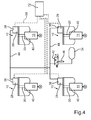
- FIG. 4 in a schematic representation of a circuit arrangement of an air suspension for a motor vehicle, in this case a truck, shown with four air springs 10.
- the four air springs 10 comprise a respective associated valve sensor unit 28, which in each case a corresponding control and / or regulating unit 38 is assigned in the manner described above.
- the four valve sensor units 28 are connected via respective compressed air lines 44 with each other or with the already in FIG. 1 explained main valve 42 and the central compressed air reservoir 34 is connected.
- each of the air springs 10 is to be controlled separately by the respective separate electronics of the control and / or regulating unit 38.
- the central controller 72 acts as a master, which transmits a desired value for the required respective height of the air spring 10 to the respective electronics of the control and / or regulating unit 38.
- the valve sensor unit 28 acts as a slave module, the predetermined by the central controller 72 and regulated by the respective control and / or regulating unit 38 height of the air spring is adjusted. The monitoring of the height also takes place by means of the respective control and / or regulating unit 38.
- a method for controlling the air suspension of the motor vehicle wherein the central controller 72 acts as a master and a certain way for the Luftfederbein height to the respective decentralized electronics of the control and / or regulating unit 38 passes each of the air springs, wherein the Height control in dependence of the measured value on the piston rod 20 takes place.
- the controller 72 merely acting as a master in order to transmit the desired height values to the individual control and / or regulating units 38.
- FIG. 5 is a schematic sectional view of the air spring 10 according to the FIGS. 1 to 3 wherein an alternative measuring device 40 is provided, in which the sensor element 48 is arranged on an end face 76 within the damper cylinder 18 and comprises a transmitter-receiver unit, by means of which electromagnetic waves, and in particular microwaves, in the direction of the end side 78th arranged to the piston 21, designed as a reflection element measuring part 56 to send or the reflected waves are to be received. It can thus be seen that the relative movement between the piston 21 and the sensor element 48 can be detected to determine the air spring height LH or its change.
- the sensor element 48 is arranged on an end face 76 within the damper cylinder 18 and comprises a transmitter-receiver unit, by means of which electromagnetic waves, and in particular microwaves, in the direction of the end side 78th arranged to the piston 21, designed as a reflection element measuring part 56 to send or the reflected waves are to be received.
- control and / or regulating unit 38 which is connected to the sensor element 48 or the transmitter-receiver unit.
- the control and / or regulating unit 38 and the sensor element 48 are formed as part of the valve sensor unit 28, which is arranged on the underside of the damper cylinder 18 and comprises the components (valves, etc.) already described.
Landscapes
- Engineering & Computer Science (AREA)
- General Engineering & Computer Science (AREA)
- Mechanical Engineering (AREA)
- Vehicle Body Suspensions (AREA)
- Fluid-Damping Devices (AREA)
Priority Applications (1)
| Application Number | Priority Date | Filing Date | Title |
|---|---|---|---|
| SI200830822T SI1985886T1 (sl) | 2007-04-27 | 2008-04-25 | Merilna naprava za pnevmatsko vzmet |
Applications Claiming Priority (1)
| Application Number | Priority Date | Filing Date | Title |
|---|---|---|---|
| DE200710020043 DE102007020043B4 (de) | 2007-04-27 | 2007-04-27 | Messeinrichtung für eine Luftfeder, Luftfederung für ein Fahrzeug sowie Verfahren zu deren Steuerung |
Publications (3)
| Publication Number | Publication Date |
|---|---|
| EP1985886A2 true EP1985886A2 (fr) | 2008-10-29 |
| EP1985886A3 EP1985886A3 (fr) | 2009-08-19 |
| EP1985886B1 EP1985886B1 (fr) | 2012-10-24 |
Family
ID=39665990
Family Applications (1)
| Application Number | Title | Priority Date | Filing Date |
|---|---|---|---|
| EP20080103734 Active EP1985886B1 (fr) | 2007-04-27 | 2008-04-25 | Dispositif de mesure pour un ressort à air |
Country Status (3)
| Country | Link |
|---|---|
| EP (1) | EP1985886B1 (fr) |
| DE (1) | DE102007020043B4 (fr) |
| SI (1) | SI1985886T1 (fr) |
Cited By (4)
| Publication number | Priority date | Publication date | Assignee | Title |
|---|---|---|---|---|
| WO2010034561A1 (fr) * | 2008-09-25 | 2010-04-01 | Contitech Luftfedersysteme Gmbh | Dispositif d’identification pour un ressort pneumatique |
| EP2754916A1 (fr) * | 2013-01-11 | 2014-07-16 | Miro Gudzulic | Unité d'amortisseur pneumatique pour une installation d'amortisseur pneumatique d'un véhicule |
| DE102016225218A1 (de) * | 2016-12-16 | 2018-06-21 | Zf Friedrichshafen Ag | Stoßdämpfer oder Federdämpfer |
| DE102017106988A1 (de) | 2017-03-31 | 2018-10-04 | Miro Gudzulic | Feder-Dämpfer-Einrichtung, insbesondere für ein Fahrzeug |
Families Citing this family (9)
| Publication number | Priority date | Publication date | Assignee | Title |
|---|---|---|---|---|
| DE102010030762A1 (de) * | 2010-06-30 | 2012-01-05 | Zf Friedrichshafen Ag | Vorrichtung zum Messen des Lagerspiels eines Kugelgelenks |
| US9352630B2 (en) * | 2012-08-31 | 2016-05-31 | Firestone Industrial Products Company, Llc | Jounce bumpers and spring assemblies including same |
| US10464385B2 (en) | 2012-08-31 | 2019-11-05 | Firestone Industrial Products Company, Llc | Jounce bumpers and spring assemblies including same |
| US9579944B2 (en) * | 2014-09-25 | 2017-02-28 | Tenneco Automotive Operating Company Inc. | System and method for attaching a control element of an air spring with internal height regulating valve |
| DE102016005539B4 (de) | 2016-05-04 | 2023-10-26 | Zf Cv Systems Hannover Gmbh | Elektronische Niveauregelungsvorrichtung für luftgefederte Fahrzeuge, Verfahren und Steuereinheit zur elektronischen Niveauregelung |
| DE102016118576B4 (de) * | 2016-09-30 | 2022-12-29 | Miro Gudzulic | Schaltventileinheit für eine Luftfedereinheit einer Luftfederanlage |
| DE102017205000A1 (de) | 2017-03-24 | 2018-09-27 | Zf Friedrichshafen Ag | Messeinrichtung für einen Schwingungsdämpfer |
| DE102019214092A1 (de) | 2019-09-17 | 2021-03-18 | Contitech Luftfedersysteme Gmbh | Luftfeder mit einem innerhalb eines Federbalgs angeordneten Sensormodul |
| DE102023129680A1 (de) * | 2023-10-27 | 2025-04-30 | Zf Cv Systems Europe Bv | Sensoreinrichtung mit passivem Sensor, Fahrzeugbaugruppe und Fahrzeug |
Citations (5)
| Publication number | Priority date | Publication date | Assignee | Title |
|---|---|---|---|---|
| DE19820877A1 (de) | 1998-05-09 | 1999-11-18 | Contitech Luftfedersyst Gmbh | Berührungslose Abstands- und Druckmessung innerhalb einer Luftfeder |
| DE10200632B4 (de) | 2002-01-10 | 2004-05-27 | Thyssenkrupp Bilstein Gmbh | Luftfederbein |
| DE102004038239A1 (de) | 2004-08-05 | 2006-03-16 | Vibracoustic Gmbh & Co. Kg | Luftfeder mit integrierter optischer Höhenstandssensorik |
| DE102006005471A1 (de) | 2005-02-10 | 2006-08-31 | Gudzulic, Miro, Dipl.-Ing. (FH) | Dezentrale Niveaufederungsanlage für Kraft- und Schienenfahrzeuge |
| DE102005037725A1 (de) | 2005-08-10 | 2007-02-22 | Contitech Luftfedersysteme Gmbh | Luftfeder mit Ultraschall-Höhenmesseinrichtung |
Family Cites Families (4)
| Publication number | Priority date | Publication date | Assignee | Title |
|---|---|---|---|---|
| JP2587631B2 (ja) * | 1987-03-20 | 1997-03-05 | トキコ株式会社 | 車高調整装置 |
| DE4413341C2 (de) * | 1994-04-18 | 1999-08-26 | Continental Ag | Meßeinrichtung mit einem Magnetfeldsensor zum berührungslosen Erfassen des lichten Abstandes zwischen zwei Bauteilen und deren Verwendung |
| DE10020764A1 (de) * | 1999-07-21 | 2001-01-25 | Mannesmann Sachs Ag | Berührungslose Abstandsermittlung zwischen Achse und Aufbau eines Fahrzeugs |
| DE10023622B4 (de) * | 2000-05-13 | 2004-11-25 | Continental Aktiengesellschaft | Kraftfahrzeug-Luftfeder mit integriertem Niveausensor |
-
2007
- 2007-04-27 DE DE200710020043 patent/DE102007020043B4/de active Active
-
2008
- 2008-04-25 SI SI200830822T patent/SI1985886T1/sl unknown
- 2008-04-25 EP EP20080103734 patent/EP1985886B1/fr active Active
Patent Citations (5)
| Publication number | Priority date | Publication date | Assignee | Title |
|---|---|---|---|---|
| DE19820877A1 (de) | 1998-05-09 | 1999-11-18 | Contitech Luftfedersyst Gmbh | Berührungslose Abstands- und Druckmessung innerhalb einer Luftfeder |
| DE10200632B4 (de) | 2002-01-10 | 2004-05-27 | Thyssenkrupp Bilstein Gmbh | Luftfederbein |
| DE102004038239A1 (de) | 2004-08-05 | 2006-03-16 | Vibracoustic Gmbh & Co. Kg | Luftfeder mit integrierter optischer Höhenstandssensorik |
| DE102006005471A1 (de) | 2005-02-10 | 2006-08-31 | Gudzulic, Miro, Dipl.-Ing. (FH) | Dezentrale Niveaufederungsanlage für Kraft- und Schienenfahrzeuge |
| DE102005037725A1 (de) | 2005-08-10 | 2007-02-22 | Contitech Luftfedersysteme Gmbh | Luftfeder mit Ultraschall-Höhenmesseinrichtung |
Cited By (7)
| Publication number | Priority date | Publication date | Assignee | Title |
|---|---|---|---|---|
| WO2010034561A1 (fr) * | 2008-09-25 | 2010-04-01 | Contitech Luftfedersysteme Gmbh | Dispositif d’identification pour un ressort pneumatique |
| US8866591B2 (en) | 2008-09-25 | 2014-10-21 | Contitech Luftfedersysteme Gmbh | Identification device for a pneumatic spring |
| US9833947B2 (en) | 2008-09-25 | 2017-12-05 | Contitech Luftfedersysteme Gmbh | Method for making an air spring member |
| EP2754916A1 (fr) * | 2013-01-11 | 2014-07-16 | Miro Gudzulic | Unité d'amortisseur pneumatique pour une installation d'amortisseur pneumatique d'un véhicule |
| DE102016225218A1 (de) * | 2016-12-16 | 2018-06-21 | Zf Friedrichshafen Ag | Stoßdämpfer oder Federdämpfer |
| DE102017106988A1 (de) | 2017-03-31 | 2018-10-04 | Miro Gudzulic | Feder-Dämpfer-Einrichtung, insbesondere für ein Fahrzeug |
| WO2018178287A1 (fr) | 2017-03-31 | 2018-10-04 | Miro Gudzulic | Dispositif amortisseur à ressort, notamment pour un véhicule |
Also Published As
| Publication number | Publication date |
|---|---|
| DE102007020043B4 (de) | 2014-05-28 |
| DE102007020043A1 (de) | 2008-10-30 |
| EP1985886B1 (fr) | 2012-10-24 |
| EP1985886A3 (fr) | 2009-08-19 |
| SI1985886T1 (sl) | 2013-04-30 |
Similar Documents
| Publication | Publication Date | Title |
|---|---|---|
| EP1985886B1 (fr) | Dispositif de mesure pour un ressort à air | |
| DE102008064647B4 (de) | Messeinrichtung für eine Luftfeder | |
| DE102011000668B4 (de) | Verfahren zur Fahrerunterstützung bei einem Andock-Vorgang eines Nutzfahrzeugs an einer Rampe | |
| EP1178892A1 (fr) | Amortisseur pneumatique a capteur de hauteur | |
| EP2005009B1 (fr) | Dispositif de surveillance et/ou de réglage du mouvement d'un composant fluide dans un système fluide | |
| DE102004055856A1 (de) | Vorrichtung zur Schätzung der Schwerpunktlage eines Fahrzeugs | |
| DE10356402B4 (de) | Verfahren zur Bestimmung der Absolutposition von einem beweglichen Bauteil | |
| DE102010002333A1 (de) | Fahrwerksensor | |
| DE102016110615A1 (de) | Sensoreinrichtung zum Erfassen der Position zweier relativ zueinander verschiebbarer Bauteile | |
| DE102013108593B4 (de) | Luftfedereinheit für eine Luftfederanlage eines Fahrzeugs | |
| EP3448729B1 (fr) | Dispositif de détection électronique de la charge par essieu d'un véhicule automobile | |
| DE102007057822B4 (de) | Regelungsverfahren für ein Fahrwerk eines Kraftfahrzeugs | |
| EP1983325B1 (fr) | Dispositif de régulation de la position d'un véhicule automobile | |
| DE102004059653B4 (de) | Bewegungsdämpfer | |
| EP2355991B1 (fr) | Procédé permettant de vérifier une soupape de suspension pneumatique pour un véhicule. | |
| DE10116638A1 (de) | Belastungsüberwachungsvorrichtung für Trittbretter | |
| EP3633196B1 (fr) | Mesure du mouvement verticale | |
| EP3648995B1 (fr) | Ressort à air, en particulier pour véhicules de route et/ou pour matériel ferroviaire | |
| DE102008042751A1 (de) | Dämpfer für ein Fahrzeug und Betriebsverfahren für einen Fahrzeugdämpfer | |
| DE102011107970A1 (de) | Sensor zur Erfassung der Niveaulage eines durch eine Luftfeder abgestützten Aufbaus insbesondere eines Kraftfahrzeugs | |
| DE102021105800A1 (de) | Steuervorrichtung sowie Verfahren zum Verändern der Geschwindigkeit eines Kraftfahrzeuges | |
| DE19503250B4 (de) | Niveauregelvorrichtung für Radaufhängungen von Kraftfahrzeugen | |
| EP4304903B1 (fr) | Dispositif de freinage d'un véhicule avec un dispositif de pédale de frein de service avec un dispositif de détection de position inductif | |
| DE102009051989A1 (de) | Stoßdämpfungsvorrichtung für ein Kraftfahrzeug | |
| DE102023106891A1 (de) | Elektronische Steuereinheit einer Niveauregulierungseinrichtung eines Fahrzeugs so-wie Verfahren zur Achslastermittlung mit einer solchen Steuereinheit |
Legal Events
| Date | Code | Title | Description |
|---|---|---|---|
| PUAI | Public reference made under article 153(3) epc to a published international application that has entered the european phase |
Free format text: ORIGINAL CODE: 0009012 |
|
| AK | Designated contracting states |
Kind code of ref document: A2 Designated state(s): AT BE BG CH CY CZ DE DK EE ES FI FR GB GR HR HU IE IS IT LI LT LU LV MC MT NL NO PL PT RO SE SI SK TR |
|
| AX | Request for extension of the european patent |
Extension state: AL BA MK RS |
|
| PUAL | Search report despatched |
Free format text: ORIGINAL CODE: 0009013 |
|
| AK | Designated contracting states |
Kind code of ref document: A3 Designated state(s): AT BE BG CH CY CZ DE DK EE ES FI FR GB GR HR HU IE IS IT LI LT LU LV MC MT NL NO PL PT RO SE SI SK TR |
|
| AX | Request for extension of the european patent |
Extension state: AL BA MK RS |
|
| RAP1 | Party data changed (applicant data changed or rights of an application transferred) |
Owner name: VEYANCE TECHNOLOGIES EUROPE, D.O.O. Owner name: GUDZULIC, MIRO |
|
| 17P | Request for examination filed |
Effective date: 20100218 |
|
| AKX | Designation fees paid |
Designated state(s): DE FR SE SI TR |
|
| 17Q | First examination report despatched |
Effective date: 20100922 |
|
| GRAP | Despatch of communication of intention to grant a patent |
Free format text: ORIGINAL CODE: EPIDOSNIGR1 |
|
| RIN1 | Information on inventor provided before grant (corrected) |
Inventor name: SIVEC, MATJAZ Inventor name: GUDZULIC, MIRO Inventor name: KOSIR, MATEJ |
|
| GRAS | Grant fee paid |
Free format text: ORIGINAL CODE: EPIDOSNIGR3 |
|
| GRAA | (expected) grant |
Free format text: ORIGINAL CODE: 0009210 |
|
| AK | Designated contracting states |
Kind code of ref document: B1 Designated state(s): DE FR SE SI TR |
|
| REG | Reference to a national code |
Ref country code: SE Ref legal event code: TRGR |
|
| REG | Reference to a national code |
Ref country code: DE Ref legal event code: R096 Ref document number: 502008008473 Country of ref document: DE Effective date: 20121220 |
|
| PLBE | No opposition filed within time limit |
Free format text: ORIGINAL CODE: 0009261 |
|
| STAA | Information on the status of an ep patent application or granted ep patent |
Free format text: STATUS: NO OPPOSITION FILED WITHIN TIME LIMIT |
|
| 26N | No opposition filed |
Effective date: 20130725 |
|
| REG | Reference to a national code |
Ref country code: DE Ref legal event code: R097 Ref document number: 502008008473 Country of ref document: DE Effective date: 20130725 |
|
| REG | Reference to a national code |
Ref country code: FR Ref legal event code: PLFP Year of fee payment: 8 |
|
| REG | Reference to a national code |
Ref country code: FR Ref legal event code: PLFP Year of fee payment: 9 |
|
| REG | Reference to a national code |
Ref country code: FR Ref legal event code: PLFP Year of fee payment: 10 |
|
| REG | Reference to a national code |
Ref country code: FR Ref legal event code: PLFP Year of fee payment: 11 |
|
| PGFP | Annual fee paid to national office [announced via postgrant information from national office to epo] |
Ref country code: DE Payment date: 20250430 Year of fee payment: 18 |
|
| PGFP | Annual fee paid to national office [announced via postgrant information from national office to epo] |
Ref country code: FR Payment date: 20250424 Year of fee payment: 18 |
|
| PGFP | Annual fee paid to national office [announced via postgrant information from national office to epo] |
Ref country code: TR Payment date: 20250421 Year of fee payment: 18 |
|
| PGFP | Annual fee paid to national office [announced via postgrant information from national office to epo] |
Ref country code: SI Payment date: 20250417 Year of fee payment: 18 Ref country code: SE Payment date: 20250429 Year of fee payment: 18 |