EP1986207B9 - Schalter und elektronisches gerät damit - Google Patents
Schalter und elektronisches gerät damit Download PDFInfo
- Publication number
- EP1986207B9 EP1986207B9 EP07714430A EP07714430A EP1986207B9 EP 1986207 B9 EP1986207 B9 EP 1986207B9 EP 07714430 A EP07714430 A EP 07714430A EP 07714430 A EP07714430 A EP 07714430A EP 1986207 B9 EP1986207 B9 EP 1986207B9
- Authority
- EP
- European Patent Office
- Prior art keywords
- switch
- supporting sections
- sheet
- switch according
- wiring
- Prior art date
- Legal status (The legal status is an assumption and is not a legal conclusion. Google has not performed a legal analysis and makes no representation as to the accuracy of the status listed.)
- Not-in-force
Links
- 229910052751 metal Inorganic materials 0.000 claims abstract description 21
- 239000002184 metal Substances 0.000 claims abstract description 21
- 238000000465 moulding Methods 0.000 claims abstract description 17
- 239000011347 resin Substances 0.000 claims description 9
- 229920005989 resin Polymers 0.000 claims description 9
- 230000002093 peripheral effect Effects 0.000 claims description 8
- 230000000994 depressogenic effect Effects 0.000 claims description 6
- 239000004020 conductor Substances 0.000 abstract description 45
- 230000000694 effects Effects 0.000 abstract description 6
- 239000000463 material Substances 0.000 description 10
- 239000000758 substrate Substances 0.000 description 9
- 238000004519 manufacturing process Methods 0.000 description 5
- 230000015572 biosynthetic process Effects 0.000 description 3
- 230000006866 deterioration Effects 0.000 description 3
- 230000007257 malfunction Effects 0.000 description 3
- FYYHWMGAXLPEAU-UHFFFAOYSA-N Magnesium Chemical compound [Mg] FYYHWMGAXLPEAU-UHFFFAOYSA-N 0.000 description 2
- 238000004026 adhesive bonding Methods 0.000 description 2
- 229910052782 aluminium Inorganic materials 0.000 description 2
- XAGFODPZIPBFFR-UHFFFAOYSA-N aluminium Chemical compound [Al] XAGFODPZIPBFFR-UHFFFAOYSA-N 0.000 description 2
- 239000000470 constituent Substances 0.000 description 2
- 238000010276 construction Methods 0.000 description 2
- 230000005489 elastic deformation Effects 0.000 description 2
- 239000013013 elastic material Substances 0.000 description 2
- 229910052749 magnesium Inorganic materials 0.000 description 2
- 239000011777 magnesium Substances 0.000 description 2
- 238000003825 pressing Methods 0.000 description 2
- 229910001069 Ti alloy Inorganic materials 0.000 description 1
- 238000005452 bending Methods 0.000 description 1
- 239000002131 composite material Substances 0.000 description 1
- 238000007796 conventional method Methods 0.000 description 1
- 238000010586 diagram Methods 0.000 description 1
- 238000009413 insulation Methods 0.000 description 1
- 238000005304 joining Methods 0.000 description 1
- 239000012778 molding material Substances 0.000 description 1
- 239000012768 molten material Substances 0.000 description 1
- 230000001681 protective effect Effects 0.000 description 1
- 238000000926 separation method Methods 0.000 description 1
- 229910000679 solder Inorganic materials 0.000 description 1
- 239000010935 stainless steel Substances 0.000 description 1
- 229910001220 stainless steel Inorganic materials 0.000 description 1
Images



Classifications
-
- H—ELECTRICITY
- H01—ELECTRIC ELEMENTS
- H01H—ELECTRIC SWITCHES; RELAYS; SELECTORS; EMERGENCY PROTECTIVE DEVICES
- H01H13/00—Switches having rectilinearly-movable operating part or parts adapted for pushing or pulling in one direction only, e.g. push-button switch
- H01H13/70—Switches having rectilinearly-movable operating part or parts adapted for pushing or pulling in one direction only, e.g. push-button switch having a plurality of operating members associated with different sets of contacts, e.g. keyboard
- H01H13/84—Switches having rectilinearly-movable operating part or parts adapted for pushing or pulling in one direction only, e.g. push-button switch having a plurality of operating members associated with different sets of contacts, e.g. keyboard characterised by ergonomic functions, e.g. for miniature keyboards; characterised by operational sensory functions, e.g. sound feedback
- H01H13/85—Switches having rectilinearly-movable operating part or parts adapted for pushing or pulling in one direction only, e.g. push-button switch having a plurality of operating members associated with different sets of contacts, e.g. keyboard characterised by ergonomic functions, e.g. for miniature keyboards; characterised by operational sensory functions, e.g. sound feedback characterised by tactile feedback features
-
- H—ELECTRICITY
- H01—ELECTRIC ELEMENTS
- H01H—ELECTRIC SWITCHES; RELAYS; SELECTORS; EMERGENCY PROTECTIVE DEVICES
- H01H2215/00—Tactile feedback
- H01H2215/004—Collapsible dome or bubble
- H01H2215/02—Reversed domes
-
- H—ELECTRICITY
- H01—ELECTRIC ELEMENTS
- H01H—ELECTRIC SWITCHES; RELAYS; SELECTORS; EMERGENCY PROTECTIVE DEVICES
- H01H2223/00—Casings
- H01H2223/008—Casings metallic
Definitions
- the present invention relates to a casing structure for accommodating functional components of a small mobile terminal and a switch having the same, - and more particularly, to a switch structure helping to achieve an improved feeling of click.
- a tendency toward downsizing and thinning is being accelerated.
- a mobile terminal such as a mobile phone, a personal handy phone system (PHS), and a personal digital assistant (PDA)
- PDA personal digital assistant
- a tendency toward downsizing and thinning is being accelerated.
- development has been advanced about downsizing and thinning of functional components for forming the same, thinning of a printed circuit board on which the functional components are mounted, downsizing of an antenna system, a reduction in wall thickness and thinning of a casing accommodating the functional components, the printed circuit board, etc., and the like.
- Fig. 8 is a sectional view of the switch section of a conventional mobile terminal.
- the structure shown in Fig. 8 might be similar to an elastically deformable switch dome (conductor) that is illustrated by 124 in Patent Document 1 ( JP 2004-96057 A ) and that is reversed upside down.
- a conductor 124 is arranged so that the conductor 124 is covered with a cover sheet 102B along a recess 111 provided in a casing 127and is fixed with the cover sheet 102B.
- a switch button sheet 102A is arranged over the conductor 124, and a switch button 125 and a top plate 106 are arranged over the switch button sheet 102A.
- the conductor 124 and a protruding part 112 are situated in the recess 111.
- the switch button 125 When the switch button 125 is depressed, a periphery of the switch button 125 pushes down an entire contour of the conductor 124, with the periphery of the switch button 125 supported by the supported sections 113, and as a result, a click operation is performed due to the protruding part 112, whereby the switch circuit is operated.
- the casing 127 is to be produced by molding.
- the structure is characterized in that the supporting sections 113 are arranged around a plurality of the protruding parts 112 so as to provide a single plane. That is, the peripheries of the supporting sections 113 are continuous with each other on the same plane. Thus, the support area for the switch sheet has a wide area.
- the casing and the switch structure of the configuration as disclosed in Patent Document 1 have a problem in that the support surface becomes wide, resulting in a poor feeling of click.
- a switch of the present invention includes the features of claim 1.
- a switch of the present invention is characterized in that an electrode is formed on the wiring sheet, and the electrode is situated so as to be in contact with the elastic member at the time of deformation of the elastic member.
- a switch of the present invention is characterized by including a space formed so as to be capable of accommodating the elastic member by the plurality of supporting sections, and is characterized in that a protruding part is formed on a structure forming the space.
- a switch of the present invention is characterized in that the elastic member is held between the wiring sheet and a cover sheet.
- a switch of the present invention is characterized by including a switch button arranged on a back surface of the wiring sheet.
- a switch of the present invention is characterized by including a top plate provided on a back surface side of the wiring sheet and covering the wiring sheet.
- a switch of the present invention is characterized in that the structure is a casing.
- a switch of the present invention is characterized in that the casing is formed of a sheet metal.
- an electronic device including the switch described above is provided.
- the supporting sections provided on the structure are arranged so as to accommodate the elastic member between the supporting sections, and the distance between the supporting sections is larger than the width of the elastic member, whereby it is possible to achieve an improvement in terms of click feel.
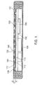
- Fig. 1 is a sectional view of a switch according to an embodiment of the present invention.
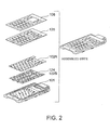
- Fig. 2 is an exploded perspective view of the switch, and
- Fig. 3 is a sectional view of a single switch unit.
- the switch according to the present invention has a plurality of protruding parts 112 and a plurality of supporting sections 113 both of which are formed on a surface of a thin metal sheet through press molding.
- a plurality of switch sections are formed by elastically deformable dome-shaped conductors 124 arranged such that the convex surfaces thereof are opposed to the protruding parts 112, a wiring sheet 102A covering the conductors 124, and switch buttons 125.
- At least two supporting sections 113 are provided around each protruding part 112, and the supporting sections 113 are arranged so that the conductor 124 of an elastic material can be accommodated between one supporting section 113 and another supporting section 113. That is, the horizontal distance between the supporting sections 113, 113' is larger than the width of the conductor 124 formed of an elastic member in both the longitudinal and lateral directions.
- a substrate 104 on which an electronic component 103 is mounted and which is equipped with wiring is arranged inside the case main body 101.
- Fig. 3 which is a sectional view of the switch section of Fig. 1
- the key sheet 129 is arranged on the wiring sheet 102A.
- the switch button 125 is fixed to the key sheet 129, and there is provided a top plate 106 which surrounds the switch buttons 125 and which is arranged on the key sheet 129.
- the top plate 106 has a size somewhat larger than the contour of the key sheet 129, and is arranged so as to cover the components below.
- the protruding parts 112 are protruding portions formed by performing press working on a metal sheet, and are used to perform click operation by denting the convex portions of the conductors 124.
- the supporting sections 113 are arranged around each switch button 125.
- the supporting sections function to suppress malfunction due to depression of other switch buttons 125 in the periphery.
- Another function of the supporting sections 113 is to maintain the flatness of the portion of the top plate 106 around the switch buttons 125 and to secure the rigidity thereof. For example, even when the switch buttons 125 are depressed and a finger crosses over each switch button 125 to an adjacent switch region, it is possible to keep such an adjacent switch region flat and to maintain a sense of the requisite rigidity.
- the switch sheet 102 is a composite sheet formed by stacking the wiring sheet 102A, the conductors 124, the cover sheet 102B, etc together.
- the switch buttons 125 are mounted on top of the switch sheet 102.
- the conductors 124 are held by the cover sheet 102B which partially or entirely exhibits adhesiveness, and are substantially arranged at the same positions as the wiring patterns 122A and 122B of the wiring sheet 102A such that the convex portions of the conductors 124 are directed toward the protruding parts 112. Further, the conductors 124 are held by the cover sheet 102B so that the positional relationship with the wiring patterns 122A and 122B and the conductors 124 is kept unmoved in the horizontal direction.
- a plurality of conductors 124 of elastic members are provided on the wiring sheet 102A to establish a switch function for each switch button 125.
- the elastic members for forming the conductors 124 may be elastically deformable and may be kept electrically conductive between the wiring patterns 122A and 112B on elastic deformation.
- the conductors 124 may be entirely formed of a conductor, or the conductors 124 may have electrically conductive portions partially formed on an elastic deformable base member to provide electrical conduction between the wiring patterns 122A and 122B.
- the conductors 124 may be provided by elastic members for keeping electrical conduction between the wiring patterns 122A and 122B when the switch buttons 125 are depressed to elastically deform the conductors 124.
- the wiring sheet 102A forming the switch sheet 102 is a flexible printed circuit (FPC) sheet, and has the wiring patterns (electrodes) 122A and 122B on the surface opposite to the surface where the switch buttons 125 are arranged.
- the wiring patterns 122A and 122B are electrically connected to the electronic component 103 on the substrate 104 of Fig. 1 .
- the wiring patterns 122A are formed around the wiring patterns 122B in an annular shape.
- the wiring patterns 122A may be partially cut out so as to form lead-out wiring patterns for guiding the wiring patterns 122B outside of the formation areas of the wiring patterns 122A.
- the wiring patterns 122B may not always be a wiring pattern but may be an electrode for providing conduction for an electric signal.
- the conductors 124 have the outer peripheral portions contacted with the wiring patterns 122A with the pressing force given from the cover sheet 102B. Thus, the conductors 124 are in contact with the wiring patterns 122A and, as a result, the conductors 124 and the wiring patterns 122A are electrically connected to each other.
- the distance between the wiring patterns 122B and the upper surfaces of the convex portions of the conductors 124 is approximately 0.2 mm and this distance is sufficiently smaller than the diameter of the wiring patterns 122A.
- the wiring sheet 102A and the cover sheet 102B are formed of elastic sheets.
- the wiring patterns 122A and 122B may partially use electrodes for wiring.
- the elastic body electrically connected to the wiring patterns 122A may be electrically connected to the wiring pattern 122B when the switch button 125 is depressed.
- the configurations, dimensions, and layout of the supporting sections 113 and the protruding parts 112 are described.
- a plate for providing the switch button 125 is in one-to-one correspondence with one switch function.
- the supporting sections 113 are arranged at the four corners of the switch button 125"'.
- the upper surfaces of the supporting sections 113 may be selected in configuration from circular, elliptical, and polygonal shapes and are shaped into the circular and elliptical configurations in this example.
- the end surfaces of the upper surfaces of the supporting sections 113 have rounded configurations of a predetermined curvature.
- the protruding parts 112 are of a circular shape, and their upper end surfaces are of a predetermined rounded configuration. Gaps are provided between the contours of the protruding parts 112 and the contours of the switch buttons 125 so that they may not overlap each other at least in one direction in plan view. In the example shown, the contours of the switch buttons 125 are formed to be larger than the contours of the protruding parts 112. As a result, the switch buttons 125 have portions not opposed to the protruding parts 112, that is, they have gaps. A reduction in gaps brings about deterioration of the feeling of click. Further, the gap degree is directly related to the interval between the switch buttons, and hence it has an influence on the design property.
- the dimensions and the layout of the supporting sections 113 and the protruding parts 112 are determined in consideration of the characteristics of the materials used and the design.
- the diameter and the height of the protruding parts 112 influence the click characteristic of the conductors 124.
- the diameter of the protruding parts 112 is preferably approximately 20% to 50% of the diameter of the conductors 124.
- each diameter ⁇ of the protruding parts 112 preferably falls within a range from 1.5 to 2.0 mm, and the height thereof preferably ranges from 0.2 to 0.3 mm.
- the height of the supporting sections 113 are set to a height somewhat higher than the height of the protruding parts 112.
- the area of the supporting sections 113 is too large as compared with the area of the periphery of the protruding parts 112, or when the supporting sections 113 are too close to the protruding parts 112, or when the difference in height between the supporting sections 113 and the protruding parts 112 is too large, a feeling of click may be deteriorated. Further, if the protruding parts 112 are higher than the supporting sections 113, malfunctions of the peripheral switch buttons and deflection of the peripheral portion will be caused to occur.
- the size, the thickness, the material, a laminated structure, and the like would be optimized about the members constituting the switch section 126, that is, in this construction, about the cover sheet 102B, the wiring sheet 102A, the conductors 124, the top cover 106, and the switch section 126.
- the layout and the dimensional relationship are exemplified in Fig. 6 .
- An example of the configuration, dimension, and layout of the protruding parts 112 and the supporting sections 113 is explained on the assumption that the outer diameter ⁇ of 4mm and an operational force of 1.3N of the single conductor 124 are determined by the specifications.
- the 2 switch button 125"' has a lateral width X0 of 9.5 mm, a longitudinal width Y0 of 5 mm, a lateral directional pitch PX of 12.5 mm, and a longitudinal directional pitch PY of 7.5 mm.
- the supporting sections 113 are arranged at four corners of the switch button 125. More specifically, there are arranged two columnar supporting sections 113 on the lower right-hand and left-hand sides of Fig. 6 , and two elliptical supporting sections 113' on the upper right-hand and left-hand sides thereof.
- the upper surface diameter X1 of the illustrated protruding part 112 is set to ⁇ 1.5 mm, and the upper surface diameter X2 of the illustrated supporting section 113 and the longitudinal width Y2 of the supporting section 113' are set to 1.35 mm. Further, the upper end surface dimension R2 of the supporting sections 113 is 0.3 mm, and the upper end surface dimension R1 of the protruding parts 112 is 0.3 mm. That is, they are shaped into a rounded configuration matched with the configuration formed when the switch buttons 125 and the conductors 124 are deflected.
- the horizontal distance (inner dimension) between the supporting sections 113, 113' is larger than the width of the conductors 124 formed of an elastic material in both the longitudinal and lateral directions. This serves as a factor of improving the click characteristic.
- the height Y2 of the circular supporting sections 113 and that of the elliptical supporting sections 113' are both 0.35 mm while the height of the protruding parts 112 is 0. 3mm, and the difference in height between the supporting sections 113 and the protruding parts 112 is equal to 0.05 mm.
- the height of the supporting sections 113' is the same as that of the supporting sections 113, and there is provided a laterally adjacent step Y4, whose dimension is 0.08 mm.
- the lateral gap X of the switch button 125 and the supporting sections 113 is approximately 0. 8 mm
- the longitudinal gap Y thereof is 0.6 mm.
- the feeling of click is greatly influenced by the gap X, the gap Y, the protruding part height Y1, the supporting section height Y2, the step Y3 of the difference in height between the protruding parts 112 and the supporting sections 113, and the configuration of the upper surfaces of the supporting sections 113.
- the above-mentioned dimensional relationship is effective to an example for providing a satisfactory feeling of click. Apart from this, an adjustment is also made on the kind and thickness of the constituent material, the gluing material, and the gluing area. Regarding the above-mentioned dimensional relationship, it is possible to obtain an optimum value through the design based on the arrangement of the switch buttons 125 and a combination of the material and thickness of each member. Thus, the above-mentioned values should not be construed restrictively.
- the above-mentioned structure is covered with a back casing 105 (in Fig. 1 ) so that the electronic component 103 and the substrate 104 may not be exposed to the exterior.
- the back casing 105 may be omitted.
- the switch operation is described.
- the wiring sheet 102 and the cover sheet 102B undergo elastic deformation, and the wiring patterns 122B are pushed down.
- the convex portions of the conductors 124 are pushed upwardly by the protruding parts 112, and are brought into contact with the wiring patterns 122B in the vertical direction.
- the wiring patterns 122A and 122B become electrically continuous with each other via the conductors 124, and information indicative of the depression of the switch is input to the electronic component 103 on the substrate through the circuit as represented by that shown in Fig. 6 .
- electrical conduction is accomplished by depression of the switch buttons, electrical contact may be performed between the wiring patterns 122A and the outer peripheries of the conductors and between the wiring patterns 122B and the inner peripheries of the conductors 124.
- Fig. 9 shows the effect obtained when the supporting sections of the present invention are arranged in a dotted form.
- the click rate is regarded as important, and as the value thereof becomes larger, the feeling of click at the time of clicking becomes clearer.
- the operational force of the single conductor 124 is 1.3 N
- the click rate ranges from 10 to 15%
- the operational force ranges from approximately 1.7 to 1.8 N in the conventional supporting section structure in which the supporting sections are arranged in a single plane.
- the click rate is improved to approximately 20%, and the operational force is reduced to approximately 1.5 N, thereby achieving an improvement in the feeling of click.
- the supporting sections 113 also function to suppress malfunction of the peripheral switch buttons 125. Further, it is also possible to maintain the requisite flatness of the portion of the top plate 106 around the switch buttons 125 and to secure the requisite rigidity.
- the case main body 101 accommodate the substrate 104 on which the electronic component 103 is mounted, but also functions as a base for supporting the pressing force for the switch buttons 125, receiving the force generated when the user depresses the switch buttons 125.
- the casing of the present invention is produced through press molding of a thin metal sheet using a mold, forming the case main body 101, the protruding parts 112, and the supporting sections 113 integrally.
- the metal sheet case main body 101 is used as the base of the switch section.
- the metal sheet casing may be installed in the mold, and filling with resin is effected, thereby performing integral molding within the mold.
- integral resin molding is performed on the portion corresponding to the outer periphery of the metal sheet casing.
- the configuration of the resin portion formed in the outer periphery serves to maintain the configuration for positioning the switch section and the inner components, and to complementarily strengthen the casing.
- thinning of mobile terminals brings about a tendency of reducing their components in thickness.
- the casing should have a function of protecting the inner electronic components without deformation of the casing itself.
- flow of the molten material becomes bad.
- magnesium or aluminum is used as a molding material like in a conventional method
- flow property of the material becomes poor and a mass production becomes difficult with a stable quality kept when the thin-walled portions of the protruding part of each lower portion are molded in a thickness of approximately 0.3 mm.
- a wall thickness of approximately 0.4 to 0.45 mm is the limit at the protruding part lower portions where the wall thickness is minimum.
- the casing is reduced in thickness, and the regions requiring rigidity and switch function are formed by a metal sheet while the regions requiring complicated configuration are formed by resin. According to this structure, it is possible to suppress a reduction in bending rigidity and torsional rigidity of the casing is suppressed, making it possible to prevent deformation and damage of the constituent components. Further, by integrally molding the protruding parts 112 and the supporting sections 113 with the case main body 101, it is possible to achieve thinning as compared with the case in which the protruding parts 112 or the supporting sections 113 are formed as separate components in the form of dedicated sheets.
- the casing structure of the present invention exhibits sufficient rigidity, and maintains a predetermined requisite configuration if an external force such as switch operation, etc. by the user is applied thereto. Further, due to the above-mentioned rigidity, deflection of the casing can be suppressed to a minimum at the time of switch depression, and hence it is possible to obtain a clear feeling of click. As described above, by integrally molding the protruding parts 112 and the supporting sections 113 through press molding of a thin metal sheet, thinning of the casing is possible.
- the deformation amount of the substrate 104 accommodated in the case main body 101 can be minimized, making it also possible to suppress separation of the solder of the electronic component 103 mounted on the substrate 104 and to suppress damage of the wiring.
- the protruding parts 112 and the supporting sections 113 are formed by press molding, whereby it is possible to generate a space on the side opposite to the protruding side, and heat generated by the electronic component 103 and the substrate 104 arranged inside the casing are heat-insulated by the air layer, suppressing an excessive increase in the temperature of the switch section surface touched by the user.
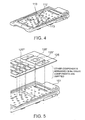
- Fig. 5 also shows a perspective view of the second embodiment of the present invention, in which the portion around the four-direction switch button is illustrated.
- the plate constituting the switch button is in one-to-one correspondence with a switch function.
- the second embodiment differs from the first embodiment in the arrangement of the support sections constituted when the plate of the switch button has a plurality of switch functions.
- the four-way switch button 125' shown in the figure has four switch functions assigned to the four sides of its rectangular configuration.
- One supporting section is provided for each of the right and left-hand side switch functions. In this case, two or more peripheral supporting sections are arranged for a single plate constituting the switch button.
- each switch button 125 there are arranged rectangular supporting sections 113 on the upper and lower, and right-hand and left-hand sides of each switch button 125. Further, the supporting sections 113 also serve as the supporting sections of the adjacent switch button 125. As a result, there is no need to arrange supporting sections in the region that becomes narrow due to the presence of the peripheral protruding parts 112 and supporting sections 113. In the press molding of a metal sheet, as more protruding objects exist in a small region, the moldability becomes poorer, resulting in deterioration in flatness and the dimensional precision of the protruding objects. In this way, it is possible to obtain the effect of suppressing deterioration in moldability and a feeling of click.
- the protruding parts 112 and the supporting sections 113 of some other material on the metal sheet.
- the heat insulation effect due to press molding and space formation is reduced, and the number of components increases.
- the complicated configuration in press molding is mitigated, which is advantageous in manufacturing from the viewpoint of attaining high precision in flatness.
- the casing includes a metal sheet and a resin portion constituting an exterior portion and being formed of a resin, the resin portion may be formed only when it is needed.
- the switch of the present invention may have a structure corresponding to the casing formed by a metal sheet.
- the present invention is applicable not only to a mobile phone but also to other mobile terminals such as a PDA and an electronic device such as a personal computer.
Landscapes
- Push-Button Switches (AREA)
Claims (15)
- Schalter, umfassend:eine Verdrahtungschicht (102A), die auf ihrer Oberfläche eine Verdrahtung aufweist;ein elastisches Element (124), das elektrisch leitend mit der Verdrahtung der Verdrahtungschicht (102A) verbunden ist; undeine Struktur (101), die mit einer Mehrzahl von Stützabschnitten (113) zum Stützen der Verdrahtungschicht (102A) ausgestattet ist,wobei die Mehrzahl der Stützabschnitte (113) so angeordnet ist, dass das elastische Element (124) zwischen den Stützabschnitten (113) aufgenommen ist, und wobei ein Abstand zwischen den Stützabschnitten (113) größer ist als eine Breite des elastischen Elements (124), dadurch gegenzeichnet, dass die Mehrzahl von Stützabschnitten (113) derart voneinander beabstandet ist, dass sie die Verdrahtungschicht (102A) an einer Mehrzahl von Positionen stützen, die voneinander beabstandet sind.
- Schalter nach Anspruch 1, wobei die Verdrahtungschicht (102A) eine Elektrode (122B) aufweist, und wobei die Elektrode (122B) derart angeordnet ist, dass sie zum Zeitpunkt der Verformung des elastischen Elements (124) in Kontakt mit dem elastischen Element (124) ist.
- Schalter nach Anspruch 1, ferner umfassend einen Raum (111), in dem das elastische Element (124) durch die Mehrzahl von Stützabschnitten (113) aufgenommen ist, und wobei ein vorstehendes Teil (112) auf der Struktur (101) gebildet ist, die den Raum (111) bildet.
- Schalter nach Anspruch 1, wobei das elastische Element (124) zwischen der Verdrahtungschicht (102A) und einer Deckschicht (102B) gehalten ist.
- Schalter nach Anspruch 1, ferner umfassend einen Schalterknopf (125), der auf einer Rückfläche der Verdrahtungschicht (1 02A) angeordnet ist.
- Schalter nach Anspruch 1, ferner umfassend eine obere Platte (100), die auf einer Rückflächenseite der Verdrahtungschicht (102A) vorgesehen ist und die Verdrahtungschicht (102A) bedeckt.
- Schalter nach Anspruch 1, wobei die Struktur ein Gehäuse ist, welches eine mit Harz gefüllte äußere Umfangsfläche aufweist.
- Schalter nach Anspruch 1, wobei das Gehäuse aus einem Schichtmetall gebildet ist.
- Elektronische Vorrichtung, umfassend den Schalter nach Anspruch 1.
- Schalter nach Anspruch 1, wobei die Struktur eine Mehrzahl von vorstehenden Teilen (112) umfasst, die jeweils von der Mehrzahl der Stützabschnitten (113) umgeben sind und die integral durch Druckformen zusammen mit den Stützabschnitten (113) gebildet sind.
- Schalter nach Anspruch 10, wobei die Stützabschnitte (113) höher als die vorstehenden Teile (112) sind.
- Schalter nach Anspruch 11, wobei die Stützabschnitte (113) und die vorstehenden Teile (112) durch eine Metallschicht gebildet sind.
- Schalter nach Anspruch 12, wobei die Metallschicht einen Gehäusehauptkörper bildet.
- Schalter nach einem der Ansprüche 10 bis 13, ferner umfassend Schalterknöpfe (125), die in einer eins-zu-eins-Entsprechung mit den jeweiligen vorstehenden Teilen (112) angeordnet sind;
wobei die Stützabschnitte (113) an Positionen vorgesehen sind, wo jeder Schalterknopf nicht in Kontakt mit den Stützabschnitten (113) gelangt, wenn er gedrückt wird. - Schalter nach Anspruch 1 bis 14, wobei die Stützabschnitte (113) Stützoberflächen mit kreisförmiger, elliptischer oder polygonaler Gestalt aufweisen.
Priority Applications (1)
| Application Number | Priority Date | Filing Date | Title |
|---|---|---|---|
| EP11177913A EP2388791A3 (de) | 2006-02-13 | 2007-02-13 | Schalter und elektronisches Gerät damit |
Applications Claiming Priority (2)
| Application Number | Priority Date | Filing Date | Title |
|---|---|---|---|
| JP2006035778 | 2006-02-13 | ||
| PCT/JP2007/052903 WO2007094483A1 (ja) | 2006-02-13 | 2007-02-13 | スイッチおよびこれを有する電子機器 |
Related Child Applications (1)
| Application Number | Title | Priority Date | Filing Date |
|---|---|---|---|
| EP11177913.8 Division-Into | 2011-08-18 |
Publications (4)
| Publication Number | Publication Date |
|---|---|
| EP1986207A1 EP1986207A1 (de) | 2008-10-29 |
| EP1986207A4 EP1986207A4 (de) | 2010-07-21 |
| EP1986207B1 EP1986207B1 (de) | 2011-09-14 |
| EP1986207B9 true EP1986207B9 (de) | 2012-02-15 |
Family
ID=38371657
Family Applications (2)
| Application Number | Title | Priority Date | Filing Date |
|---|---|---|---|
| EP07714430A Not-in-force EP1986207B9 (de) | 2006-02-13 | 2007-02-13 | Schalter und elektronisches gerät damit |
| EP11177913A Withdrawn EP2388791A3 (de) | 2006-02-13 | 2007-02-13 | Schalter und elektronisches Gerät damit |
Family Applications After (1)
| Application Number | Title | Priority Date | Filing Date |
|---|---|---|---|
| EP11177913A Withdrawn EP2388791A3 (de) | 2006-02-13 | 2007-02-13 | Schalter und elektronisches Gerät damit |
Country Status (5)
| Country | Link |
|---|---|
| US (1) | US7619176B2 (de) |
| EP (2) | EP1986207B9 (de) |
| JP (1) | JP5177423B2 (de) |
| CN (1) | CN101385107B (de) |
| WO (1) | WO2007094483A1 (de) |
Families Citing this family (7)
| Publication number | Priority date | Publication date | Assignee | Title |
|---|---|---|---|---|
| JP4359812B2 (ja) * | 2002-07-08 | 2009-11-11 | 日本電気株式会社 | スイッチ一体型筐体およびこれを有する電子機器 |
| JP5177424B2 (ja) * | 2006-02-13 | 2013-04-03 | 日本電気株式会社 | 照光式スイッチおよびこれを有する電子機器 |
| US20110011715A1 (en) * | 2008-03-06 | 2011-01-20 | Nec Corporation | Switch mechanism and electronic device |
| US7902474B2 (en) | 2008-05-01 | 2011-03-08 | Apple Inc. | Button assembly with inverted dome switch |
| SE536533C2 (sv) | 2012-04-30 | 2014-02-04 | Fmt Int Trade Ab | Förfarande för att identifiera ett flygplan i samband med parkering av flygplanet vid ett stand |
| US10743620B2 (en) | 2015-05-28 | 2020-08-18 | Nike, Inc. | Automated tensioning system for an article of footwear |
| US11202484B2 (en) * | 2016-03-15 | 2021-12-21 | Nike, Inc. | Standoff unit for a control device in an article of footwear |
Family Cites Families (12)
| Publication number | Priority date | Publication date | Assignee | Title |
|---|---|---|---|---|
| CH591724A5 (de) * | 1975-05-23 | 1977-09-30 | Suisse Horlogerie | |
| US4086451A (en) * | 1976-12-06 | 1978-04-25 | Texas Instruments Incorporated | Keyboard apparatus |
| US4245138A (en) * | 1978-11-17 | 1981-01-13 | Rogers Corporation | Tactile element and keyboard including the tactile element |
| DE8610553U1 (de) * | 1986-04-17 | 1986-05-28 | Wilhelm Ruf Kg, 8000 Muenchen | Membrantastatur |
| JPH01221824A (ja) | 1988-02-29 | 1989-09-05 | Matsushita Electric Ind Co Ltd | 押しボタンスイッチ |
| FR2659459B1 (fr) * | 1990-03-08 | 1993-11-26 | Sextant Avionique | Touche a effet tactile et clavier utilisant cette touche. |
| JPH0935571A (ja) * | 1995-07-14 | 1997-02-07 | Matsushita Electric Ind Co Ltd | 照光式スイッチユニット |
| US6018132A (en) * | 1999-08-27 | 2000-01-25 | Hon Hai Precision Ind. Co., Ltd. | Horizontal tact switch |
| FI108582B (fi) * | 2000-05-02 | 2002-02-15 | Nokia Corp | Näppäimistön valaisujärjestely, joka mahdollistaa näppäinten muuttuvan ja yksilöllisen valaisemisen, sekä menetelmä sen käyttämiseksi |
| JP4359812B2 (ja) * | 2002-07-08 | 2009-11-11 | 日本電気株式会社 | スイッチ一体型筐体およびこれを有する電子機器 |
| US6639165B1 (en) * | 2002-10-28 | 2003-10-28 | Delphi Technologies, Inc. | Multiple contact fluid pressure switch |
| KR200358531Y1 (ko) * | 2004-05-01 | 2004-08-11 | 주식회사 케이비에프 | El 메탈 돔 키패드 |
-
2007
- 2007-02-13 EP EP07714430A patent/EP1986207B9/de not_active Not-in-force
- 2007-02-13 US US12/279,163 patent/US7619176B2/en active Active
- 2007-02-13 CN CN200780005360.9A patent/CN101385107B/zh not_active Expired - Fee Related
- 2007-02-13 EP EP11177913A patent/EP2388791A3/de not_active Withdrawn
- 2007-02-13 JP JP2008500580A patent/JP5177423B2/ja not_active Expired - Fee Related
- 2007-02-13 WO PCT/JP2007/052903 patent/WO2007094483A1/ja not_active Ceased
Also Published As
| Publication number | Publication date |
|---|---|
| EP2388791A2 (de) | 2011-11-23 |
| EP2388791A3 (de) | 2012-07-04 |
| CN101385107A (zh) | 2009-03-11 |
| WO2007094483A1 (ja) | 2007-08-23 |
| US7619176B2 (en) | 2009-11-17 |
| CN101385107B (zh) | 2013-03-27 |
| EP1986207B1 (de) | 2011-09-14 |
| JPWO2007094483A1 (ja) | 2009-07-09 |
| EP1986207A4 (de) | 2010-07-21 |
| US20090026057A1 (en) | 2009-01-29 |
| JP5177423B2 (ja) | 2013-04-03 |
| EP1986207A1 (de) | 2008-10-29 |
Similar Documents
| Publication | Publication Date | Title |
|---|---|---|
| EP1986207B1 (de) | Schalter und elektronisches gerät damit | |
| CN100483588C (zh) | 开关一体型壳体和具有该壳体的电子设备 | |
| US7429707B2 (en) | Push switch | |
| EP3196910B1 (de) | Drucktastenschalter | |
| US20050199475A1 (en) | Two-step switch | |
| US20080296141A1 (en) | Key Input Apparatus and Electronic Device | |
| US20100230267A1 (en) | Push switch | |
| KR100743139B1 (ko) | 5방향 키 조작 장치 | |
| JP5160362B2 (ja) | ポインティングデバイス | |
| JP4514366B2 (ja) | 押釦スイッチ用部材 | |
| JP4252509B2 (ja) | キーボード装置 | |
| KR100596302B1 (ko) | 이동통신단말기의 키패드 | |
| JP2006211581A (ja) | 電子機器のサイドキースィッチ | |
| JP4784630B2 (ja) | スイッチ一体型筐体およびこれを有する電子機器 | |
| JPH08306261A (ja) | 表面実装型タクトスイッチ及びその製造方法 | |
| JP2010192279A (ja) | 可動接点付きシート | |
| JP2012151079A (ja) | スイッチ | |
| JP2008131442A (ja) | 携帯無線機及びその製造方法 | |
| JPH07220573A (ja) | 操作ボタン構造 | |
| JP2004311156A (ja) | 多方向操作スイッチシートおよび多方向操作スイッチ | |
| JP2013062208A (ja) | プッシュオンスイッチ |
Legal Events
| Date | Code | Title | Description |
|---|---|---|---|
| PUAI | Public reference made under article 153(3) epc to a published international application that has entered the european phase |
Free format text: ORIGINAL CODE: 0009012 |
|
| 17P | Request for examination filed |
Effective date: 20080826 |
|
| AK | Designated contracting states |
Kind code of ref document: A1 Designated state(s): DE FR GB |
|
| RBV | Designated contracting states (corrected) |
Designated state(s): DE FR GB |
|
| A4 | Supplementary search report drawn up and despatched |
Effective date: 20100623 |
|
| 17Q | First examination report despatched |
Effective date: 20100713 |
|
| GRAP | Despatch of communication of intention to grant a patent |
Free format text: ORIGINAL CODE: EPIDOSNIGR1 |
|
| RIC1 | Information provided on ipc code assigned before grant |
Ipc: H01H 13/48 20060101ALI20110309BHEP Ipc: H01H 13/02 20060101AFI20110309BHEP Ipc: H01H 13/702 20060101ALI20110309BHEP |
|
| GRAS | Grant fee paid |
Free format text: ORIGINAL CODE: EPIDOSNIGR3 |
|
| GRAA | (expected) grant |
Free format text: ORIGINAL CODE: 0009210 |
|
| AK | Designated contracting states |
Kind code of ref document: B1 Designated state(s): DE FR GB |
|
| REG | Reference to a national code |
Ref country code: GB Ref legal event code: FG4D |
|
| REG | Reference to a national code |
Ref country code: DE Ref legal event code: R096 Ref document number: 602007017174 Country of ref document: DE Effective date: 20111117 |
|
| PLBE | No opposition filed within time limit |
Free format text: ORIGINAL CODE: 0009261 |
|
| STAA | Information on the status of an ep patent application or granted ep patent |
Free format text: STATUS: NO OPPOSITION FILED WITHIN TIME LIMIT |
|
| 26N | No opposition filed |
Effective date: 20120615 |
|
| REG | Reference to a national code |
Ref country code: DE Ref legal event code: R097 Ref document number: 602007017174 Country of ref document: DE Effective date: 20120615 |
|
| REG | Reference to a national code |
Ref country code: GB Ref legal event code: 732E Free format text: REGISTERED BETWEEN 20141023 AND 20141029 |
|
| REG | Reference to a national code |
Ref country code: FR Ref legal event code: TP Owner name: LENOVO INNOVATIONS LIMITED (HONG KONG), HK Effective date: 20141119 |
|
| REG | Reference to a national code |
Ref country code: FR Ref legal event code: PLFP Year of fee payment: 10 |
|
| PGFP | Annual fee paid to national office [announced via postgrant information from national office to epo] |
Ref country code: FR Payment date: 20160108 Year of fee payment: 10 |
|
| REG | Reference to a national code |
Ref country code: FR Ref legal event code: ST Effective date: 20171031 |
|
| PG25 | Lapsed in a contracting state [announced via postgrant information from national office to epo] |
Ref country code: FR Free format text: LAPSE BECAUSE OF NON-PAYMENT OF DUE FEES Effective date: 20170228 |
|
| REG | Reference to a national code |
Ref country code: DE Ref legal event code: R081 Ref document number: 602007017174 Country of ref document: DE Owner name: LENOVO INNOVATIONS LIMITED, HK Free format text: FORMER OWNER: NEC CORPORATION, TOKIO/TOKYO, JP |
|
| PGFP | Annual fee paid to national office [announced via postgrant information from national office to epo] |
Ref country code: DE Payment date: 20190228 Year of fee payment: 13 Ref country code: GB Payment date: 20190227 Year of fee payment: 13 |
|
| REG | Reference to a national code |
Ref country code: DE Ref legal event code: R119 Ref document number: 602007017174 Country of ref document: DE |
|
| GBPC | Gb: european patent ceased through non-payment of renewal fee |
Effective date: 20200213 |
|
| PG25 | Lapsed in a contracting state [announced via postgrant information from national office to epo] |
Ref country code: DE Free format text: LAPSE BECAUSE OF NON-PAYMENT OF DUE FEES Effective date: 20200901 Ref country code: GB Free format text: LAPSE BECAUSE OF NON-PAYMENT OF DUE FEES Effective date: 20200213 |