EP1987226B1 - Dispositif d'injection de fluide - Google Patents
Dispositif d'injection de fluide Download PDFInfo
- Publication number
- EP1987226B1 EP1987226B1 EP07709222.9A EP07709222A EP1987226B1 EP 1987226 B1 EP1987226 B1 EP 1987226B1 EP 07709222 A EP07709222 A EP 07709222A EP 1987226 B1 EP1987226 B1 EP 1987226B1
- Authority
- EP
- European Patent Office
- Prior art keywords
- internal body
- outer housing
- internal
- fluid
- valve
- Prior art date
- Legal status (The legal status is an assumption and is not a legal conclusion. Google has not performed a legal analysis and makes no representation as to the accuracy of the status listed.)
- Active
Links
Images

Classifications
-
- E—FIXED CONSTRUCTIONS
- E21—EARTH OR ROCK DRILLING; MINING
- E21B—EARTH OR ROCK DRILLING; OBTAINING OIL, GAS, WATER, SOLUBLE OR MELTABLE MATERIALS OR A SLURRY OF MINERALS FROM WELLS
- E21B43/00—Methods or apparatus for obtaining oil, gas, water, soluble or meltable materials or a slurry of minerals from wells
- E21B43/01—Methods or apparatus for obtaining oil, gas, water, soluble or meltable materials or a slurry of minerals from wells specially adapted for obtaining from underwater installations
- E21B43/013—Connecting a production flow line to an underwater well head
-
- E—FIXED CONSTRUCTIONS
- E21—EARTH OR ROCK DRILLING; MINING
- E21B—EARTH OR ROCK DRILLING; OBTAINING OIL, GAS, WATER, SOLUBLE OR MELTABLE MATERIALS OR A SLURRY OF MINERALS FROM WELLS
- E21B34/00—Valve arrangements for boreholes or wells
- E21B34/02—Valve arrangements for boreholes or wells in well heads
-
- E—FIXED CONSTRUCTIONS
- E21—EARTH OR ROCK DRILLING; MINING
- E21B—EARTH OR ROCK DRILLING; OBTAINING OIL, GAS, WATER, SOLUBLE OR MELTABLE MATERIALS OR A SLURRY OF MINERALS FROM WELLS
- E21B43/00—Methods or apparatus for obtaining oil, gas, water, soluble or meltable materials or a slurry of minerals from wells
- E21B43/12—Methods or apparatus for controlling the flow of the obtained fluid to or in wells
- E21B43/121—Lifting well fluids
- E21B43/122—Gas lift
- E21B43/123—Gas lift valves
-
- Y—GENERAL TAGGING OF NEW TECHNOLOGICAL DEVELOPMENTS; GENERAL TAGGING OF CROSS-SECTIONAL TECHNOLOGIES SPANNING OVER SEVERAL SECTIONS OF THE IPC; TECHNICAL SUBJECTS COVERED BY FORMER USPC CROSS-REFERENCE ART COLLECTIONS [XRACs] AND DIGESTS
- Y10—TECHNICAL SUBJECTS COVERED BY FORMER USPC
- Y10T—TECHNICAL SUBJECTS COVERED BY FORMER US CLASSIFICATION
- Y10T137/00—Fluid handling
- Y10T137/7722—Line condition change responsive valves
- Y10T137/7837—Direct response valves [i.e., check valve type]
- Y10T137/7904—Reciprocating valves
- Y10T137/7922—Spring biased
- Y10T137/7925—Piston-type valves
Definitions
- the present invention regards a device for injection of fluid in a well bore, typically an offshore well bore, typically installed on Christmas trees or wellheads, for petroleum production and gas injection/ gas lift system.
- US 6.196.259 describes a fluid valve for controlling the flow of a fluid from an upstream region to a downstream region.
- the fluid valve comprises a housing having a fluid exit, a shut-off member and a fluid entry member movably disposed within the housing.
- An aim with the present invention is to minimize and possibly alleviate these problems. It is also an aim to provide a device with a true metal to metal sealing of the device.
- Metal to metal seal in a preferred embodiment is understood to be a single seal between two metallic surfaces without any secondary seal, soft seal or a combination of such. It is also an aim to provide a device with a reduced erosion rate of the sealing surface.
- Another aim is to provide a device with an increased flow area compared with similar known valves.
- the present invention regards a device designed for injection and stimulation of fluids in a well bore, typically an offshore well bore for petroleum production and gas injection / gas lift system for fluid injection.
- the device may also be used for chemical injection of other constituents such as well stimulation fluids, cutting injection, water injection etc.
- This device which is used to create a one-way seal within a Christmas tree or a wellhead flange outlet, seals off within a dedicated spool piece, which spool piece is made up between the wellhead and a manual gate valve.
- a hydraulic port in the spool piece allows hydraulic pressure to be routed to the device for its operation.
- the device comprises an outer hollow housing with an internal body moveable within the outer housing.
- the internal body comprises an internal bore which in a first closed position is closed with a metal to metal seal system between the outer housing and the internal body.
- the movement of the internal body may be operated by pressure differential across the internal body.
- This pressure differential may be a fluid pressure operating on surfaces of the internal body, which surfaces may be exposed to different fluids.
- These fluids may be well fluids on one or more surfaces for operating the device or injections fluid on one surface and well fluid on another surface or combinations.
- the pressure differential across the internal body is assisted by at least one predetermined pressure balanced elastic element to open and close the device.
- the elastic element comprise a spring element enclosed in a chamber, which chamber is filled with a fluid separate from both well and injection fluid.
- the internal body comprises at least one slot between the bore and the outside of the internal body. These slots in the internal body are leading directly to the outside of the outer housing in an open position of the device, and are positioned within the outer housing in a closed position of the device. The part of the internal body comprising the slots are moved relative the outer housing from a position within the outer housing in a closed state of the valve to a position at least partly outside the housing in an open state of the valve.
- the slots may be longitudinal and distributed on the circumference of the inner body.
- the distribution may be evenly around the circumference of the internal body.
- the form of the slot may be even or odd around the circumference of the body.
- the slots may be longitudinal with a main longitudinal direction mainly parallel with a longitudinal axis of the internal body.
- the slots may be longitudinal with a main direction at an angle relative to the longitudinal axis of the internal body or form a part spiral shape around a longitudinal axis, or formed with another shape.
- the slots around the internal body may also be of different shapes, whereof some may be larger than other slots.
- the slots in the internal body may be made beveled and angled from an internal surface to an outer surface of the internal body in order to obtain stream line flow.
- the seal system comprises a valve seat in the outer housing and a valve element sealing surface on the internal body.
- valve seat and the valve element sealing surface in an open or partially open position are positioned on opposite sides of a slot seen in a longitudinal direction of the device. This gives that the slots forming the flow path of the injection fluid are positioned between the valve seat and the valve element sealing surface in an open position of the device.
- valve seat may comprise a low pressure guide to obtain optimal guiding sealing engagement as a secondary embodiment.
- the internal body comprises a stop surface which in a fully open position of the device is abutting against a corresponding surface in the outer housing.
- the internal body and outer housing may comprise corresponding parts of at least one guiding element predefining a travel between a closed and an open position of the device.
- the internal body may comprise at least one fluid balanced wing(s) or baffle(s) and or added slots in the internal surface of the internal body exposed to the injection fluid to guide the internal body in a predetermined travel between open and closed position of the device. This predefining travel may be linear, rotational and or a combination of this.
- the device further may comprise at least one element for overriding and or controlling the open and or closed position of the device.
- the outer housing may comprise a wiper element positioned to abut against and clean the sealing surface during closing of the device. This is favorable in the case when the injection fluid contains particles prone to be attached to the sealing surfaces.
- the elastic element may comprise a spring element enclosed in a chamber, which chamber is filled with a fluid separate from both well and injection fluid
- the outer housing and or the internal body may comprise several separable elements connected by for instance threaded joints. This gives the possibility to replace for instance the element of the outer housing comprising the valve seat without having to replace the whole housing.
- the injection device of the present invention may also be positioned in a hydraulic spool piece in relation to a Christmas tree as mentioned above.
- the spool piece may be formed as a flange and comprise a main bore, in which main bore the injection device may be positioned.
- the side bores may be adapted to be in communication with at least one opening in the outer housing of the injection device, in order to add hydraulic fluid for operation of the device.
- the device may also comprise a pretension means to set the device, i.e. the valve to a given position when hydraulic pressure is not present through the opening, for instance a closed position.
- the pretension device may be an elastic element such as spring or other pretension means.
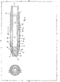
- the device comprises an outer housing 1, which is formed from several elements, with an internal body 2 movable within the outer housing 1 between two positions, an open position shown to the left in the figure and a closed position shown in the right half of the figure.
- the internal body 2 is movable in the longitudinal direction of the internal body 2 and outer housing 1.
- the outer housing 1 comprises an injection fluid inlet at one end of the outer housing 1 connected to a source of injection fluid (not shown).
- the injection fluid is transferred through an internal void of the outer housing 1 to an internal bore 3 of the internal body 2.
- the bore 3 stretches in the longitudinal direction of the internal body 2.
- the injection fluid will thereafter in an open position of the valve flow through slots 4 leading from the internal bore 3 to the outside of the internal body 2, and the outside of the outer housing 1.
- a surface 9 of the slots 4 between an internal to an external side of the internal body 2 may be angled with angles other than 90 degrees with a longitudinal axis of the device.
- the surfaces 9 may also be formed with varying angles dependent on where around the slot 4, the part of the surfaces 9 it is.
- the valve shown also comprises an elastic element 6 arranged between a shoulder of the outer housing 1 and a shoulder of the internal body 2, biasing the internal body 2 to a closed position of the valve.
- an elastic element 6 arranged between a shoulder of the outer housing 1 and a shoulder of the internal body 2, biasing the internal body 2 to a closed position of the valve.
- the internal body 2 comprises an annular, valve element sealing surface 11, with a mainly conical shaped surface.
- This surface 11 is arranged close to an end of the internal body 2 with the end of the conical shaped surface 11 with the larger diameter, furthest away from the slots 4 of the internal body 2.
- the slots 4 are arranged close to an end of the internal body 2, and the surface 11 closer to the same end of the internal body 2.
- the sealing surface 11 of the internal body cooperates with a valve seat 10 arranged in the outer housing 1.
- the valve seat 10 in the outer housing 1 is arranged on the relative speaking other side of the slot 4, when these are in an open position, compared with the sealing surface 11 of the internal body 2, seen in a longitudinal direction of the device.
- the internal body 2 In a closed position, the internal body 2 is moved relative to the outer housing 1 so that the sealing surface 11 is abutting the valve seat 10, giving a sealed, metal to metal seal for the valve. In this closed position the slots 4 of the internal body 2 will be positioned within the valve device.
- a wiper element 50 at the end of the outer housing.
- This wiper element will when the valve is closing abut against the valve element sealing surface 11, scraping off any attached particles and other foreign element from the sealing surface 11 before it comes in contact with the valve seat 10 for sealing engagement between the surface 11 and the valve seat 10.
- the elastic element 6, in the form of a spring is arranged in a closed chamber 52, with an opening 53 between this chamber 52 and a second chamber 54 which works as a storage chamber for fluid within chamber 52 when the elastic element 6 becomes compressed.
- the two chambers 52, 54 are separated from each other by an internal flange 51 of the outer housing 1, giving only a small passage 53 for the transferal of fluid between the chamber 52, 54, thereby also regulating the movement of the inner body 2 relative the outer body 1.
- the form of the closed chambers 52, 54 around the elastic element, keeps any foreign particles which may affect the performance of the elastic element 6, away from the elastic element 6.
- a second embodiment of the device comprising an outer housing 1 and an internal body 2 movable within the outer housing 1.
- the outer housing 1 has an inlet 7 for the fluid entering the valve device, and there may in relation to this inlet also be positioned an orifice 8 to regulate the flow through the device, to for instance give the flow a rotating flow pattern.
- the outer housing 1 comprises a first part 1A and a second part 1B comprising the valve seat surface 10, which two parts 1A, 1B are connected by a threaded connection 1C.
- the outer housings second part 1B also comprises a stop surface 20.
- an aerating opening 56 in the outer housing to prevent any trapped fluid between the internal body 2 and the outer housing 1 from stopping the movement between the internal body 2 and the outer housing 1, this opening 56 may also be connected to a source of hydraulic fluid to operate the device between a closed and an open position.
- this opening 56 may also be connected to a source of hydraulic fluid to operate the device between a closed and an open position.
- the internal body 2 comprises in this embodiment a first part 26 and a second part 27, connected by a threaded connection 28.
- the first part 26 comprises an internal bore 3 connected with the inlet 7 of the outer housing 1, so that the inlet 7 leads directly to the internal bore 3 without any deviation of the flow of fluid through the device other than possibly passing an orifice 8, to give the flow of fluid through the valve device a most direct route with reduced pressure loss.
- the first part 26 further comprises an aerating opening 55, connecting the internal bore 3 with an chamber 52 formed between the outer housing and the internal body and the stop surface 30 of the outer housing and a stop surface 21 formed in the outer wall of the internal body, limiting the movement of the internal body 2 relative the outer housing in the open state of the valve.
- the first part 26 of the internal body 2 comprises also slots 4 running from the internal bore and radially outwards through the wall of the internal body 2.
- the slots 4 in this embodiment has a more elliptic form and the slot surface 9 formed in the wall of the internal body are formed at an angle different then 90 degrees with a longitudinal axis of the internal body, thereby directing the flow of fluid out of the device.
- the second part 27 of the internal body 2 comprises the sealing surface 11 for abutment against the valve seat 10 arranged on the outer housing 1.
- the sealing surface 11 forms an end of the second part 27 adjacent a section of the first part 26 of the internal body, and in between there is positioned additional sealing element 19, kept in place by the connection of the first 26 and second part 27 of the internal body 2.
- This sealing element 19 will also form a part of the sealing surface as it in a closed position of the valve device partly will abut the valve seat 10 of the outer housing 1.
- the internal end surface 18 of the internal bore 3 in the internal body 2, close to the slots 4 is in this embodiment countersunk.
- the similar surface is a flat surface. This internal end surface will form part of a pressure surface regulating the position of the valve device as a response to a pressure differential across the valve device.
- an outer housing or internal body may be formed in one unit or be comprised of several connected elements, and that the inlets have to be connected to a source of the fluid to be injected, that there should be appropriate attachment devices for attaching the valve within a process fluid stream and inside a hydraulic flange, and that there of course will be arranged for instance sealing element between several elements as a standard.
- an outer housing or internal body may be formed in one unit or be comprised of several connected elements, and that the inlets have to be connected to a source of the fluid to be injected, that there should be appropriate attachment devices for attaching the valve within a process fluid stream and inside a hydraulic flange, and that there of course will be arranged for instance sealing element between several elements as a standard.
Landscapes
- Geology (AREA)
- Life Sciences & Earth Sciences (AREA)
- Engineering & Computer Science (AREA)
- Mining & Mineral Resources (AREA)
- Environmental & Geological Engineering (AREA)
- Fluid Mechanics (AREA)
- Physics & Mathematics (AREA)
- General Life Sciences & Earth Sciences (AREA)
- Geochemistry & Mineralogy (AREA)
- Lift Valve (AREA)
- Jet Pumps And Other Pumps (AREA)
- Check Valves (AREA)
- Electrical Discharge Machining, Electrochemical Machining, And Combined Machining (AREA)
- Nozzles (AREA)
Claims (10)
- Dispositif d'injection et de stimulation de fluides dans un fluide de traitement, typiquement un puits de forage en mer, typiquement installé sur des arbres de Noël ou des têtes de puits, pour la production pétrolière et un système d'injection gazeuse / d'allégement au gaz, dans lequel le dispositif comprend un boîtier creux extérieur (1) et un corps intérieur (2) mobile dans le boîtier extérieur (1), comprenant un alésage intérieur (3), qui, dans une position fermée, est fermé avec un système d'étanchéité (10, 11) entre le boîtier extérieur (1) et le corps intérieur (2), lequel corps intérieur (2) est actionné par un différentiel de pression à travers le corps intérieur (2), dans lequel le corps intérieur (2) comprend au moins une fente (4) formant des sorties de l'alésage intérieur (3), qui dans une position ouverte du dispositif est positionnée au moins partiellement à l'extérieur du boîtier extérieur (1) débouchant sur un fluide environnant, caractérisé en ce que le dispositif comprend en outre une première chambre fermée (52) étant remplie d'un fluide séparé à la fois du puits et du fluide d'injection et une ouverture (53) entre cette chambre fermée (52) et une deuxième chambre (54), lesdites première et deuxième chambres étant séparées l'une de l'autre par une bride intérieure (51) du boîtier extérieur (1), et dans laquelle première chambre (52) un élément élastique prédéterminé à pression équilibrée (6) comprenant un élément de ressort est enfermé, dans lequel le différentiel de pression à travers le corps intérieur (2) est assisté par l'élément élastique prédéterminé à pression équilibrée (6) pour ouvrir et fermer le dispositif.
- Dispositif selon la revendication 1,
caractérisé en ce que les fentes (4) sont longitudinales et réparties sur la circonférence du corps intérieur (2). - Dispositif selon la revendication 2,
caractérisé en ce que les fentes dans le corps intérieur (2) sont biseautées et inclinées d'une surface intérieure à une surface extérieure du corps intérieur (2) pour obtenir un écoulement de ligne de flux prédéterminé. - Dispositif selon la revendication 2,
caractérisé en ce que les fentes longitudinales dans le corps intérieur (2) sont parallèles à une direction longitudinale du dispositif ou torsadées ou courbées autour de l'axe longitudinal. - Dispositif selon la revendication 1,
caractérisé en ce que le système d'étanchéité comprend un siège de soupape (10) dans le boîtier extérieur (1) et une surface d'étanchéité de l'élément de soupape (11) sur le corps intérieur (2). - Dispositif selon la revendication 5,
caractérisé en ce que le siège de soupape (10) et la surface d'étanchéité de l'élément de soupape (11) dans une position ouverte ou partiellement ouverte sont positionnés sur des côtés opposés d'une fente (4) vu dans une direction longitudinale du dispositif. - Dispositif selon la revendication 1,
caractérisé en ce que le dispositif comprend en outre des éléments d'annulation et / ou de commande de la position ouverte et / ou fermée du dispositif. - Dispositif selon la revendication 1, caractérisé en ce que le boîtier extérieur (1) comprend une ouverture traversante (56) pour permettre l'ajout de fluide hydraulique au dispositif pour le fonctionnement entre la position ouverte et fermée du dispositif.
- Dispositif selon la revendication 5, caractérisé en ce que le boîtier extérieur (1) comprend un élément d'essuyage (50) positionné pour venir en butée contre et nettoyer la surface d'étanchéité (11) lors de la fermeture du dispositif.
- Dispositif selon la revendication 5, caractérisé en ce que la surface d'étanchéité (11) dans une position ouverte du dispositif est positionnée à l'extérieur de l'extrémité extérieure du boîtier extérieur (1).
Applications Claiming Priority (2)
| Application Number | Priority Date | Filing Date | Title |
|---|---|---|---|
| NO20060610A NO327543B1 (no) | 2006-02-07 | 2006-02-07 | Fluidinjeksjonsanordning |
| PCT/NO2007/000039 WO2007091897A2 (fr) | 2006-02-07 | 2007-02-07 | dispositif d'injection de fluide |
Publications (2)
| Publication Number | Publication Date |
|---|---|
| EP1987226A2 EP1987226A2 (fr) | 2008-11-05 |
| EP1987226B1 true EP1987226B1 (fr) | 2020-04-22 |
Family
ID=38017015
Family Applications (1)
| Application Number | Title | Priority Date | Filing Date |
|---|---|---|---|
| EP07709222.9A Active EP1987226B1 (fr) | 2006-02-07 | 2007-02-07 | Dispositif d'injection de fluide |
Country Status (8)
| Country | Link |
|---|---|
| US (2) | US8186440B2 (fr) |
| EP (1) | EP1987226B1 (fr) |
| BR (1) | BRPI0707250B1 (fr) |
| CA (1) | CA2641401C (fr) |
| DK (2) | DK1987226T3 (fr) |
| ES (2) | ES2991850T3 (fr) |
| NO (2) | NO327543B1 (fr) |
| WO (1) | WO2007091897A2 (fr) |
Families Citing this family (23)
| Publication number | Priority date | Publication date | Assignee | Title |
|---|---|---|---|---|
| EP4219891B1 (fr) * | 2006-02-07 | 2024-06-26 | Petroleum Technology Company AS | Dispositif d'injection de fluide |
| NO327543B1 (no) * | 2006-02-07 | 2009-08-10 | Petroleum Technology Co As | Fluidinjeksjonsanordning |
| NO327545B1 (no) * | 2007-08-07 | 2009-08-10 | Petroleum Technology Company A | Anordning for injeksjon av fluider |
| EP2729658B1 (fr) * | 2011-07-06 | 2017-09-27 | Shell Internationale Research Maatschappij B.V. | Système et procédé pour injecter un liquide de traitement dans un puits de forage et soupape d'injection de liquide de traitement |
| US20130025358A1 (en) * | 2011-07-26 | 2013-01-31 | Baker Hughes Incorporated | Deployment Mechanism for Well Logging Devices |
| US8950499B2 (en) * | 2011-07-26 | 2015-02-10 | Chevron U.S.A. Inc. | Pipe-in-pipe apparatus, and methods and systems |
| CN103930647B (zh) * | 2011-11-08 | 2017-11-17 | 国际壳牌研究有限公司 | 用于烃井的阀,设置有该阀的烃井以及该阀的应用 |
| EP2815060A1 (fr) | 2012-02-14 | 2014-12-24 | Shell Internationale Research Maatschappij B.V. | Procédé de production d'hydrocarbure gazeux d'un puits de forage et ensemble vanne |
| GB201202581D0 (en) | 2012-02-15 | 2012-03-28 | Dashstream Ltd | Method and apparatus for oil and gas operations |
| AU2013254436B2 (en) | 2012-04-26 | 2017-10-12 | Enpro Subsea Limited | Oilfield apparatus and methods of use |
| EP2841683A2 (fr) * | 2012-04-26 | 2015-03-04 | Ian Donald | Appareil pour champ de pétrole et procédés d'utilisation |
| US10018022B2 (en) | 2012-04-27 | 2018-07-10 | Tejas Research & Engineering, Llc | Method and apparatus for injecting fluid into spaced injection zones in an oil/gas well |
| US10704361B2 (en) | 2012-04-27 | 2020-07-07 | Tejas Research & Engineering, Llc | Method and apparatus for injecting fluid into spaced injection zones in an oil/gas well |
| US9523260B2 (en) | 2012-04-27 | 2016-12-20 | Tejas Research & Engineering, Llc | Dual barrier injection valve |
| US9334709B2 (en) * | 2012-04-27 | 2016-05-10 | Tejas Research & Engineering, Llc | Tubing retrievable injection valve assembly |
| US9217312B2 (en) * | 2012-04-27 | 2015-12-22 | Tejas Research And Engineering, Llc | Wireline retrievable injection valve assembly with a variable orifice |
| US20150233220A1 (en) * | 2012-09-08 | 2015-08-20 | Schlumberger Technology Corporation | Gas lift valve |
| GB2509077B (en) * | 2012-12-19 | 2019-08-28 | Forum Energy Tech Uk Limited | Self-regulating surplussing check valve |
| CA2970817C (fr) | 2014-12-15 | 2022-10-25 | Enpro Subsea Limited | Appareil, systemes et procedes pour operations de petrole et de gaz |
| US10794135B2 (en) * | 2017-04-03 | 2020-10-06 | Charles Abernethy Anderson | Differential pressure actuation tool and method of use |
| US11261978B2 (en) | 2019-03-27 | 2022-03-01 | Cameron International Corporation | Annulus safety valve system and method |
| US11976534B2 (en) | 2019-06-03 | 2024-05-07 | Cameron International Corporation | Wellhead assembly valve systems and methods |
| NO20231249A1 (en) | 2021-05-21 | 2023-11-16 | Cameron Tech Ltd | Wellhead assembly monitoring sensor and method |
Family Cites Families (50)
| Publication number | Priority date | Publication date | Assignee | Title |
|---|---|---|---|---|
| US2921601A (en) * | 1955-12-05 | 1960-01-19 | Baker Oil Tools Inc | Tubular string control valve |
| US2846014A (en) * | 1956-04-23 | 1958-08-05 | Sid W Richardson Inc | Landing nipple for well tubing |
| US3011511A (en) * | 1957-05-15 | 1961-12-05 | Otis Eng Co | Air or gas lift valves |
| US3100452A (en) * | 1958-06-23 | 1963-08-13 | Otis Eng Co | Well tools |
| DE1813900U (de) * | 1959-05-28 | 1960-06-23 | Futs Metalliques Gallay S A | Ausziehbarer hahn. |
| US3070119A (en) * | 1959-07-20 | 1962-12-25 | Otis Eng Co | Well tools |
| US3160113A (en) * | 1961-11-24 | 1964-12-08 | Shell Oil Co | Mandrel for gas lift valves |
| US3398760A (en) * | 1966-02-01 | 1968-08-27 | Merla Tool Corp | Gas lift valves |
| US3411584A (en) * | 1967-01-03 | 1968-11-19 | Otis Eng Co | Well tools |
| FR1532450A (fr) * | 1967-05-26 | 1968-07-12 | Futs Metalliques Gallay S A | Perfectionnements aux robinets, notamment robinets perdus, pour récipients tels quefûts, tonnelets, bidons ou analogues, et récipients ainsi équipés |
| US3523744A (en) * | 1968-12-02 | 1970-08-11 | Baker Oil Tools Inc | Differential gas lift system |
| US3552490A (en) * | 1968-12-23 | 1971-01-05 | Otis Eng Co | Pressure regulator for well flow conductors |
| US3595315A (en) * | 1970-01-19 | 1971-07-27 | Thomas R Alley | Gas lift valve |
| US3603394A (en) * | 1970-02-19 | 1971-09-07 | Otis Eng Co | Well tools |
| US3752183A (en) * | 1971-12-02 | 1973-08-14 | Griswold Controls | Flow valve having tapered cup |
| FR2305667A1 (fr) * | 1975-03-27 | 1976-10-22 | Tiraspolsky Wladimir | Soupape de decharge combinee pour equipements de forage du sol |
| US3973586A (en) * | 1975-04-16 | 1976-08-10 | Exxon Production Research Company | Velocity-tubing pressure actuated subsurface safety valve |
| US3973587A (en) * | 1975-04-25 | 1976-08-10 | Brown Oil Tools, Inc. | Check valve assembly |
| US4067350A (en) * | 1976-05-19 | 1978-01-10 | Raggio Ivan J | Gas lift valve |
| US4565215A (en) * | 1980-07-16 | 1986-01-21 | Cummings Leslie L | Chemical injection valve |
| US4487221A (en) * | 1980-11-21 | 1984-12-11 | Klaas Zwart | Device for temporarily sealing a pipe |
| US4398555A (en) * | 1981-06-03 | 1983-08-16 | Otis Engineering Corporation | Flow control valve |
| US4462465A (en) * | 1982-06-28 | 1984-07-31 | Otis Engineering Corporation | Controlling injection of fluids into wells |
| US4494608A (en) * | 1982-12-06 | 1985-01-22 | Otis Engineering Corporation | Well injection system |
| GB2149018B (en) * | 1983-10-19 | 1987-12-31 | Otis Eng Co | Differential gas lift valve |
| US4766928A (en) | 1986-10-27 | 1988-08-30 | Packaged Systems, Inc. | Constant flow rate control valve |
| US5004007A (en) * | 1989-03-30 | 1991-04-02 | Exxon Production Research Company | Chemical injection valve |
| CH681384A5 (fr) * | 1989-07-13 | 1993-03-15 | Balzers Hochvakuum | |
| US5176164A (en) | 1989-12-27 | 1993-01-05 | Otis Engineering Corporation | Flow control valve system |
| US5009393A (en) * | 1990-06-13 | 1991-04-23 | Harper-Wyman Company | Linear flow turn down valve |
| GB9125551D0 (en) * | 1991-11-30 | 1992-01-29 | Appleton Robert P | Mud check valves in drilling apparatus(wells) |
| US5215254A (en) * | 1992-07-23 | 1993-06-01 | Spraying Systems Co. | Self cleaning spring-loaded nozzle |
| DE19516980C1 (de) * | 1995-05-09 | 1996-10-24 | Sauter Kg Feinmechanik | Ventil, insbesondere Kühlmittelventil für Werkzeugrevolver |
| US6148843A (en) * | 1996-08-15 | 2000-11-21 | Camco International Inc. | Variable orifice gas lift valve for high flow rates with detachable power source and method of using |
| US5779148A (en) * | 1996-08-21 | 1998-07-14 | The Toro Company | Pop-up sprinkler with pressure regulator |
| US6196259B1 (en) * | 1998-03-12 | 2001-03-06 | Flow Design, Inc. | Method and apparatus for regulating and terminating fluid flow |
| CA2318323C (fr) * | 1998-11-17 | 2005-07-05 | Camco International, Inc. | Procede et dispositif d'injection selective ou de regulation d'ecoulement presentant une capacite de passage d'outils allonges |
| US6460620B1 (en) * | 1999-11-29 | 2002-10-08 | Weatherford/Lamb, Inc. | Mudsaver valve |
| WO2002031311A2 (fr) | 2000-10-11 | 2002-04-18 | Weatherford/Lamb, Inc. | Pompe a gaz destinee a un puits de forage |
| US6705591B2 (en) * | 2001-10-02 | 2004-03-16 | Colder Products Company | Poppet valve and method of making same |
| FR2845726B1 (fr) | 2002-10-10 | 2005-01-21 | Schlumberger Services Petrol | Dispositif de reglage de debit au travers d'un tube de production place dans un puits petrolier |
| US6932581B2 (en) | 2003-03-21 | 2005-08-23 | Schlumberger Technology Corporation | Gas lift valve |
| BR0300958B1 (pt) | 2003-04-15 | 2013-06-04 | mandril para vÁlvula de bombeio pneumÁtico. | |
| US20050051217A1 (en) | 2003-09-10 | 2005-03-10 | Oliver Bastien | Valve |
| US7886942B2 (en) * | 2004-12-13 | 2011-02-15 | Kelly George Almond | Valve for liquid dispensing system |
| GB0515071D0 (en) * | 2005-07-22 | 2005-08-31 | Moyes Peter B | Non-return valve |
| EP4219891B1 (fr) * | 2006-02-07 | 2024-06-26 | Petroleum Technology Company AS | Dispositif d'injection de fluide |
| NO327543B1 (no) * | 2006-02-07 | 2009-08-10 | Petroleum Technology Co As | Fluidinjeksjonsanordning |
| US7647975B2 (en) * | 2006-03-17 | 2010-01-19 | Schlumberger Technology Corporation | Gas lift valve assembly |
| NO327545B1 (no) * | 2007-08-07 | 2009-08-10 | Petroleum Technology Company A | Anordning for injeksjon av fluider |
-
2006
- 2006-02-07 NO NO20060610A patent/NO327543B1/no unknown
-
2007
- 2007-02-07 ES ES23159084T patent/ES2991850T3/es active Active
- 2007-02-07 ES ES07709222T patent/ES2806738T3/es active Active
- 2007-02-07 WO PCT/NO2007/000039 patent/WO2007091897A2/fr not_active Ceased
- 2007-02-07 EP EP07709222.9A patent/EP1987226B1/fr active Active
- 2007-02-07 DK DK07709222.9T patent/DK1987226T3/da active
- 2007-02-07 BR BRPI0707250-3A patent/BRPI0707250B1/pt active IP Right Grant
- 2007-02-07 US US12/278,154 patent/US8186440B2/en active Active
- 2007-02-07 CA CA 2641401 patent/CA2641401C/fr active Active
- 2007-02-07 DK DK23159084.5T patent/DK4219891T3/da active
-
2008
- 2008-09-05 NO NO20083810A patent/NO336881B1/no unknown
-
2012
- 2012-05-25 US US13/480,502 patent/US8640776B2/en active Active
Non-Patent Citations (1)
| Title |
|---|
| None * |
Also Published As
| Publication number | Publication date |
|---|---|
| US8640776B2 (en) | 2014-02-04 |
| DK1987226T3 (da) | 2020-07-13 |
| NO20083810L (no) | 2008-09-05 |
| US20090065215A1 (en) | 2009-03-12 |
| NO20060610L (no) | 2007-08-08 |
| BRPI0707250B1 (pt) | 2018-01-23 |
| WO2007091897A3 (fr) | 2007-11-29 |
| ES2991850T3 (es) | 2024-12-05 |
| CA2641401A1 (fr) | 2007-08-16 |
| DK4219891T3 (da) | 2024-08-19 |
| WO2007091897A2 (fr) | 2007-08-16 |
| WO2007091897A8 (fr) | 2008-01-24 |
| NO327543B1 (no) | 2009-08-10 |
| BRPI0707250A2 (pt) | 2011-04-26 |
| EP1987226A2 (fr) | 2008-11-05 |
| US20130133896A1 (en) | 2013-05-30 |
| NO336881B1 (no) | 2015-11-23 |
| CA2641401C (fr) | 2014-09-09 |
| ES2806738T3 (es) | 2021-02-18 |
| US8186440B2 (en) | 2012-05-29 |
Similar Documents
| Publication | Publication Date | Title |
|---|---|---|
| EP1987226B1 (fr) | Dispositif d'injection de fluide | |
| CA2641404C (fr) | Dispositif d'injection de fluide | |
| EP3596369B1 (fr) | Soupape à passage d'équilibrage intégré | |
| EP2274501B1 (fr) | Dispositif pour l'injection et la stimulation de fluides dans un puits de forage | |
| US8371333B2 (en) | Cage valve with erosion control | |
| CN102272497A (zh) | 具有综合安全关闭器的流体阀 | |
| EP2576970B1 (fr) | Robinet-vanne, procédé pour réguler la pression de la boue de forage de retour et/ou tuer le puits, et utilisations du robinet-vanne | |
| US20190195046A1 (en) | Oilfield Choke with Teardrop Shaped Flow Orifices | |
| RU2240460C1 (ru) | Регулирующее устройство | |
| AU2015295629B2 (en) | Gas lift valve | |
| RU184903U1 (ru) | Задвижка | |
| RU36715U1 (ru) | Задвижка | |
| MX2008010072A (en) | Fluid injection device | |
| KR20170029108A (ko) | 레귤레이팅 기능이 추가된 이중 블록 밸브장치 | |
| JPS585154Y2 (ja) | 過流出防止弁付ガスコック | |
| CN113874649A (zh) | 注入阀 |
Legal Events
| Date | Code | Title | Description |
|---|---|---|---|
| PUAI | Public reference made under article 153(3) epc to a published international application that has entered the european phase |
Free format text: ORIGINAL CODE: 0009012 |
|
| 17P | Request for examination filed |
Effective date: 20080908 |
|
| AK | Designated contracting states |
Kind code of ref document: A2 Designated state(s): AT BE BG CH CY CZ DE DK EE ES FI FR GB GR HU IE IS IT LI LT LU LV MC NL PL PT RO SE SI SK TR |
|
| 17Q | First examination report despatched |
Effective date: 20081121 |
|
| DAX | Request for extension of the european patent (deleted) | ||
| STAA | Information on the status of an ep patent application or granted ep patent |
Free format text: STATUS: EXAMINATION IS IN PROGRESS |
|
| GRAP | Despatch of communication of intention to grant a patent |
Free format text: ORIGINAL CODE: EPIDOSNIGR1 |
|
| STAA | Information on the status of an ep patent application or granted ep patent |
Free format text: STATUS: GRANT OF PATENT IS INTENDED |
|
| RIC1 | Information provided on ipc code assigned before grant |
Ipc: E21B 43/12 20060101AFI20191104BHEP Ipc: E21B 34/02 20060101ALN20191104BHEP |
|
| INTG | Intention to grant announced |
Effective date: 20191128 |
|
| GRAS | Grant fee paid |
Free format text: ORIGINAL CODE: EPIDOSNIGR3 |
|
| GRAA | (expected) grant |
Free format text: ORIGINAL CODE: 0009210 |
|
| STAA | Information on the status of an ep patent application or granted ep patent |
Free format text: STATUS: THE PATENT HAS BEEN GRANTED |
|
| AK | Designated contracting states |
Kind code of ref document: B1 Designated state(s): AT BE BG CH CY CZ DE DK EE ES FI FR GB GR HU IE IS IT LI LT LU LV MC NL PL PT RO SE SI SK TR |
|
| REG | Reference to a national code |
Ref country code: GB Ref legal event code: FG4D |
|
| REG | Reference to a national code |
Ref country code: CH Ref legal event code: EP |
|
| REG | Reference to a national code |
Ref country code: IE Ref legal event code: FG4D |
|
| REG | Reference to a national code |
Ref country code: DE Ref legal event code: R096 Ref document number: 602007060119 Country of ref document: DE |
|
| REG | Reference to a national code |
Ref country code: AT Ref legal event code: REF Ref document number: 1260308 Country of ref document: AT Kind code of ref document: T Effective date: 20200515 |
|
| REG | Reference to a national code |
Ref country code: DK Ref legal event code: T3 Effective date: 20200709 |
|
| REG | Reference to a national code |
Ref country code: NL Ref legal event code: FP |
|
| REG | Reference to a national code |
Ref country code: LT Ref legal event code: MG4D |
|
| PG25 | Lapsed in a contracting state [announced via postgrant information from national office to epo] |
Ref country code: SE Free format text: LAPSE BECAUSE OF FAILURE TO SUBMIT A TRANSLATION OF THE DESCRIPTION OR TO PAY THE FEE WITHIN THE PRESCRIBED TIME-LIMIT Effective date: 20200422 Ref country code: LT Free format text: LAPSE BECAUSE OF FAILURE TO SUBMIT A TRANSLATION OF THE DESCRIPTION OR TO PAY THE FEE WITHIN THE PRESCRIBED TIME-LIMIT Effective date: 20200422 Ref country code: PT Free format text: LAPSE BECAUSE OF FAILURE TO SUBMIT A TRANSLATION OF THE DESCRIPTION OR TO PAY THE FEE WITHIN THE PRESCRIBED TIME-LIMIT Effective date: 20200824 Ref country code: IS Free format text: LAPSE BECAUSE OF FAILURE TO SUBMIT A TRANSLATION OF THE DESCRIPTION OR TO PAY THE FEE WITHIN THE PRESCRIBED TIME-LIMIT Effective date: 20200822 Ref country code: GR Free format text: LAPSE BECAUSE OF FAILURE TO SUBMIT A TRANSLATION OF THE DESCRIPTION OR TO PAY THE FEE WITHIN THE PRESCRIBED TIME-LIMIT Effective date: 20200723 Ref country code: FI Free format text: LAPSE BECAUSE OF FAILURE TO SUBMIT A TRANSLATION OF THE DESCRIPTION OR TO PAY THE FEE WITHIN THE PRESCRIBED TIME-LIMIT Effective date: 20200422 |
|
| REG | Reference to a national code |
Ref country code: AT Ref legal event code: MK05 Ref document number: 1260308 Country of ref document: AT Kind code of ref document: T Effective date: 20200422 |
|
| PG25 | Lapsed in a contracting state [announced via postgrant information from national office to epo] |
Ref country code: BG Free format text: LAPSE BECAUSE OF FAILURE TO SUBMIT A TRANSLATION OF THE DESCRIPTION OR TO PAY THE FEE WITHIN THE PRESCRIBED TIME-LIMIT Effective date: 20200722 Ref country code: LV Free format text: LAPSE BECAUSE OF FAILURE TO SUBMIT A TRANSLATION OF THE DESCRIPTION OR TO PAY THE FEE WITHIN THE PRESCRIBED TIME-LIMIT Effective date: 20200422 |
|
| REG | Reference to a national code |
Ref country code: DE Ref legal event code: R097 Ref document number: 602007060119 Country of ref document: DE |
|
| PG25 | Lapsed in a contracting state [announced via postgrant information from national office to epo] |
Ref country code: EE Free format text: LAPSE BECAUSE OF FAILURE TO SUBMIT A TRANSLATION OF THE DESCRIPTION OR TO PAY THE FEE WITHIN THE PRESCRIBED TIME-LIMIT Effective date: 20200422 Ref country code: AT Free format text: LAPSE BECAUSE OF FAILURE TO SUBMIT A TRANSLATION OF THE DESCRIPTION OR TO PAY THE FEE WITHIN THE PRESCRIBED TIME-LIMIT Effective date: 20200422 Ref country code: CZ Free format text: LAPSE BECAUSE OF FAILURE TO SUBMIT A TRANSLATION OF THE DESCRIPTION OR TO PAY THE FEE WITHIN THE PRESCRIBED TIME-LIMIT Effective date: 20200422 Ref country code: RO Free format text: LAPSE BECAUSE OF FAILURE TO SUBMIT A TRANSLATION OF THE DESCRIPTION OR TO PAY THE FEE WITHIN THE PRESCRIBED TIME-LIMIT Effective date: 20200422 |
|
| REG | Reference to a national code |
Ref country code: ES Ref legal event code: FG2A Ref document number: 2806738 Country of ref document: ES Kind code of ref document: T3 Effective date: 20210218 |
|
| PG25 | Lapsed in a contracting state [announced via postgrant information from national office to epo] |
Ref country code: SK Free format text: LAPSE BECAUSE OF FAILURE TO SUBMIT A TRANSLATION OF THE DESCRIPTION OR TO PAY THE FEE WITHIN THE PRESCRIBED TIME-LIMIT Effective date: 20200422 Ref country code: PL Free format text: LAPSE BECAUSE OF FAILURE TO SUBMIT A TRANSLATION OF THE DESCRIPTION OR TO PAY THE FEE WITHIN THE PRESCRIBED TIME-LIMIT Effective date: 20200422 |
|
| PLBE | No opposition filed within time limit |
Free format text: ORIGINAL CODE: 0009261 |
|
| STAA | Information on the status of an ep patent application or granted ep patent |
Free format text: STATUS: NO OPPOSITION FILED WITHIN TIME LIMIT |
|
| 26N | No opposition filed |
Effective date: 20210125 |
|
| PG25 | Lapsed in a contracting state [announced via postgrant information from national office to epo] |
Ref country code: SI Free format text: LAPSE BECAUSE OF FAILURE TO SUBMIT A TRANSLATION OF THE DESCRIPTION OR TO PAY THE FEE WITHIN THE PRESCRIBED TIME-LIMIT Effective date: 20200422 |
|
| PG25 | Lapsed in a contracting state [announced via postgrant information from national office to epo] |
Ref country code: MC Free format text: LAPSE BECAUSE OF FAILURE TO SUBMIT A TRANSLATION OF THE DESCRIPTION OR TO PAY THE FEE WITHIN THE PRESCRIBED TIME-LIMIT Effective date: 20200422 |
|
| REG | Reference to a national code |
Ref country code: BE Ref legal event code: MM Effective date: 20210228 |
|
| PG25 | Lapsed in a contracting state [announced via postgrant information from national office to epo] |
Ref country code: CH Free format text: LAPSE BECAUSE OF NON-PAYMENT OF DUE FEES Effective date: 20210228 Ref country code: LI Free format text: LAPSE BECAUSE OF NON-PAYMENT OF DUE FEES Effective date: 20210228 Ref country code: LU Free format text: LAPSE BECAUSE OF NON-PAYMENT OF DUE FEES Effective date: 20210207 |
|
| PG25 | Lapsed in a contracting state [announced via postgrant information from national office to epo] |
Ref country code: BE Free format text: LAPSE BECAUSE OF NON-PAYMENT OF DUE FEES Effective date: 20210228 |
|
| PG25 | Lapsed in a contracting state [announced via postgrant information from national office to epo] |
Ref country code: HU Free format text: LAPSE BECAUSE OF FAILURE TO SUBMIT A TRANSLATION OF THE DESCRIPTION OR TO PAY THE FEE WITHIN THE PRESCRIBED TIME-LIMIT; INVALID AB INITIO Effective date: 20070207 Ref country code: CY Free format text: LAPSE BECAUSE OF FAILURE TO SUBMIT A TRANSLATION OF THE DESCRIPTION OR TO PAY THE FEE WITHIN THE PRESCRIBED TIME-LIMIT Effective date: 20200422 |
|
| P01 | Opt-out of the competence of the unified patent court (upc) registered |
Effective date: 20230516 |
|
| PG25 | Lapsed in a contracting state [announced via postgrant information from national office to epo] |
Ref country code: TR Free format text: LAPSE BECAUSE OF FAILURE TO SUBMIT A TRANSLATION OF THE DESCRIPTION OR TO PAY THE FEE WITHIN THE PRESCRIBED TIME-LIMIT Effective date: 20200422 |
|
| PGFP | Annual fee paid to national office [announced via postgrant information from national office to epo] |
Ref country code: ES Payment date: 20250424 Year of fee payment: 19 |
|
| PGFP | Annual fee paid to national office [announced via postgrant information from national office to epo] |
Ref country code: NL Payment date: 20251212 Year of fee payment: 20 Ref country code: FR Payment date: 20251210 Year of fee payment: 20 |
|
| PGFP | Annual fee paid to national office [announced via postgrant information from national office to epo] |
Ref country code: GB Payment date: 20260119 Year of fee payment: 20 |
|
| PGFP | Annual fee paid to national office [announced via postgrant information from national office to epo] |
Ref country code: DE Payment date: 20260113 Year of fee payment: 20 Ref country code: IE Payment date: 20260206 Year of fee payment: 20 Ref country code: DK Payment date: 20260206 Year of fee payment: 20 |
|
| PGFP | Annual fee paid to national office [announced via postgrant information from national office to epo] |
Ref country code: IT Payment date: 20260115 Year of fee payment: 20 |