EP1987232B1 - Moteur à pistons oscillants - Google Patents
Moteur à pistons oscillants Download PDFInfo
- Publication number
- EP1987232B1 EP1987232B1 EP07711614.3A EP07711614A EP1987232B1 EP 1987232 B1 EP1987232 B1 EP 1987232B1 EP 07711614 A EP07711614 A EP 07711614A EP 1987232 B1 EP1987232 B1 EP 1987232B1
- Authority
- EP
- European Patent Office
- Prior art keywords
- rotation
- axis
- piston
- gas exchange
- opening
- Prior art date
- Legal status (The legal status is an assumption and is not a legal conclusion. Google has not performed a legal analysis and makes no representation as to the accuracy of the status listed.)
- Active
Links
- 238000007599 discharging Methods 0.000 claims description 12
- 238000007789 sealing Methods 0.000 claims description 8
- 239000000203 mixture Substances 0.000 description 25
- 238000002485 combustion reaction Methods 0.000 description 15
- 230000008901 benefit Effects 0.000 description 7
- 230000006835 compression Effects 0.000 description 6
- 238000007906 compression Methods 0.000 description 6
- 238000000034 method Methods 0.000 description 5
- 230000008569 process Effects 0.000 description 5
- 238000001816 cooling Methods 0.000 description 3
- 239000000446 fuel Substances 0.000 description 3
- 238000002347 injection Methods 0.000 description 3
- 239000007924 injection Substances 0.000 description 3
- XLYOFNOQVPJJNP-UHFFFAOYSA-N water Substances O XLYOFNOQVPJJNP-UHFFFAOYSA-N 0.000 description 3
- 230000001404 mediated effect Effects 0.000 description 2
- 230000008859 change Effects 0.000 description 1
- 239000002131 composite material Substances 0.000 description 1
- 239000000498 cooling water Substances 0.000 description 1
- 230000003247 decreasing effect Effects 0.000 description 1
- 230000000694 effects Effects 0.000 description 1
- 238000004880 explosion Methods 0.000 description 1
- 238000002955 isolation Methods 0.000 description 1
- 238000005461 lubrication Methods 0.000 description 1
- 230000007246 mechanism Effects 0.000 description 1
- 238000012986 modification Methods 0.000 description 1
- 230000004048 modification Effects 0.000 description 1
- 230000029058 respiratory gaseous exchange Effects 0.000 description 1
- 238000010079 rubber tapping Methods 0.000 description 1
- 238000000926 separation method Methods 0.000 description 1
- 230000002123 temporal effect Effects 0.000 description 1
- 230000007704 transition Effects 0.000 description 1
Images





Classifications
-
- F—MECHANICAL ENGINEERING; LIGHTING; HEATING; WEAPONS; BLASTING
- F01—MACHINES OR ENGINES IN GENERAL; ENGINE PLANTS IN GENERAL; STEAM ENGINES
- F01C—ROTARY-PISTON OR OSCILLATING-PISTON MACHINES OR ENGINES
- F01C9/00—Oscillating-piston machines or engines
- F01C9/005—Oscillating-piston machines or engines the piston oscillating in the space, e.g. around a fixed point
-
- F—MECHANICAL ENGINEERING; LIGHTING; HEATING; WEAPONS; BLASTING
- F01—MACHINES OR ENGINES IN GENERAL; ENGINE PLANTS IN GENERAL; STEAM ENGINES
- F01C—ROTARY-PISTON OR OSCILLATING-PISTON MACHINES OR ENGINES
- F01C21/00—Component parts, details or accessories not provided for in groups F01C1/00 - F01C20/00
- F01C21/10—Outer members for co-operation with rotary pistons; Casings
- F01C21/104—Stators; Members defining the outer boundaries of the working chamber
-
- F—MECHANICAL ENGINEERING; LIGHTING; HEATING; WEAPONS; BLASTING
- F01—MACHINES OR ENGINES IN GENERAL; ENGINE PLANTS IN GENERAL; STEAM ENGINES
- F01C—ROTARY-PISTON OR OSCILLATING-PISTON MACHINES OR ENGINES
- F01C21/00—Component parts, details or accessories not provided for in groups F01C1/00 - F01C20/00
- F01C21/18—Arrangements for admission or discharge of the working fluid, e.g. constructional features of the inlet or outlet
-
- F—MECHANICAL ENGINEERING; LIGHTING; HEATING; WEAPONS; BLASTING
- F02—COMBUSTION ENGINES; HOT-GAS OR COMBUSTION-PRODUCT ENGINE PLANTS
- F02B—INTERNAL-COMBUSTION PISTON ENGINES; COMBUSTION ENGINES IN GENERAL
- F02B53/00—Internal-combustion aspects of rotary-piston or oscillating-piston engines
- F02B53/04—Charge admission or combustion-gas discharge
-
- Y—GENERAL TAGGING OF NEW TECHNOLOGICAL DEVELOPMENTS; GENERAL TAGGING OF CROSS-SECTIONAL TECHNOLOGIES SPANNING OVER SEVERAL SECTIONS OF THE IPC; TECHNICAL SUBJECTS COVERED BY FORMER USPC CROSS-REFERENCE ART COLLECTIONS [XRACs] AND DIGESTS
- Y02—TECHNOLOGIES OR APPLICATIONS FOR MITIGATION OR ADAPTATION AGAINST CLIMATE CHANGE
- Y02T—CLIMATE CHANGE MITIGATION TECHNOLOGIES RELATED TO TRANSPORTATION
- Y02T10/00—Road transport of goods or passengers
- Y02T10/10—Internal combustion engine [ICE] based vehicles
- Y02T10/12—Improving ICE efficiencies
Definitions
- the invention relates to a rotary piston machine, comprising a housing, in which a first and at least a second piston are arranged, which can rotate together in the housing about a housing-fixed axis of rotation, and which when rotating about the axis of rotation about a perpendicular to the axis of rotation extending through the housing center Swivel axis to each other perform opposing reciprocating pivotal movements, wherein between working end surfaces of the first and at least second piston a working chamber is arranged, and with at least one gas exchange opening in the housing for injecting or discharging a gas into or out of the working chamber.
- Such a reciprocating engine is from the document WO 03/067033 A1 known.
- Oscillating piston engines and in particular a rotary piston engine according to the present invention can be used as internal combustion engines (internal combustion engines), as pumps or as compressors.
- An oscillating piston engine according to the present invention is preferably used as an internal combustion engine and described as such in the present specification.
- the pistons of this known oscillating piston engine are arranged in the housing so that they are perpendicular to the axis of rotation in their TDC position in which the volumes of the two working chambers are minimal. In this position, the centrifugal forces acting on the piston are maximum when the piston is rotated about the axis of rotation. This leads to the fact that at high speeds, the expansion or the pivoting apart of the pistons must take place against the centrifugal forces, because the centrifugal forces counteract the Wegschwenkenden movement of the pistons.
- the working chambers are always outside and perpendicular to the axis of rotation in this oscillating piston engine.
- the known oscillating piston engine further has two gas exchange openings in the housing, which in relation to the axis of rotation at an angular distance of about 100 ° to each other are arranged.
- One gas exchange opening is used to admit combustion air and the other gas exchange opening serves to eject the combusted fuel-air mixture.
- a spark plug is arranged on the opposite side of the gas exchange openings of the rotation axis approximately on the bisector between the two gas exchange openings.
- the output shaft lying on the axis of rotation is provided at the end with rotary valves, each having two opposite, merge with the suction and with the connection port window, with a rotation of the shaft by 180 ° alternately every four windows, the intake ports and two of the windows release the connection openings of the overflow channels.
- the actual gas exchange openings, which are assigned to the working chambers are provided with controlled valves, which increases the design effort.
- This known concept of providing a rotating around the axis of rotation control disk or a rotary valve is also in a comparable oscillating piston engine from the document US 6,325,038 B1 known.
- the invention has for its object to provide a reciprocating engine, which is detached from the concept of the arrangement of the piston of the known oscillating piston engine, and also allows a structurally simple control of the gas exchange or gas exchange of the working chamber.
- this object is achieved in terms of the initially mentioned oscillating piston engine in that the axis of rotation extends through the working chamber, that the first piston and the at least second piston are slidably mounted in a piston cage, which is arranged in the housing concentric to the axis of rotation about this and rotates with the piston together about the axis of rotation that the at least one gas exchange opening, based on the axis of rotation, is arranged eccentrically on an end face of the housing, and in that the end face of the housing opposite a full-face side of the piston cage, which has an eccentric opening limited in the circumferential direction about the axis of rotation, wherein the flow of the working gas through the at least one gas exchange opening substantially axially is directed to the axis of rotation.
- the at least two pistons are arranged such that the working chamber is not perpendicular to the axis of rotation but rather to the axis of rotation or about the axis of rotation.
- the centrifugal forces acting on the working chamber delimiting the two pistons when revolving around the rotational axis are less due to the smaller spacing of the pistons from the rotational axis and also act in the direction of disengagement of the two pistons, ie the centrifugal forces support the working cycle of expansion.
- the at least one gas exchange opening is no longer arranged as in the known oscillating piston engine in a housing region which has a large distance from the axis of rotation, but on the front side of the housing in direct association with the lying on the axis of rotation working chamber.
- the flow of the working gas through the at least one gas exchange opening is thus directed substantially axially to the axis of rotation.
- the piston cage in which the pistons are slidably mounted, a full-surface end face, which runs along the inside of the end face of the housing during rotation of the piston cage.
- the working chamber is sealed against the gas exchange opening, for example when compressing or expanding the fuel-air mixture.
- the gas exchange opening widens from an outer side to an inner side of the front side of the housing in the opening cross section.
- the advantage of this measure is that due to the larger on the inside of the end face of the housing opening cross section of the gas exchange opening, the opening in the front side of the piston cage can be kept, and still take place when passing the opening of the piston cage at the gas exchange opening in the housing a sufficient gas exchange can.
- a maximum clear width of the gas exchange opening extends in the direction of rotation about the axis of rotation over a circumferential angle of more than 30 ° and less than 90 °.
- the advantage of this measure is that a complete gas exchange is accomplished by the at least one gas exchange opening in a circulation angle range of less than 90 °.
- a second gas exchange opening is arranged eccentrically on the end face of the housing, wherein the at least one gas exchange opening for discharging a gas from the working chamber and the second gas exchange opening for introducing a gas into the working chamber, and wherein the opening in the end face of Piston cage when rotating around the axis of rotation successively, but without temporal overlap, communicates with the at least one and the second gas exchange opening.
- two gas exchange openings are therefore provided in the end face of the housing, one of which is for introducing a gas, such as combustion air or fuel-air mixture, and the other for discharging a gas, for example, burned fuel-air mixture.
- a gas such as combustion air or fuel-air mixture
- the opening in the end face of the piston cage first passes the gas exchange opening for discharging the gas from the working chamber and then past the gas exchange opening for introducing a gas into the working chamber.
- the arrangement of the gas exchange openings is made in relation to the dimension of the opening in the end face of the piston cage so that the opening of the piston cage can communicate with only one of the two gas exchange openings, while the other is closed by the remaining full-face of the piston cage.
- the at least one gas exchange opening for discharging gas in the direction of rotation of the piston cage is arranged in front of the second gas exchange opening for the admission of gas.
- This measure has the advantage that the arrangement of the gas exchange openings corresponds to the natural breathing principle of the working chamber defined by the two pistons.
- the process of discharging or expelling combusted fuel-air mixture takes place in a mutually directed pivotal movement of the two pistons until the working chamber between the two pistons is minimized.
- After the expulsion of combusted fuel-air mixture can now in the renewed apart pivotal movement of the two pistons, in which the working chamber increases again, immediately after the complete ejection of the combusted fuel-air mixture new combustion air, possibly together with fuel , be embedded in the working chamber or sucked.
- This composite process of discharging the burned fuel-air mixture and the inlet von.frischer combustion air or fuel-air mixture can advantageously take place in an angular range of less than 180 ° of the rotational movement of the piston or the piston cage about the axis of rotation.
- the at least one gas exchange opening and the second gas exchange opening in the direction of rotation of the piston cage are separated by a web which is at least slightly wider than the width of the opening of the piston cage, wherein the web seen in the direction of rotation over an angle of about 20 ° to about 60 °, preferably over an angle of about 40 ° to about 50 °.
- the two gas exchange openings in the direction of rotation about the axis of rotation are arranged close to each other and separated only by the web.
- the width of the web only has to be wider than the opening of the piston cage in order to ensure a gas-tight separation of the two gas exchange openings when the piston cage rotates about the axis of rotation.
- a seal arrangement is present between the end face of the housing and the end face of the piston cage, which has at least one seal which seals the at least one gas exchange opening against the end face of the piston cage.
- This measure has the advantage that the at least one seal in the circulating positions of the piston cage about the axis of rotation, in which the opening of the piston cage does not communicate with the at least one gas exchange opening, ensures that no gas exchange takes place in or out of the working chamber, whereby high Working pressures in the working chamber during compression of the fuel-air mixture and the expansion of the fuel-air mixture after ignition thereof can be achieved.
- the at least one seal is arranged on the circumference of the at least one gas exchange opening and nestles against the end face of the piston cage.
- the seal arrangement is provided on the piston cage and has a radially outer ring seal relative to the rotation axis, possibly a radially inner ring seal and at least two circumferentially spaced at least approximately radially extending seals, which are connected to the ring seals and on both sides of Opening of the piston cage are arranged.
- the radially outer annular seal and possibly provided radially inner annular seal cause a seal of at least one gas exchange opening against the rest of the interior of the housing, while the two seal approximately radially extending seals the opening of the piston cage against the end face of the housing.
- the two ring seals and the two radial seals slide during rotation of the piston cage along the inside of the front side of the housing.
- the sealing arrangement has more than two at least approximately radially extending seals, which are preferably distributed uniformly in the direction of rotation about the axis of rotation.
- the advantage of this measure is that by providing a plurality of radial seals, the sealing effect is further improved, and in addition that a uniform contact of the entire seal assembly is achieved on the inside of the front side of the housing.
- the entire sealing arrangement with the ring seals and the radial seals can in particular be made in one piece and configured accordingly Groove be recessed in the outside of the end face of the piston cage.
- the seal assembly may be acted upon in the end face of the piston cage with spring force, which presses the seal assembly against the end face of the housing.
- a further, central opening and in the end face of the piston cage also a further, central opening is present.
- a spark plug or glow plug are used, which can then act through the communicating with the central opening of the front side of the housing centric opening in the end face of the piston cage into the working chamber.
- the aforementioned radially inner annular seal is then provided to seal the at least one gas exchange opening against the central opening in the end face of the piston cage.
- the end faces of the pistons in a region which faces the end face of the piston cage, a trough-like depression.
- the depression causes the pistons, even in the TDC position, in which the pistons are maximally pivoted toward one another, to ensure a finite working chamber volume, resulting in an optimum configuration of an initial combustion recess.
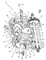
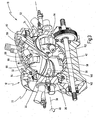
- Fig. 1 to 4 is a provided with the general reference numeral 10 shown oscillating piston engine. Further details of the oscillating piston engine 10 are in the Fig. 5 to 10 shown.
- the oscillating piston engine 10 is generally designed as an internal combustion engine, but can also be used with appropriate modifications as a pump or as a compressor.
- the oscillating piston engine 10 has a housing 12, which in Fig. 1 is shown closed.
- the housing 12 has a central housing portion 14 which is spherical.
- the middle housing portion 14 is composed of two housing halves 16 and 18, which are interconnected via a flange 20.
- the housing 12 further has a first end face 22 and a second end face 24, which lies opposite the first end face 22.
- the first end face 22 is formed by a front-side housing cover 26 and the second end face 24 by a front-side housing cover 28.
- the housing cover 26 and 28 are connected to the central housing portion 14 and the housing halves 16 and 18, respectively.
- the housing cover 26 and 28 are of the middle Housing portion 14 is removable, as well as the housing half 16 of the housing half 18 is removable.
- Fig. 2 to 4 inside the housing 12 four pistons 30 to 36 are arranged.
- the pistons 30 to 36 can rotate together in the housing 12 about an axis of rotation 38 according to an arrow 40.
- the axis of rotation 38 passes through the center of the spherical interior of the housing 12 and is fixed to the housing, ie, does not change its position relative to the housing 12 during the rotation of the pistons 32 to 36.
- the pistons 30 to 36 when circulating about the axis of rotation 38 perform a rotational movement superimposed on the rotational movement.
- the pistons 30 and 32 perform reciprocating pivotal movements about a first pivot axis 42 which perpendicularly intersects the axis of rotation 38 at the center of the interior of the housing 12, while the pistons 34 and 36 reciprocate pivotal movements about the axis of rotation 38 to execute a second pivot axis 44, which also perpendicularly intersects the axis of rotation 38 in the center of the interior of the housing 12, but is also perpendicular to the pivot axis 42.
- the pivot axes 42 and 44 also run with the pistons 30 to 36 about the axis of rotation 38.
- the instantaneous pivot plane of the pistons 30 and 32 is always perpendicular to the instantaneous pivot plane of the pistons 34 and 36th
- Both the axis of rotation 38 and the pivot axes 42 and 44 are to be understood here as geometric axes.
- Each of the pistons has an end surface, ie, the piston 30 has an end surface 46, the piston 32 has an end surface 48, the piston 34 has an end surface 50, and the piston 36 has an end surface 52, the latter being directed toward the latter Fig. 2 is covered by another component.
- the pistons 30 and 32 form a first pair of pistons whose end surfaces 46 and 48 face each other.
- the end surfaces 46 and 48 define a first working chamber 54.
- the pistons 34 and 36 form a second pair of pistons whose end surfaces 50 and 52 face each other and define a second working chamber 56. According to the reciprocating pivotal movements of the pistons 30 and 32 or 34 and 36, the volumes of the working chambers 54 and 56 increase and decrease, with the working chambers 54 and 56 always increasing or decreasing in the same direction.
- the pistons 30 to 36 are arranged in the housing 12 so that the axis of rotation 38 passes through both working chambers 54 and 56, preferably in each circulating and pivoting position of the pistons 30 to 36 centrally.
- each piston has a running member, namely the piston 30 is a running member 58 (FIGS. Fig. 3 and 4 ), the piston 32 is a running member 60 (see. Fig. 2 to 4 ), the piston 34 is a running member 62 (see. Fig. 2 ) and the piston 36, a running member 64 (see. Fig. 3 and 4 ).
- the running members 58 to 64 are here designed as rollers, wherein each running member 58-64 is rotatably mounted on the associated piston 30-36.
- the running members 58 and 60 of the pistons 30 and 32 is associated with a first control cam 66, which is formed on a control cam member 68.
- a second control cam 70 on the control cam member 68 is associated with the race members 62 and 64 of the pistons 34 and 36.
- the running members 58 and 60 thus run along the same cam 66, and the running members 62 and 64 along the same cam 70th
- the cams 66 and 70 are fully formed around the rotation axis 38 around and have a contour or KurvenScienceurig, which makes it possible to derive the pivotal movement of the pistons 30 and 32 and 34 and 36 from the orbital motion around the axis of rotation 38 around.
- the pistons 30 to 36 are slidably mounted in the housing 12 in a piston cage 72 which revolves around the axis of rotation 38 together with the pistons 30 to 36 and which in FIG Fig. 5 together with the pistons 30 to 36, but without the housing 12, is shown.
- the pistons are secured, for example by means not shown tongue and groove connections against rotation or tilting.
- the piston cage 72 has according to Fig. 4 a piston 74 and 36 associated bore 74 and according to Fig. 2 a bore 76 associated with pistons 30 and 32.
- the pistons 34 and 36 are slidably mounted, and the pistons 30 and 32 are slidably mounted in the bore 76.
- the bore 76 defines the working chamber 54
- the bore 74 defines together with the end surfaces 50 and 52 of the pistons 34 and 36 the working chamber 56. Due to the 90 ° entangled arrangement of the pistons 30 and 32 with respect to the pistons 34 and 36 and the holes 74 and 76 are perpendicular to each other in the piston cage 72 executed.
- the bores 74 and 76 are provided in a respective main bearing portion 78 (bore 74) and main bearing portion 80 (bore 76).
- the main bearing portions 78 and 80 of the piston cage 72 is rotatably mounted in the housing 12 via bearings 82 and 84 about the axis of rotation 38.
- the piston cage 72 serves not only for supporting the pistons 30 to 36, but also for tapping the rotational movement from or onto a drive / output shaft 86.
- the piston cage 72 is provided at its ends with an external toothing 88 or 90, of which at least one, in the illustrated embodiment, the external teeth 88 with a gear 92 which is connected to the output shaft 86, meshes.
- the output shaft 86 is therefore not arranged coaxially on the axis of rotation 38 in the rotary piston machine 10, but off-axis, whereby the gas exchange control of the oscillating piston engine 10 to be described below is made possible.
- the working chambers 54 and 56 in which a fuel-air mixture is compressed and ignited and expands after ignition, allow a gas exchange, i. air and fuel must be periodically introduced into the working chambers 54 and 56 and the combusted fuel-air mixture ejected from the working chambers 54 and 56 again.
- the gas exchange openings in the housing 12 are required, which are described below.
- the gas exchange openings are provided in the end faces 22 and 24 of the housing 12, i. near the axis of rotation 38, but eccentric to this, provided.
- the oscillating piston engine 10 has two working chambers 54 and 56, which are, however, formed symmetrically to each other, the gas exchange openings in the end faces 22 and 24 are equal to an offset of 180 ° about the axis of rotation 38 formed to each other, so that subsequently only the gas exchange openings on the end face 22 of the housing 12 are described.
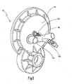
- Fig. 7 shows an interior view of the housing cover 26, which forms the end face 22 of the housing 12, and Fig. 6 shows an exterior view of the housing cover 26th
- a first gas exchange opening 94 and a second gas exchange opening 96 are formed in the frontal housing cover 26.
- the gas exchange port 94 is for introducing gas, in the present case for introducing combustion air into the working chamber 56, and the gas exchange port 96 is for discharging a gas from the working chamber 56, here for discharging combusted fuel-air mixture.
- the gas exchange opening 94 is associated with a nozzle 98, which is combined in the embodiment shown with an injection nozzle 100 for injecting a fuel together with the combustion air into the working chamber 56.
- an injection nozzle 100 for injecting a fuel together with the combustion air into the working chamber 56.
- direct injection may also be provided for the oscillating piston engine 10, i. the injection nozzle 100 is then separated from the nozzle 98.
- the gas exchange opening 96 is associated with a nozzle 102, which serves to connect the oscillating piston engine 10 to an exhaust system.
- the gas exchange openings 94 and 96 are arranged on the end-side housing cover 28 eccentrically with respect to the axis of rotation 38. How out Fig. 7 It can be seen that the gas exchange openings 94 and 96 are not formed as with the same opening cross section through the end-side housing cover 28 holes, but extend from the outside to the inside of the front-side housing cover 28.
- the gas exchange opening 94 has a cavernous or funnel-shaped recess 104, while the Gas exchange opening 96 a corresponding cavernous recess 106 has.
- the outline of the cavernous recesses 104 and 106 is formed approximately circular sector-shaped.
- the cavernous depressions or recesses 104 and 106 act as funnels for the respective gas inlet or gas outlet.
- the circulation angle is in Fig. 7 each about 70 °.
- the gas exchange openings 94 and 96 are separated by a web 108.
- the web 108 has seen in the direction of rotation about the axis of rotation 38 has a smaller angular extent than the two cavernous depressions or recesses 104 and 106, in the present case of about 40 °.
- the gas exchange openings 94 and 96 in the front-side housing cover 26 of the end face 22 represent the one part of the gas exchange control of the oscillating piston engine 10.
- the other part of the gas exchange control of the oscillating piston engine 10 is taken over by the piston cage 72.
- the piston cage 72 has a front side housing cover 26 of the end face 22 of the housing 12 directly opposite End face 110, which is convexly curved with the same radius of curvature on the outside in accordance with the inside concave configuration of the front-side housing cover 26.
- an opening 112 is present, which passes through the end face 110.
- the opening 112 has an opening cross-section which essentially has the shape of a circular sector.
- the width or maximum width of the opening 112 seen in the circumferential direction about the axis of rotation 38 is smaller than the minimum width or width of the web 108 in the front-side housing cover 26.
- the opening 112 is like the gas exchange openings 94 and 96 arranged eccentrically to the axis of rotation 38 ,
- the opening 112 When revolving the piston cage 72 about the axis of rotation 38, the opening 112 passes over its immediately opposite surface of the inside of the frontal housing cover 26, and depending on the circulation position, the opening 112 successively covers the gas exchange opening 96 and the gas exchange opening 94 and of course the remaining closed area 114 of the end face 110 opposite surface of the front-side housing cover 26 including the web 108th
- the end face 110 of the piston cage 72 is over the entire surface, i. closed,.
- a sealing arrangement 122 is provided, specifically in the embodiment shown on the end face 110 of the piston cage 72 itself.
- the seal assembly 122 includes a radially outer annular seal 124, a radially inner annular seal 126 and a plurality of radially extending or radially arranged seals 128 which are disposed between the radially inner annular seal 126 and the radially outer annular seal 124 and connect them together.
- the radially inner annular seal 126 seals against the central opening 116, and the radially outer annular seal 124 against the radially outer region of the end face 110 of the piston cage 72.
- seals 124 to 132 of the sealing arrangement 122 are integrally formed with each other and received in corresponding grooves in the outer side of the end face 110 of the piston cage 72.
- the seals 124 to 132 are resilient, in particular in the aforementioned grooves, for example, mounted on compression spring members, so that the seals 124 to 132 are pressed by spring force against the inside of the front-side housing cover 26.
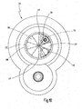
- Fig. 8 to 10 show various relative positions between the opening 112 in the end face 110 of the piston cage 72 and the gas exchange openings 94 and 96 in the front-side housing cover 26th
- the piston cage 72 is in a circulating position about the axis of rotation 38, in which the opening 112 communicates with the gas exchange opening 96. While the opening 112 sweeps over the gas exchange opening 96, a discharge of combusted fuel-air mixture from the working chamber 54 takes place. Meanwhile, the pistons 30 and 32 pivot out of the in Fig. 2 illustrated UT position on the in Fig. 4 illustrated intermediate position in the in Fig. 3 shown TDC position. For this pivoting stroke, the pistons 30 and 32 need a circulation path of 90 ° about the axis of rotation 38. During the ejection process, the gas exchange opening 94 is completely sealed against the working chamber 54, via the seal assembly 122nd
- the opening 112 slides in the end face 110 of the piston cage 72 according to Fig. 10 via the gas exchange opening 94, whereby fuel-air mixture is sucked through the gas exchange opening 94 in the working chamber 54.
- the process of the intake or suction of the fuel-air mixture is again about less than 90 ° of the rotational movement of the pistons 30 and 32 about the axis of rotation 38.
- the opening 112 is not aligned more with the gas exchange opening 94, and the working chamber 54 is now completely sealed against the gas exchange openings 94 and 96 again.
- the pistons 30 and 32 pivot toward each other again, whereby the previously admitted or sucked in fuel-air mixture is compressed until the piston 30 and 32 again reaches the TDC position to have.
- the opening 112 is located approximately at the height of a point 136 in Fig. 10 .
- the now maximally compressed fuel-air mixture is then ignited via the spark plug 120, and the ensuing expansion of the fuel-air mixture then takes place during the renewed transition of the pistons 30 and 32 from their TDC position to their BDC position via a further 90 ° circulation path about the axis of rotation 38.
- the end surfaces of the pistons 30 to 36 have a trough-like depression in their respective region which faces the end face of the piston cage 72, as shown for the pistons 30 and 32 by the reference numerals 140 and 142.
- the trough-like depressions 140 and 142 which are also provided corresponding to the piston 34 and 36, cause that in the TDC position of the piston 30 and 32 still a finite volume of the working chamber 54 remains, whereby upon ignition of the in the working chamber 54 just compressed fuel-air mixture, the pistons 30 and 32 are pushed apart with an optimal leverage.
- the chambers 30 and 32 of the working chamber 54 facing away from each rear chambers 150 and 152 are associated, which shrink in volume as the working chamber 54 increases, and vice versa.
- the chambers 150 and 152 may be used as pre-compression chambers for precompressing combustion air when the pistons 30 and 32 are moved apart, in which case in the UT position of the pistons 30 and 32 the precompressed combustion air is introduced into the piston 30 via a valve arrangement (not shown) and 32 can be injected therethrough into the working chamber 54.
- Comparable rearward chambers or admission pressure chambers can be provided correspondingly for the pistons 34 and 36.
- Fig. 1 is on the housing 12 further comprises an air inlet 154 and a corresponding air outlet 156, wherein the air inlet 154 is supplied with cooling air for the interior of the housing 12 and can be discharged via the air outlet 156 again. Furthermore, a water inlet 158 is provided, via which cooling water for the cooling of the housing 12 itself can be inserted, wherein the water is then removed via a water outlet 160 again.
- An oil inlet 162 for the lubrication and cooling of the rotating parts of the oscillating piston engine 10, in particular the piston cage 72 and the pistons 30 to 36 and an oil outlet 164 are also provided on the housing 12.
Landscapes
- Engineering & Computer Science (AREA)
- Mechanical Engineering (AREA)
- General Engineering & Computer Science (AREA)
- Chemical & Material Sciences (AREA)
- Combustion & Propulsion (AREA)
- Pistons, Piston Rings, And Cylinders (AREA)
- Compressors, Vaccum Pumps And Other Relevant Systems (AREA)
Claims (12)
- Moteur à pistons oscillants, comprenant un carter (12), dans lequel sont disposés un premier piston et au moins un deuxième piston (30, 32), lesquels peuvent tourner conjointement dans le carter (12) autour d'un axe de rotation (38) solidaire du carter et qui exécutent des mouvements oscillants alternatifs en sens contraire les uns par rapport aux autres autour d'un axe de pivotement (42) s'étendant de manière perpendiculaire par rapport à l'axe de rotation (38) en passant par le centre du carter, lorsqu'ils tournent autour de l'axe de rotation (38), sachant qu'une chambre de travail (54) est disposée entre des surfaces d'extrémité (46, 48) tournées les unes vers les autres du premier piston et d'au moins le deuxième piston (30, 32), et comprenant également au moins un orifice de changement de gaz (94, 96) dans le carter (12) servant à faire entrer un gaz dans la chambre de travail (54) ou à l'évacuer hors cette dernière et sachant que l'axe de rotation (38) s'étend à travers la chambre de travail (54), caractérisé en ce que le premier piston (30) et le deuxième piston (32) au moins au nombre de un sont logés de manière glissante dans une cage de piston (72), qui est disposée dans le carter (12) de manière concentrique par rapport à l'axe de rotation (38), de manière à pouvoir tourner autour de ce dernier et qui tourne conjointement avec les pistons (30, 32) autour de l'axe de rotation (38), en ce que l'orifice de changement de gaz (94, 96) au moins au nombre de un, par rapport à l'axe de rotation (38), est disposé au niveau d'un côté frontal (22) du carter (12) de manière excentrique, et en ce qu'un côté frontal (110) de surface pleine de la cage de piston (72) fait face au côté frontal (22) du carter (12), ledit côté frontal de surface pleine présentant un orifice (112) excentrique délimité dans la direction de rotation autour de l'axe de rotation (38), sachant que l'écoulement du gaz de travail à travers l'orifice de changement de gaz (94, 96) au moins au nombre de un est orienté essentiellement de manière axiale par rapport à l'axe de rotation.
- Moteur à pistons oscillants selon la revendication 1, caractérisé en ce que l'orifice de changement de gaz (94 96) au moins au nombre de un s'élargit dans la section transversale de l'orifice en partant du côté extérieur en direction du côté intérieur du côté frontal (22) du carter (12).
- Moteur à pistons oscillants selon la revendication 1 ou 2, caractérisé en ce qu'une faible largeur maximale de l'orifice de changement de gaz (94, 96) au moins au nombre de un s'étend, vu dans la direction de rotation autour de l'axe de rotation (38), sur un angle supérieur à 30° et inférieur à 90°.
- Moteur à pistons oscillants selon l'une quelconque des revendications 1 à 3, caractérisé en ce qu'un deuxième orifice de changement de gaz (94) est disposé de manière excentrique au niveau du côté frontal (22) du carter (12), sachant que l'orifice de changement de gaz (96) au moins au nombre de un sert à évacuer un gaz hors de la chambre de travail (54) et que le deuxième orifice de changement de gaz (94) sert à faire entrer un gaz dans la chambre de travail (54) et sachant que l'orifice (112) du côté frontal (110) de la cage de piston (72) communique avec l'orifice de changement de gaz au moins au nombre de un et le deuxième orifice de changement de gaz (96, 94) lors de la rotation autour de l'axe de rotation les uns après les autres, toutefois sans chevauchement dans le temps.
- Moteur à pistons oscillants selon la revendication 4, caractérisé en ce que l'orifice de changement de gaz (96) au moins au nombre de un servant à évacuer du gaz, vu dans la direction de rotation de la cage de piston (72), est disposé avant le deuxième orifice de changement de gaz (94) servant à faire entrer le gaz.
- Moteur à pistons oscillants selon la revendication 4 ou 5, caractérisé en ce que l'orifice de changement de gaz (96) au moins au nombre de un et le deuxième orifice de changement de gaz (94) sont séparés l'un de l'autre par une entretoise (108) vus dans la direction de rotation de la cage de piston (72), laquelle est au moins légèrement plus large que la largeur de l'orifice (112) de la cage de piston (72), sachant que l'entretoise (108), vue dans la direction de rotation, s'étend sur un angle compris entre environ 20° et environ 60°.
- Moteur à pistons oscillants selon la revendication 6, caractérisé en ce que l'entretoise (108) s'étend sur un angle compris entre environ 30° et environ 50°.
- Moteur à pistons oscillants selon l'une quelconque des revendications 1 à 7, caractérisé en ce qu'est présent entre le côté frontal (22) du carter (12) et le côté frontal (110) de la cage de piston (72) un ensemble de joints d'étanchéité (122), qui présente au moins un joint d'étanchéité, qui étanchéifie l'orifice de changement de gaz (94, 96) au moins au nombre de un par rapport au côté frontal (110) de la cage de piston (72).
- Moteur à pistons oscillants selon la revendication 8, caractérisé en ce que l'ensemble de joints d'étanchéité (122) est prévu au niveau de la cage de piston (72) et présente un joint d'étanchéité annulaire (124) extérieur radialement par rapport à l'axe de rotation (38), éventuellement un joint d'étanchéité annulaire (126) intérieur radialement et au moins deux joints d'étanchéité (130, 132) espacés l'un de l'autre dans la direction périphérique et s'étendant radialement au moins de manière approchante, lesquels sont reliés aux joints d'étanchéité annulaires (124, 126) et sont disposés de part et d'autre de l'orifice (112) de la cage de piston (72).
- Moteur à pistons oscillants selon la revendication 9, caractérisé en ce que l'ensemble de joints d'étanchéité (122) présente plus de deux joints d'étanchéité (128, 130, 132) s'étendant au moins de manière approchante radialement, lesquels sont répartis de manière homogène de préférence dans la direction de rotation autour de l'axe de rotation (38).
- Moteur à pistons oscillants selon l'une quelconque des revendications 1 à 10, caractérisé en ce qu'un autre orifice central (118) est présent dans le côté frontal (22) du carter (12) et qu'également un autre orifice central (116) est présent dans le côté frontal (110) de la cage de piston (72).
- Moteur à pistons oscillants selon l'une quelconque des revendications 1 à 11, caractérisé en ce que les surfaces d'extrémité (46, 48) des pistons (30, 32) présentent un creux (140, 142) dans une zone, qui est tournée vers le côté frontal (110) de la cage de piston (72).
Applications Claiming Priority (2)
| Application Number | Priority Date | Filing Date | Title |
|---|---|---|---|
| DE102006009198A DE102006009198B4 (de) | 2006-02-22 | 2006-02-22 | Schwenkkolbenmaschine |
| PCT/EP2007/001488 WO2007096140A1 (fr) | 2006-02-22 | 2007-02-21 | Moteur à pistons oscillants |
Publications (2)
| Publication Number | Publication Date |
|---|---|
| EP1987232A1 EP1987232A1 (fr) | 2008-11-05 |
| EP1987232B1 true EP1987232B1 (fr) | 2013-05-15 |
Family
ID=38110123
Family Applications (1)
| Application Number | Title | Priority Date | Filing Date |
|---|---|---|---|
| EP07711614.3A Active EP1987232B1 (fr) | 2006-02-22 | 2007-02-21 | Moteur à pistons oscillants |
Country Status (6)
| Country | Link |
|---|---|
| US (1) | US7866284B2 (fr) |
| EP (1) | EP1987232B1 (fr) |
| JP (1) | JP4638945B2 (fr) |
| CN (1) | CN100504033C (fr) |
| DE (1) | DE102006009198B4 (fr) |
| WO (1) | WO2007096140A1 (fr) |
Families Citing this family (8)
| Publication number | Priority date | Publication date | Assignee | Title |
|---|---|---|---|---|
| DE502005004001D1 (de) * | 2004-04-06 | 2008-06-19 | Peraves Ag | Schwenkkolbenmaschine und fahrzeug mit einer solchen schwenkkolbenmaschine |
| JP4818280B2 (ja) * | 2005-02-25 | 2011-11-16 | ヘルベルト ヒュットリン | 振動ピストン式機械 |
| DE102005062529B4 (de) * | 2005-12-16 | 2007-09-20 | Hüttlin, Herbert, Dr. h.c. | Schwenkkolbenmaschine |
| DE102006009197B4 (de) * | 2006-02-22 | 2008-09-11 | Hüttlin, Herbert, Dr. h.c. | Schwenkkolbenmaschine |
| DE102010022012A1 (de) | 2010-05-25 | 2011-12-01 | Herbert Hüttlin | Aggregat, insbesondere Hybridmotor, Stromgenerator oder Kompressor |
| DE102011001551B4 (de) * | 2011-03-25 | 2017-11-02 | Philipp Diem | Verbrennungsmotor mit einem um seine Achse drehbaren Rotor |
| BR122020026845B1 (pt) | 2011-11-02 | 2021-04-13 | Ceres, Inc | Método de aumento do rendimento de planta em solo contendo níveis elevados de al3+, método de aumento da tolerância de uma planta |
| CN104948453B (zh) * | 2014-03-26 | 2019-08-13 | 天津市石化通用机械研究所 | 曲柄连杆机构驱动的托盘活塞摇摆压送流体机 |
Family Cites Families (20)
| Publication number | Priority date | Publication date | Assignee | Title |
|---|---|---|---|---|
| US2197959A (en) * | 1937-06-02 | 1940-04-23 | Roland Stanley Quartermaine | Rotary prime mover, pump, compressor, and the like |
| US3075506A (en) * | 1961-07-31 | 1963-01-29 | Differential Hydraulics Inc | Spherical trajectory rotary power device |
| US3169487A (en) * | 1961-11-29 | 1965-02-16 | Yehan Numata | High pressure vane pump |
| US3934559A (en) * | 1975-03-10 | 1976-01-27 | Sphero International Company | Anti-pollutant spherical rotary engine with automatic supercharger |
| JPS5237677A (en) * | 1975-09-18 | 1977-03-23 | Yasuo Ueno | Spherical rotary piston mechanism |
| US4132213A (en) * | 1977-03-29 | 1979-01-02 | Weaver R Homer | Rotary engine |
| JPS608401A (ja) * | 1983-06-20 | 1985-01-17 | ロジヤ−・バジユラツ | 揺動室およびピストン付き機械 |
| NO160540C (no) * | 1986-11-24 | 1989-04-26 | 3 D Int As | Kraftomsetningsmaskin med stempler som beveges i en dreiebevegelse i et sfaerisk hus. |
| CN1075531A (zh) * | 1992-02-20 | 1993-08-25 | 张全 | 球形变容机 |
| NZ270736A (en) * | 1995-03-17 | 1998-12-23 | Noel Stephen Duke | Wobble plate engine with pairs of rotating cylinders around output shaft, with port plates in end covers |
| IL119105A0 (en) * | 1996-08-21 | 1996-11-14 | Volftsun Leonid | Rotary vane machine |
| JP2003507630A (ja) * | 1999-08-25 | 2003-02-25 | グレン・アレキサンダー・トンプソン | 可変容積装置およびそのシステム |
| US6325038B1 (en) * | 2000-01-18 | 2001-12-04 | Spherical Propulsion, Llc | Spherical internal combustion engine |
| DK1472435T3 (da) * | 2002-02-06 | 2007-02-12 | Herbert Huettlin | Svingstempelmaskine |
| DE10361566B4 (de) * | 2003-12-23 | 2006-09-07 | Hüttlin, Herbert, Dr. h.c. | Schwenkkolbenmaschine |
| DE502005004001D1 (de) * | 2004-04-06 | 2008-06-19 | Peraves Ag | Schwenkkolbenmaschine und fahrzeug mit einer solchen schwenkkolbenmaschine |
| JP4818280B2 (ja) | 2005-02-25 | 2011-11-16 | ヘルベルト ヒュットリン | 振動ピストン式機械 |
| DE102005010775B3 (de) * | 2005-02-25 | 2006-04-20 | Hüttlin, Herbert, Dr. h.c. | Schwenkkolbenmaschine |
| DE102005024751B4 (de) * | 2005-02-25 | 2015-10-22 | Herbert Hüttlin | Schwenkkolbenmaschine |
| DE102005026661A1 (de) * | 2005-05-31 | 2006-12-07 | Hüttlin, Herbert, Dr. h.c. | Rotationskolbenmaschine |
-
2006
- 2006-02-22 DE DE102006009198A patent/DE102006009198B4/de not_active Expired - Fee Related
- 2006-06-02 CN CNB2006100886751A patent/CN100504033C/zh not_active Expired - Fee Related
-
2007
- 2007-02-21 EP EP07711614.3A patent/EP1987232B1/fr active Active
- 2007-02-21 JP JP2008555688A patent/JP4638945B2/ja not_active Expired - Fee Related
- 2007-02-21 WO PCT/EP2007/001488 patent/WO2007096140A1/fr not_active Ceased
-
2008
- 2008-08-22 US US12/196,423 patent/US7866284B2/en not_active Expired - Fee Related
Also Published As
| Publication number | Publication date |
|---|---|
| JP4638945B2 (ja) | 2011-02-23 |
| EP1987232A1 (fr) | 2008-11-05 |
| CN100504033C (zh) | 2009-06-24 |
| JP2009527684A (ja) | 2009-07-30 |
| US20090038581A1 (en) | 2009-02-12 |
| DE102006009198B4 (de) | 2010-03-25 |
| US7866284B2 (en) | 2011-01-11 |
| CN101025089A (zh) | 2007-08-29 |
| WO2007096140A1 (fr) | 2007-08-30 |
| DE102006009198A1 (de) | 2007-08-23 |
Similar Documents
| Publication | Publication Date | Title |
|---|---|---|
| EP1987232A1 (fr) | Moteur à pistons oscillants | |
| DE3937359A1 (de) | Brennkraftmaschine | |
| EP1472435A1 (fr) | Moteur a pistons oscillants | |
| EP1339952B1 (fr) | Moteur a combustion interne a piston rotatif | |
| DE102005010775B3 (de) | Schwenkkolbenmaschine | |
| EP1355053B1 (fr) | Moteur rotatif à pistons | |
| EP1987233B1 (fr) | Machine à pistons oscillants | |
| EP0548297B1 (fr) | Moteur a pistons oscillants | |
| EP1856375B1 (fr) | Moteur à pistons oscillants | |
| DE2449008A1 (de) | Drehkolbenverbrennungskraftmaschine | |
| DE102005038447B3 (de) | Schwenkkolbenmaschine | |
| EP1885998A1 (fr) | Machine a pistons rotatifs | |
| DE2931943A1 (de) | Aussenachsige drehkolbenmaschine | |
| DE102005024751B4 (de) | Schwenkkolbenmaschine | |
| EP2205832B1 (fr) | Machine à pistons | |
| DE2416155A1 (de) | Verfahren zum betreiben eines verbrennungsmotors sowie nach dem verfahren arbeitender motor | |
| DE102009018839B3 (de) | Arbeitskraftmaschine | |
| EP2179140A1 (fr) | Machine à piston rotatif | |
| DE2611642A1 (de) | Drehkolben-brennkraftmaschine | |
| WO2006084649A1 (fr) | Machine a pistons pivotants et systeme de machine a pistons pivotants | |
| AT404159B (de) | Rotationskolbenmaschine | |
| EP2612985B1 (fr) | Moteur à combustion interne à pistons rotatifs | |
| DE2835826A1 (de) | Rotationskolbenverdichter mit zusammenwirkenden laeufern | |
| WO2007026323A1 (fr) | Moteur a piston rotatif | |
| DE19522846A1 (de) | Rotationskolbenmaschine |
Legal Events
| Date | Code | Title | Description |
|---|---|---|---|
| PUAI | Public reference made under article 153(3) epc to a published international application that has entered the european phase |
Free format text: ORIGINAL CODE: 0009012 |
|
| 17P | Request for examination filed |
Effective date: 20080813 |
|
| AK | Designated contracting states |
Kind code of ref document: A1 Designated state(s): AT BE BG CH CY CZ DE DK EE ES FI FR GB GR HU IE IS IT LI LT LU LV MC NL PL PT RO SE SI SK TR |
|
| AX | Request for extension of the european patent |
Extension state: HR RS |
|
| 17Q | First examination report despatched |
Effective date: 20110518 |
|
| RAX | Requested extension states of the european patent have changed |
Extension state: RS Payment date: 20080813 Extension state: HR Payment date: 20080813 |
|
| GRAP | Despatch of communication of intention to grant a patent |
Free format text: ORIGINAL CODE: EPIDOSNIGR1 |
|
| GRAS | Grant fee paid |
Free format text: ORIGINAL CODE: EPIDOSNIGR3 |
|
| GRAA | (expected) grant |
Free format text: ORIGINAL CODE: 0009210 |
|
| AK | Designated contracting states |
Kind code of ref document: B1 Designated state(s): AT BE BG CH CY CZ DE DK EE ES FI FR GB GR HU IE IS IT LI LT LU LV MC NL PL PT RO SE SI SK TR |
|
| AX | Request for extension of the european patent |
Extension state: HR RS |
|
| REG | Reference to a national code |
Ref country code: GB Ref legal event code: FG4D Free format text: NOT ENGLISH Ref country code: CH Ref legal event code: EP |
|
| REG | Reference to a national code |
Ref country code: AT Ref legal event code: REF Ref document number: 612262 Country of ref document: AT Kind code of ref document: T Effective date: 20130615 |
|
| REG | Reference to a national code |
Ref country code: IE Ref legal event code: FG4D Free format text: LANGUAGE OF EP DOCUMENT: GERMAN |
|
| REG | Reference to a national code |
Ref country code: DE Ref legal event code: R096 Ref document number: 502007011760 Country of ref document: DE Effective date: 20130711 |
|
| REG | Reference to a national code |
Ref country code: LT Ref legal event code: MG4D |
|
| REG | Reference to a national code |
Ref country code: NL Ref legal event code: VDEP Effective date: 20130515 |
|
| PG25 | Lapsed in a contracting state [announced via postgrant information from national office to epo] |
Ref country code: SI Free format text: LAPSE BECAUSE OF FAILURE TO SUBMIT A TRANSLATION OF THE DESCRIPTION OR TO PAY THE FEE WITHIN THE PRESCRIBED TIME-LIMIT Effective date: 20130515 Ref country code: FI Free format text: LAPSE BECAUSE OF FAILURE TO SUBMIT A TRANSLATION OF THE DESCRIPTION OR TO PAY THE FEE WITHIN THE PRESCRIBED TIME-LIMIT Effective date: 20130515 Ref country code: ES Free format text: LAPSE BECAUSE OF FAILURE TO SUBMIT A TRANSLATION OF THE DESCRIPTION OR TO PAY THE FEE WITHIN THE PRESCRIBED TIME-LIMIT Effective date: 20130826 Ref country code: SE Free format text: LAPSE BECAUSE OF FAILURE TO SUBMIT A TRANSLATION OF THE DESCRIPTION OR TO PAY THE FEE WITHIN THE PRESCRIBED TIME-LIMIT Effective date: 20130515 Ref country code: PT Free format text: LAPSE BECAUSE OF FAILURE TO SUBMIT A TRANSLATION OF THE DESCRIPTION OR TO PAY THE FEE WITHIN THE PRESCRIBED TIME-LIMIT Effective date: 20130916 Ref country code: IS Free format text: LAPSE BECAUSE OF FAILURE TO SUBMIT A TRANSLATION OF THE DESCRIPTION OR TO PAY THE FEE WITHIN THE PRESCRIBED TIME-LIMIT Effective date: 20130915 Ref country code: LT Free format text: LAPSE BECAUSE OF FAILURE TO SUBMIT A TRANSLATION OF THE DESCRIPTION OR TO PAY THE FEE WITHIN THE PRESCRIBED TIME-LIMIT Effective date: 20130515 Ref country code: GR Free format text: LAPSE BECAUSE OF FAILURE TO SUBMIT A TRANSLATION OF THE DESCRIPTION OR TO PAY THE FEE WITHIN THE PRESCRIBED TIME-LIMIT Effective date: 20130816 |
|
| PG25 | Lapsed in a contracting state [announced via postgrant information from national office to epo] |
Ref country code: PL Free format text: LAPSE BECAUSE OF FAILURE TO SUBMIT A TRANSLATION OF THE DESCRIPTION OR TO PAY THE FEE WITHIN THE PRESCRIBED TIME-LIMIT Effective date: 20130515 Ref country code: BG Free format text: LAPSE BECAUSE OF FAILURE TO SUBMIT A TRANSLATION OF THE DESCRIPTION OR TO PAY THE FEE WITHIN THE PRESCRIBED TIME-LIMIT Effective date: 20130815 |
|
| PG25 | Lapsed in a contracting state [announced via postgrant information from national office to epo] |
Ref country code: LV Free format text: LAPSE BECAUSE OF FAILURE TO SUBMIT A TRANSLATION OF THE DESCRIPTION OR TO PAY THE FEE WITHIN THE PRESCRIBED TIME-LIMIT Effective date: 20130515 |
|
| PG25 | Lapsed in a contracting state [announced via postgrant information from national office to epo] |
Ref country code: EE Free format text: LAPSE BECAUSE OF FAILURE TO SUBMIT A TRANSLATION OF THE DESCRIPTION OR TO PAY THE FEE WITHIN THE PRESCRIBED TIME-LIMIT Effective date: 20130515 Ref country code: CZ Free format text: LAPSE BECAUSE OF FAILURE TO SUBMIT A TRANSLATION OF THE DESCRIPTION OR TO PAY THE FEE WITHIN THE PRESCRIBED TIME-LIMIT Effective date: 20130515 Ref country code: SK Free format text: LAPSE BECAUSE OF FAILURE TO SUBMIT A TRANSLATION OF THE DESCRIPTION OR TO PAY THE FEE WITHIN THE PRESCRIBED TIME-LIMIT Effective date: 20130515 Ref country code: DK Free format text: LAPSE BECAUSE OF FAILURE TO SUBMIT A TRANSLATION OF THE DESCRIPTION OR TO PAY THE FEE WITHIN THE PRESCRIBED TIME-LIMIT Effective date: 20130515 |
|
| PG25 | Lapsed in a contracting state [announced via postgrant information from national office to epo] |
Ref country code: NL Free format text: LAPSE BECAUSE OF FAILURE TO SUBMIT A TRANSLATION OF THE DESCRIPTION OR TO PAY THE FEE WITHIN THE PRESCRIBED TIME-LIMIT Effective date: 20130515 Ref country code: IT Free format text: LAPSE BECAUSE OF FAILURE TO SUBMIT A TRANSLATION OF THE DESCRIPTION OR TO PAY THE FEE WITHIN THE PRESCRIBED TIME-LIMIT Effective date: 20130515 Ref country code: RO Free format text: LAPSE BECAUSE OF FAILURE TO SUBMIT A TRANSLATION OF THE DESCRIPTION OR TO PAY THE FEE WITHIN THE PRESCRIBED TIME-LIMIT Effective date: 20130515 |
|
| PLBE | No opposition filed within time limit |
Free format text: ORIGINAL CODE: 0009261 |
|
| STAA | Information on the status of an ep patent application or granted ep patent |
Free format text: STATUS: NO OPPOSITION FILED WITHIN TIME LIMIT |
|
| 26N | No opposition filed |
Effective date: 20140218 |
|
| PGFP | Annual fee paid to national office [announced via postgrant information from national office to epo] |
Ref country code: CH Payment date: 20140319 Year of fee payment: 8 |
|
| REG | Reference to a national code |
Ref country code: DE Ref legal event code: R097 Ref document number: 502007011760 Country of ref document: DE Effective date: 20140218 |
|
| PGFP | Annual fee paid to national office [announced via postgrant information from national office to epo] |
Ref country code: FR Payment date: 20140319 Year of fee payment: 8 |
|
| PGFP | Annual fee paid to national office [announced via postgrant information from national office to epo] |
Ref country code: GB Payment date: 20140319 Year of fee payment: 8 |
|
| BERE | Be: lapsed |
Owner name: HUTTLIN, HERBERT Effective date: 20140228 |
|
| PG25 | Lapsed in a contracting state [announced via postgrant information from national office to epo] |
Ref country code: MC Free format text: LAPSE BECAUSE OF FAILURE TO SUBMIT A TRANSLATION OF THE DESCRIPTION OR TO PAY THE FEE WITHIN THE PRESCRIBED TIME-LIMIT Effective date: 20130515 Ref country code: LU Free format text: LAPSE BECAUSE OF FAILURE TO SUBMIT A TRANSLATION OF THE DESCRIPTION OR TO PAY THE FEE WITHIN THE PRESCRIBED TIME-LIMIT Effective date: 20140221 |
|
| REG | Reference to a national code |
Ref country code: IE Ref legal event code: MM4A |
|
| PG25 | Lapsed in a contracting state [announced via postgrant information from national office to epo] |
Ref country code: BE Free format text: LAPSE BECAUSE OF NON-PAYMENT OF DUE FEES Effective date: 20140228 Ref country code: IE Free format text: LAPSE BECAUSE OF NON-PAYMENT OF DUE FEES Effective date: 20140221 |
|
| REG | Reference to a national code |
Ref country code: AT Ref legal event code: MM01 Ref document number: 612262 Country of ref document: AT Kind code of ref document: T Effective date: 20140221 |
|
| PG25 | Lapsed in a contracting state [announced via postgrant information from national office to epo] |
Ref country code: AT Free format text: LAPSE BECAUSE OF NON-PAYMENT OF DUE FEES Effective date: 20140221 |
|
| REG | Reference to a national code |
Ref country code: CH Ref legal event code: PL |
|
| GBPC | Gb: european patent ceased through non-payment of renewal fee |
Effective date: 20150221 |
|
| PG25 | Lapsed in a contracting state [announced via postgrant information from national office to epo] |
Ref country code: LI Free format text: LAPSE BECAUSE OF NON-PAYMENT OF DUE FEES Effective date: 20150228 Ref country code: CH Free format text: LAPSE BECAUSE OF NON-PAYMENT OF DUE FEES Effective date: 20150228 |
|
| REG | Reference to a national code |
Ref country code: FR Ref legal event code: ST Effective date: 20151030 |
|
| PG25 | Lapsed in a contracting state [announced via postgrant information from national office to epo] |
Ref country code: GB Free format text: LAPSE BECAUSE OF NON-PAYMENT OF DUE FEES Effective date: 20150221 |
|
| PG25 | Lapsed in a contracting state [announced via postgrant information from national office to epo] |
Ref country code: FR Free format text: LAPSE BECAUSE OF NON-PAYMENT OF DUE FEES Effective date: 20150302 |
|
| PG25 | Lapsed in a contracting state [announced via postgrant information from national office to epo] |
Ref country code: CY Free format text: LAPSE BECAUSE OF FAILURE TO SUBMIT A TRANSLATION OF THE DESCRIPTION OR TO PAY THE FEE WITHIN THE PRESCRIBED TIME-LIMIT Effective date: 20130515 |
|
| PG25 | Lapsed in a contracting state [announced via postgrant information from national office to epo] |
Ref country code: TR Free format text: LAPSE BECAUSE OF FAILURE TO SUBMIT A TRANSLATION OF THE DESCRIPTION OR TO PAY THE FEE WITHIN THE PRESCRIBED TIME-LIMIT Effective date: 20130515 Ref country code: HU Free format text: LAPSE BECAUSE OF FAILURE TO SUBMIT A TRANSLATION OF THE DESCRIPTION OR TO PAY THE FEE WITHIN THE PRESCRIBED TIME-LIMIT; INVALID AB INITIO Effective date: 20070221 |
|
| PGFP | Annual fee paid to national office [announced via postgrant information from national office to epo] |
Ref country code: DE Payment date: 20180425 Year of fee payment: 12 |
|
| REG | Reference to a national code |
Ref country code: DE Ref legal event code: R119 Ref document number: 502007011760 Country of ref document: DE |
|
| PG25 | Lapsed in a contracting state [announced via postgrant information from national office to epo] |
Ref country code: DE Free format text: LAPSE BECAUSE OF NON-PAYMENT OF DUE FEES Effective date: 20190903 |