EP1987258B1 - Structure de support destinée à des meubles, en particulier des meubles de cuisine ou analogues - Google Patents
Structure de support destinée à des meubles, en particulier des meubles de cuisine ou analogues Download PDFInfo
- Publication number
- EP1987258B1 EP1987258B1 EP06779780A EP06779780A EP1987258B1 EP 1987258 B1 EP1987258 B1 EP 1987258B1 EP 06779780 A EP06779780 A EP 06779780A EP 06779780 A EP06779780 A EP 06779780A EP 1987258 B1 EP1987258 B1 EP 1987258B1
- Authority
- EP
- European Patent Office
- Prior art keywords
- uprights
- structure according
- crosspiece
- fact
- modular elements
- Prior art date
- Legal status (The legal status is an assumption and is not a legal conclusion. Google has not performed a legal analysis and makes no representation as to the accuracy of the status listed.)
- Not-in-force
Links
- 239000000463 material Substances 0.000 claims description 8
- 239000005871 repellent Substances 0.000 claims description 5
- 239000002184 metal Substances 0.000 claims description 4
- 238000005259 measurement Methods 0.000 claims description 3
- 230000000284 resting effect Effects 0.000 claims description 2
- 238000004140 cleaning Methods 0.000 description 4
- 230000008595 infiltration Effects 0.000 description 4
- 238000001764 infiltration Methods 0.000 description 4
- XLYOFNOQVPJJNP-UHFFFAOYSA-N water Substances O XLYOFNOQVPJJNP-UHFFFAOYSA-N 0.000 description 4
- WSFSSNUMVMOOMR-UHFFFAOYSA-N Formaldehyde Chemical compound O=C WSFSSNUMVMOOMR-UHFFFAOYSA-N 0.000 description 3
- 239000000853 adhesive Substances 0.000 description 3
- 230000001070 adhesive effect Effects 0.000 description 3
- 238000004519 manufacturing process Methods 0.000 description 3
- 238000004806 packaging method and process Methods 0.000 description 3
- 238000003860 storage Methods 0.000 description 3
- 239000000428 dust Substances 0.000 description 2
- 230000000694 effects Effects 0.000 description 2
- 229920005989 resin Polymers 0.000 description 2
- 239000011347 resin Substances 0.000 description 2
- 239000000126 substance Substances 0.000 description 2
- 230000008961 swelling Effects 0.000 description 2
- 230000015572 biosynthetic process Effects 0.000 description 1
- 230000003670 easy-to-clean Effects 0.000 description 1
- 239000003344 environmental pollutant Substances 0.000 description 1
- 230000002045 lasting effect Effects 0.000 description 1
- WSFSSNUMVMOOMR-NJFSPNSNSA-N methanone Chemical compound O=[14CH2] WSFSSNUMVMOOMR-NJFSPNSNSA-N 0.000 description 1
- 238000012986 modification Methods 0.000 description 1
- 230000004048 modification Effects 0.000 description 1
- 231100000719 pollutant Toxicity 0.000 description 1
- 238000002360 preparation method Methods 0.000 description 1
- 230000002035 prolonged effect Effects 0.000 description 1
- 230000002940 repellent Effects 0.000 description 1
- 238000004513 sizing Methods 0.000 description 1
- 230000009747 swallowing Effects 0.000 description 1
- 238000005406 washing Methods 0.000 description 1
Images


Classifications
-
- F—MECHANICAL ENGINEERING; LIGHTING; HEATING; WEAPONS; BLASTING
- F16—ENGINEERING ELEMENTS AND UNITS; GENERAL MEASURES FOR PRODUCING AND MAINTAINING EFFECTIVE FUNCTIONING OF MACHINES OR INSTALLATIONS; THERMAL INSULATION IN GENERAL
- F16B—DEVICES FOR FASTENING OR SECURING CONSTRUCTIONAL ELEMENTS OR MACHINE PARTS TOGETHER, e.g. NAILS, BOLTS, CIRCLIPS, CLAMPS, CLIPS OR WEDGES; JOINTS OR JOINTING
- F16B12/00—Jointing of furniture or the like, e.g. hidden from exterior
- F16B12/10—Jointing of furniture or the like, e.g. hidden from exterior using pegs, bolts, tenons, clamps, clips, or the like
- F16B12/12—Jointing of furniture or the like, e.g. hidden from exterior using pegs, bolts, tenons, clamps, clips, or the like for non-metal furniture parts, e.g. made of wood, of plastics
- F16B12/14—Jointing of furniture or the like, e.g. hidden from exterior using pegs, bolts, tenons, clamps, clips, or the like for non-metal furniture parts, e.g. made of wood, of plastics using threaded bolts or screws
-
- A—HUMAN NECESSITIES
- A47—FURNITURE; DOMESTIC ARTICLES OR APPLIANCES; COFFEE MILLS; SPICE MILLS; SUCTION CLEANERS IN GENERAL
- A47B—TABLES; DESKS; OFFICE FURNITURE; CABINETS; DRAWERS; GENERAL DETAILS OF FURNITURE
- A47B47/00—Cabinets, racks or shelf units, characterised by features related to dismountability or building-up from elements
- A47B47/04—Cabinets, racks or shelf units, characterised by features related to dismountability or building-up from elements made mainly of wood or plastics
-
- A—HUMAN NECESSITIES
- A47—FURNITURE; DOMESTIC ARTICLES OR APPLIANCES; COFFEE MILLS; SPICE MILLS; SUCTION CLEANERS IN GENERAL
- A47B—TABLES; DESKS; OFFICE FURNITURE; CABINETS; DRAWERS; GENERAL DETAILS OF FURNITURE
- A47B77/00—Kitchen cabinets
- A47B77/02—General layout, e.g. relative arrangement of compartments, working surface or surfaces, supports for apparatus
-
- A—HUMAN NECESSITIES
- A47—FURNITURE; DOMESTIC ARTICLES OR APPLIANCES; COFFEE MILLS; SPICE MILLS; SUCTION CLEANERS IN GENERAL
- A47B—TABLES; DESKS; OFFICE FURNITURE; CABINETS; DRAWERS; GENERAL DETAILS OF FURNITURE
- A47B2230/00—Furniture jointing; Furniture with such jointing
- A47B2230/07—Releasable locking means or connectors for fastening together parts of furniture
Definitions
- the present invention refers to a carrying structure for furniture, especially for kitchen furniture or the like.
- modular kitchens consisting of distinct modules such as, for instance, door units, units with drawers or baskets, wall units, units for supporting household appliances, sinks, cooktops, etc.
- modules normally consist of panels fastened together by means of adhesives or the like to define a compartment able to accommodate kitchen equipment such as household appliances (oven, dishwasher), or support shelves, baskets, drawers, etc.
- kitchen equipment such as household appliances (oven, dishwasher), or support shelves, baskets, drawers, etc.
- the known modules can be fitted together and arranged so as to define predetermined types of configurations, depending on the conformation of the interior to be furnished and specific aesthetic choices (either made during manufacture or by the end user).
- modules of pre-defined dimensions reduces the use of the inner compartment of the furniture units and restricts the relevant storage capacity.
- a further drawback of known kitchens is the difficulty in carrying out accurate cleaning operations, due in particular to the presence of spaces between the assembled modules, inside which dust and dirt in general gather.
- cleaning operations which are especially important for maintaining a suitable standard of hygiene inside an environment where food is prepared and cooked, the modules do in fact have to be separated and this operation is hard to do in the case of already-assembled kitchens.
- woody composition of the panels generally used to make the modules requires the limited use of water during cleaning operations so as to avoid infiltrations between one panel and another or inside the panels themselves, with the consequent possibility of swelling and/or the generation of mildew.
- woody panels normally used even when they are defined as “water repellent", are in any case partially subject to infiltration, especially at the joints between the surfaces and side edges of two panels.
- Another drawback consists in the difficulty during packaging, transport and assembly, due to the far-from-negligible overall dimensions of the single modules.
- each module consists, in general, of numerous panels (for example with a woody base) fastened together using potentially polluting adhesives that are harmful to people's health.
- resins are commonly used deriving from substances like formaldehyde, currently considered one of the most common pollutants of interiors. Molecules of formaldehyde are in fact released over time inside the environment and, though it is commonly thought that its concentration inside buildings is normally sufficiently reduced, prolonged exposure to large quantities or accidental swallowing can seriously affect people's health.
- Known kitchens are generally made of materials that are not fireproof, with increased risk of accidental fires, also in view of the presence of household appliances such as cooktops, ovens or the like.
- Document DE 14 29 602 A1 discloses an enclosure or cabinet particularly suitable for housing electrical apparatus, connection units or the like.
- Document EP 1 159 891 A discloses a modular framework for a shelf system made up of connectors in the shape of a cube with threaded bores in each face and connecting bars with threaded rods at their ends which fit into the bores. Removably carrying handles can be fitted into connectors at each end.
- these known solutions can be improved.
- the main aim of this invention is to eliminate the problems complained of above and associated with the known state of the art and to excogitate a carrying structure for furniture, especially for kitchen furniture or the like, which is versatile and adaptable to any type of environment or any type of aesthetic requirement.
- another purpose of the invention is to permit the sizing of the interior compartment in relation to specific storage requirements.
- Another purpose of the invention is to make cleaning easier so as to maintain an adequate standard of hygiene inside the environment.
- Another objective of the invention is to make a water-repellent structure which is not therefore liable to the damage notoriously caused by infiltrations and the presence of steam.
- Another purpose of the invention is to make kitchen packaging and transport operations easier.
- Another purpose of the invention is to avoid the use of polluting substances normally used to make kitchen furniture.
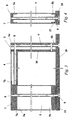
- a carrying structure for furniture especially to be employed in the kitchen furnishing industry, has been generally designated by reference numeral 1.
- Structure 1 comprises a plurality of modular elements 2, each of which featuring a pair of uprights 3 and a crosspiece 4.
- the crosspiece 4 has its ends associated with the uprights 3 by means of the interposition of temporary fastening means.
- each of the modular elements 2 comprises a front upright 5 and a rear upright 6, where the words "front” and “rear” refer, in this description and in a non-exclusive way, to the normal layout of the structure 1 after this has been positioned to furnish an interior.
- the temporary fastening means comprise a first joint 7, featuring a pair of lower protruding elements 7a and a pair of rear protruding elements 7b.
- the particular tubular configuration, open at the ends, of the uprights 3 and the crosspiece 4 permits the slotting in of the lower protruding elements 7a inside the opening defined at the upper end 5a of the front upright 5, and of the rear protruding elements 7b inside the opening defined at the front end 4a of the crosspiece 4 respectively.
- the fastening of the upper end 5a and front end 4a to the first joint 7 is done by means of threaded means 8 of the type commonly used, screws or the like, applied to an upper through hole 7c and a rear through hole 7d on first joint 7 respectively.
- the rear end 4b of the crosspiece 4 is fastened to the upper end 6a of the rear upright 6 by means of respective threaded means 8.
- first joint 7, uprights 3 and the relevant crosspiece 4 are however not to be ruled out.
- the modular elements can be associated with one another to make a hanging structure P or, alternatively, a ground structure T, both commonly used to furnish kitchens or the like.
- the modular elements 2 are associated with one another in a removable way by interposing cross connection elements 9, to delimit, below crosspieces 4, a compartment V for housing kitchen equipments or the like (such as, for instance, household appliances or kitchen implements).
- each of the cross connection elements 9 consists of a small crosspiece with ends associated with the front uprights 5 of two modular elements 2 which succeed one another at the respective first joints 7.
- a lower top 10 is associated by horizontal arrangement at the lower ends 5b and 6b, of the front uprights 5 and of the rear uprights 6 respectively to define a supporting base for the kitchen implements (or other equipment) arranged inside the compartment V.
- the lower top 10 features ground supporting feet 11.
- the front uprights 5 and the rear uprights 6 can comprise supporting means for an intermediate top 12, arranged horizontally inside compartment V, at a substantially middle section of the uprights.
- the modular elements 2 can comprise side panels 13 arranged vertically and able to laterally delimit the compartment V.
- Each of the side panels 13 is fastened, by means of the threaded means 8 to the front and rear uprights 5 and 6 of the respective modular element 2.
- Such outer modular elements 2 can comprise a further lower crosspiece 14; in the same way as seen for the crosspiece 4, the lower crosspiece 14 has its front end associated with a second joint 15 arranged at the lower end 5b of the front upright 5, and the rear end associated with the rear upright 6 at the lower end 6b. Fastening of the front and rear ends and of the lower crosspiece 14 is done by means of respective threaded means 8.
- side panels 13 can be associated with the modular elements 2 arranged inside the structure 1, to define a plurality of compartments V, each one separate from the other.
- one or more rear panels 16 can be associated with the modular elements 2, at the respective rear uprights 6, for the rear closing of the compartment V (at the portion of the structure 1 which commonly faces onto and is adjacent to a wall of the interior to be furnished).
- An upper top 17 is associated in a removable way with the modular elements 2, resting on the crosspieces 4 and on the small crosspieces 9, and extends horizontally along the entire ground structure T to define a supporting and/or work top, for instance, for the preparation of food.
- the upper top 17 can be made in a single body or as several distinct sections positioned alongside each other.
- both the front uprights 5 and the respective rear uprights 6 can support straight guide means of a sliding element, for example, of a basket or a drawer type.
- the hanging structure P comprises respective lower tops 10, intermediate tops 12 and upper tops 17, side panels 13, rear panels 16, as well as, if necessary, hinging means and straight guide means supported by the uprights 3.
- the hanging structure P can comprise a supporting column, fastened to a wall of the interior to be furnished, and means, of the traditionally used type, for fastening the rear uprights 6 to such column.
- the single modular elements 2 or the entire structure 1 can be made using materials of the metal, fireproof and water-repellent type.
- the extreme modularity of the structure also permits proposing a broad range of solutions able to cater for even much differing aesthetic requirements.
- the size of the internal compartment or compartments can also be as required to satisfy specific storage capacity needs.
- the high modularity of the structure also, in a far from negligible way, ensures easier packaging operations and permits reduced overall dimensions during transport.
Landscapes
- Engineering & Computer Science (AREA)
- General Engineering & Computer Science (AREA)
- Life Sciences & Earth Sciences (AREA)
- Wood Science & Technology (AREA)
- Mechanical Engineering (AREA)
- Combinations Of Kitchen Furniture (AREA)
Claims (16)
- Structure de support (1) destinée à des meubles de cuisine ou analogues, comprenant :une pluralité d'éléments modulaires (2) comportant chacun au moins deux montants (3), respectivement un montant avant (5) et un montant arrière (6), et au moins une traverse (4) associée auxdits deux montants (5, 6) par mise en place de moyens de fixation temporaire (7, 7a, 7b, 8) entre eux, etau moins un plateau inférieur sensiblement horizontal continu (10) associé aux extrémités inférieures (5b, 6b) des montants (5, 6) de ladite pluralité d'éléments modulaires (2),dans laquelle lesdits éléments modulaires (2) sont placés aux extrémités inférieures (5b, 6b) des montants respectifs (5, 6) sur, et supportés par, ledit au moins un plateau inférieur sensiblement horizontal (10), et sont associés l'un à l'autre de manière amovible par interposition d'éléments de raccordement transversaux (9) afin de délimiter, sous lesdites traverses (4), au moins un compartiment (V) d'hébergement d'équipement de cuisine ou analogue, et afin de supporter au moins un plateau de support et/ou un plan de travail sensiblement horizontal, etdans laquelle chacun desdits éléments de raccordement transversaux comprend au moins une petite traverse (9) qui est interposée entre deux montants avant successifs (5) de deux éléments modulaires (2) qui se succèdent sur ledit au moins un plateau inférieur sensiblement horizontal (10), les extrémités de ladite petite traverse (9) étant associées auxdits deux montants avant successifs (5) au niveau des moyens de fixation respectifs (7, 7a, 7b, 8) avec la traverse (4) de l'élément modulaire correspondant (2),ladite structure de support (1) étant adaptable à tout type d'aménagement intérieur, correspondant audit au moins un plateau inférieur sensiblement horizontal (10), à la fois en termes de mesures et de configurations différentes,ladite structure de support (1) étant caractérisée en ce que lesdits moyens de fixation temporaire (7, 7a, 7b, 8) comprennent au moins un joint (7) qui peut être encastré entre une extrémité supérieure (5a) d'au moins l'un (5) desdits montants, en particulier ledit montant avant (5), et une extrémité avant (4a) de ladite traverse (4), ledit joint (7) comportant une paire d'éléments saillants inférieurs (7a) et une paire d'éléments saillants arrière (7b),dans laquelle les montants (3, 5, 6) et la traverse (4) ont une configuration tubulaire, ouverte aux extrémités, afin de permettre l'encastrement des éléments saillants inférieurs (7a) dudit joint (7) dans l'ouverture définie à l'extrémité supérieure (5a) du montant avant (5), et l'encastrement des éléments saillants arrière (7b) dudit joint (7) dans l'ouverture définie à l'extrémité avant (4a) de ladite traverse (4),dans laquelle ledit joint (7) comprend un trou de passage supérieur (7c) et un trou de passage arrière (7d), et la fixation de ladite extrémité supérieure (5a) et de ladite extrémité avant (4a) audit joint (7) est réalisée par des moyens filetés (8) appliqués dans ledit trou de passage supérieur (7c) et ledit trou de passage arrière (7d).
- Structure selon la revendication 1, dans laquelle lesdits moyens filetés (8) sont aptes à fixer l'extrémité supérieure (5a) dudit montant avant (5) et l'extrémité avant (4a) de ladite traverse (4) audit joint (7), et à fixer l'extrémité arrière (4b) de la traverse (4) à l'extrémité supérieure (6a) dudit montant arrière (6).
- Structure selon la revendication 1, dans laquelle les éléments modulaires (2) placés au niveau des côtés extérieurs de la structure de support (1) comprennent une autre traverse inférieure (14) qui est associée au niveau de son extrémité avant à un autre joint (15) placé au niveau de l'extrémité inférieure (5b) du montant avant (5) et qui est associée au niveau de son extrémité arrière à l'extrémité inférieure (6b) du montant arrière (6) de l'élément modulaire (2).
- Structure selon l'une ou plusieurs des revendications précédentes, caractérisée par le fait qu'elle comprend au moins un plan supérieur sensiblement horizontal (17) associé à au moins l'un desdits éléments modulaires (2) de manière amovible et reposant sur ladite traverse (4).
- Structure selon l'une ou plusieurs des revendications précédentes, caractérisée par le fait qu'au moins l'un desdits montants (5, 6) comprend des moyens de support d'au moins un plateau intermédiaire (12), sensiblement horizontal et placé à l'intérieur dudit compartiment (V), au niveau d'une section sensiblement médiane desdits montants (5, 6).
- Structure selon l'une ou plusieurs des revendications précédentes, caractérisée par le fait qu'au moins l'un desdits montants (5, 6) comprend des moyens d'articulation d'au moins une porte apte à ouvrir et fermer ledit compartiment.
- Structure selon l'une ou plusieurs des revendications précédentes, caractérisée par le fait qu'au moins l'un desdits montants comprend des moyens de guidage droit d'au moins un élément coulissant dans une direction sensiblement horizontale.
- Structure selon l'une ou plusieurs des revendications précédentes, caractérisée par le fait que ledit élément coulissant est de type panier, tiroir ou analogue.
- Structure selon l'une ou plusieurs des revendications précédentes, caractérisée par le fait qu'au moins l'un desdits éléments modulaires (2) comprend un panneau latéral (13) disposé de manière sensiblement verticale et associé de manière amovible à au moins l'un d'entre lesdits montants (5, 6) et ladite traverse (4).
- Structure selon l'une ou plusieurs des revendications précédentes, caractérisée par le fait qu'il comprend au moins un panneau arrière (16) associé de manière amovible à au moins l'un desdits éléments modulaires (2) par au moins l'un desdits montants.
- Structure selon l'une ou plusieurs des revendications précédentes, caractérisée par le fait que ledit plateau de support et/ou plan de travail est défini par au moins l'un parmi ledit plateau inférieur (10), ledit plateau intermédiaire (12) et ledit plan supérieur (17).
- Structure selon l'une ou plusieurs des revendications précédentes, caractérisée par le fait que lesdits éléments modulaires (2) sont réalisés en utilisant des matériaux de type métallique.
- Structure selon l'une ou plusieurs des revendications précédentes, caractérisée par le fait que lesdits éléments modulaires (2) sont réalisés en utilisant des matériaux de type hydrofuge.
- Structure selon l'une ou plusieurs des revendications précédentes, caractérisée par le fait que lesdits éléments modulaires (2) sont réalisés en utilisant des matériaux de type ignifuge.
- Structure selon l'une ou plusieurs des revendications précédentes, dans laquelle ladite structure de support présente au moins deux parties, définies par ledit plateau horizontal inférieur (10) et par lesdits éléments modulaires (2), qui sont assemblées entre elles selon une configuration angulaire.
- Structure selon l'une ou plusieurs des revendications précédentes, dans laquelle au moins un plateau inférieur sensiblement horizontal (10) comporte des pieds (11) de support au sol dans des positions qui diffèrent et ne sont pas alignées avec celles des extrémités inférieures (5b, 6b) desdits montants (5, 6), lesdits éléments modulaires (2) étant placés sur, et supportés par, ledit au moins un plateau inférieur sensiblement horizontal (10) indépendamment desdits pieds (11) de support au sol.
Applications Claiming Priority (2)
| Application Number | Priority Date | Filing Date | Title |
|---|---|---|---|
| IT000057A ITMO20060057A1 (it) | 2006-02-21 | 2006-02-21 | Struttura portante per mobilio, particolarmente per l'arredamento di cucine o simili |
| PCT/IB2006/001759 WO2007096695A1 (fr) | 2006-02-21 | 2006-06-27 | Structure de support destinée à des meubles, en particulier des meubles de cuisine ou analogues |
Publications (2)
| Publication Number | Publication Date |
|---|---|
| EP1987258A1 EP1987258A1 (fr) | 2008-11-05 |
| EP1987258B1 true EP1987258B1 (fr) | 2013-03-13 |
Family
ID=37410188
Family Applications (1)
| Application Number | Title | Priority Date | Filing Date |
|---|---|---|---|
| EP06779780A Not-in-force EP1987258B1 (fr) | 2006-02-21 | 2006-06-27 | Structure de support destinée à des meubles, en particulier des meubles de cuisine ou analogues |
Country Status (5)
| Country | Link |
|---|---|
| US (1) | US20090218919A1 (fr) |
| EP (1) | EP1987258B1 (fr) |
| CN (1) | CN101379304A (fr) |
| IT (1) | ITMO20060057A1 (fr) |
| WO (1) | WO2007096695A1 (fr) |
Families Citing this family (3)
| Publication number | Priority date | Publication date | Assignee | Title |
|---|---|---|---|---|
| WO2020119875A1 (fr) * | 2018-12-09 | 2020-06-18 | El Tonsy Husham Hassan Mohamed Hussin | Four de cuisson intégré intelligent, sain et sûr (four sous pression) |
| US20230248142A1 (en) * | 2022-02-10 | 2023-08-10 | Scott C. Lunt | Outdoor cabinet apparatus and method |
| CN115500611A (zh) * | 2022-08-29 | 2022-12-23 | 梦天家居集团股份有限公司 | 一种立柱柜系统结构 |
Family Cites Families (22)
| Publication number | Priority date | Publication date | Assignee | Title |
|---|---|---|---|---|
| US1473817A (en) * | 1919-11-15 | 1923-11-13 | Kawneer Mfg Company | Metal frame and interlocking joint |
| US2466869A (en) * | 1942-02-26 | 1949-04-12 | Farley & Loetscher Mfg Company | Cabinet construction |
| GB621680A (en) * | 1945-11-14 | 1949-04-14 | Robert Cliffe | Improvements in or relating to cabinet and like furniture framework and joints |
| FR1239881A (fr) * | 1958-11-12 | 1960-08-26 | Rayonnage démontable ou meuble similaire | |
| US3178244A (en) * | 1961-03-31 | 1965-04-13 | Stanley Works | Modular enclosure |
| US3150903A (en) * | 1962-10-22 | 1964-09-29 | Vega Ind Inc | Frame structure for cabinets and the like |
| US3178245A (en) * | 1962-10-31 | 1965-04-13 | Kenneth S Morioka | Modular cabinet structure |
| US3297380A (en) * | 1963-03-14 | 1967-01-10 | Sel Rex Corp | Electroplating installation |
| DE1429602A1 (de) | 1964-11-17 | 1969-08-07 | Krone Kg | Universalkasten |
| DE1429611A1 (de) * | 1964-12-31 | 1969-05-29 | Lust Kg Ernst | Schrank |
| GB1336991A (en) * | 1969-12-22 | 1973-11-14 | Symons M W | Structure and method of forming such a structure |
| US3877765A (en) * | 1972-08-14 | 1975-04-15 | Mpc Corp | Furniture structure |
| FR2364354A1 (fr) * | 1976-09-09 | 1978-04-07 | Beaux Dominique | Structure modulaire assemblee par equerres metalliques |
| US5626404A (en) * | 1988-06-10 | 1997-05-06 | Herman Miller, Inc. | Work space management system and cabinet therefor |
| FR2634259B1 (fr) * | 1988-07-13 | 1990-11-09 | Girinon Rene | Systeme d'assemblage pour la realisation d'objets divers du type meuble notamment |
| US5470139A (en) * | 1994-01-24 | 1995-11-28 | Hsiao; Szu-Chang | Combined display case |
| US6152553A (en) * | 1998-05-29 | 2000-11-28 | Wunderlich; Dale N. | Modular furniture construction system |
| US20070092333A1 (en) * | 1999-11-15 | 2007-04-26 | Tom Viscount | Apparatus for securely yet removably installing an ornament onto a substantially planar surface |
| EP1159891A1 (fr) | 2000-05-29 | 2001-12-05 | Swatch Ag | Ossature modulaire pour des meubles et poignées de transport pour de tels meubles |
| DE202004001722U1 (de) * | 2004-02-05 | 2004-06-24 | Tzeng, Ren-Ju | Verbindungsstruktur von Rohren |
| WO2006043898A1 (fr) * | 2004-10-19 | 2006-04-27 | Technigroup Far East Pte Ltd | Systeme de rangement modulaire |
| AU2008338247B2 (en) * | 2007-12-17 | 2011-08-25 | Tern (Qld) Pty Ltd | Interlocking assembly system and method |
-
2006
- 2006-02-21 IT IT000057A patent/ITMO20060057A1/it unknown
- 2006-06-27 US US12/224,131 patent/US20090218919A1/en not_active Abandoned
- 2006-06-27 WO PCT/IB2006/001759 patent/WO2007096695A1/fr not_active Ceased
- 2006-06-27 EP EP06779780A patent/EP1987258B1/fr not_active Not-in-force
- 2006-06-27 CN CNA2006800530707A patent/CN101379304A/zh active Pending
Also Published As
| Publication number | Publication date |
|---|---|
| CN101379304A (zh) | 2009-03-04 |
| ITMO20060057A1 (it) | 2007-08-22 |
| US20090218919A1 (en) | 2009-09-03 |
| WO2007096695A1 (fr) | 2007-08-30 |
| EP1987258A1 (fr) | 2008-11-05 |
Similar Documents
| Publication | Publication Date | Title |
|---|---|---|
| US8176614B2 (en) | Drawer-type dishwasher having modular support body | |
| JPS6254002B2 (fr) | ||
| EP1987258B1 (fr) | Structure de support destinée à des meubles, en particulier des meubles de cuisine ou analogues | |
| US7954913B2 (en) | Molded plastic support frame for a drawer-type dishwasher | |
| WO2004023968A3 (fr) | Lave-vaisselle, en particulier pour cuisines integrees | |
| US7959742B2 (en) | Outer support body for a drawer-type dishwasher | |
| US6000874A (en) | Furniture system, in particular a kitchen furniture system | |
| CN210433265U (zh) | 组合餐具垫 | |
| RU2572769C2 (ru) | Фурнитура для мебели или подобного | |
| US11980287B1 (en) | Backward-angled dual-frame cabinet system | |
| EP1349484B1 (fr) | Lave-vaisselle | |
| NO20210051A1 (fr) | ||
| WO2016059573A1 (fr) | Structure modulaire permettant de soutenir des objets, en particulier de la vaisselle | |
| JP7547007B2 (ja) | キッチン | |
| CN222870481U (zh) | 用于家用电器的碗架组件及家用电器 | |
| JP6989866B1 (ja) | 対面型システムキッチン上に設ける収納箱収納ケース。 | |
| WO2006038244A1 (fr) | Applique universelle utilisee pour fixer des portes sur des elements coulissants de meubles de rangement | |
| CN210947024U (zh) | 水槽及清洗设备 | |
| CN211795334U (zh) | 一种组装式珐琅橱柜 | |
| CN207383912U (zh) | 一种多功能集成厨柜 | |
| DE1579677A1 (de) | Blechgehaeuse von schrankfoermigen Haushaltsgeraeten | |
| ITMC940046A1 (it) | Sistema di realizzazione di mobili su misura e mobile ottenuto secondo tale sistema | |
| JP3198737U (ja) | マルチダイニング収納家具 | |
| EP3318806A1 (fr) | Cloison de protection pour plaque de cuisson | |
| DE102021203013A1 (de) | Ausziehbare Verbindungsschiene und Haushaltsgerät |
Legal Events
| Date | Code | Title | Description |
|---|---|---|---|
| PUAI | Public reference made under article 153(3) epc to a published international application that has entered the european phase |
Free format text: ORIGINAL CODE: 0009012 |
|
| 17P | Request for examination filed |
Effective date: 20080911 |
|
| AK | Designated contracting states |
Kind code of ref document: A1 Designated state(s): AT BE BG CH CY CZ DE DK EE ES FI FR GB GR HU IE IS IT LI LT LU LV MC NL PL PT RO SE SI SK TR |
|
| 17Q | First examination report despatched |
Effective date: 20101001 |
|
| DAX | Request for extension of the european patent (deleted) | ||
| REG | Reference to a national code |
Ref country code: DE Ref legal event code: R079 Ref document number: 602006035073 Country of ref document: DE Free format text: PREVIOUS MAIN CLASS: F16B0012020000 Ipc: A63C0005000000 |
|
| GRAP | Despatch of communication of intention to grant a patent |
Free format text: ORIGINAL CODE: EPIDOSNIGR1 |
|
| RIC1 | Information provided on ipc code assigned before grant |
Ipc: A63C 5/04 20060101ALI20120917BHEP Ipc: A63C 5/00 20060101AFI20120917BHEP |
|
| GRAS | Grant fee paid |
Free format text: ORIGINAL CODE: EPIDOSNIGR3 |
|
| GRAA | (expected) grant |
Free format text: ORIGINAL CODE: 0009210 |
|
| AK | Designated contracting states |
Kind code of ref document: B1 Designated state(s): AT BE BG CH CY CZ DE DK EE ES FI FR GB GR HU IE IS IT LI LT LU LV MC NL PL PT RO SE SI SK TR |
|
| REG | Reference to a national code |
Ref country code: GB Ref legal event code: FG4D |
|
| REG | Reference to a national code |
Ref country code: CH Ref legal event code: EP Ref country code: AT Ref legal event code: REF Ref document number: 600431 Country of ref document: AT Kind code of ref document: T Effective date: 20130315 |
|
| REG | Reference to a national code |
Ref country code: IE Ref legal event code: FG4D |
|
| REG | Reference to a national code |
Ref country code: DE Ref legal event code: R096 Ref document number: 602006035073 Country of ref document: DE Effective date: 20130508 |
|
| PG25 | Lapsed in a contracting state [announced via postgrant information from national office to epo] |
Ref country code: BG Free format text: LAPSE BECAUSE OF FAILURE TO SUBMIT A TRANSLATION OF THE DESCRIPTION OR TO PAY THE FEE WITHIN THE PRESCRIBED TIME-LIMIT Effective date: 20130613 Ref country code: ES Free format text: LAPSE BECAUSE OF FAILURE TO SUBMIT A TRANSLATION OF THE DESCRIPTION OR TO PAY THE FEE WITHIN THE PRESCRIBED TIME-LIMIT Effective date: 20130624 Ref country code: LT Free format text: LAPSE BECAUSE OF FAILURE TO SUBMIT A TRANSLATION OF THE DESCRIPTION OR TO PAY THE FEE WITHIN THE PRESCRIBED TIME-LIMIT Effective date: 20130313 Ref country code: SE Free format text: LAPSE BECAUSE OF FAILURE TO SUBMIT A TRANSLATION OF THE DESCRIPTION OR TO PAY THE FEE WITHIN THE PRESCRIBED TIME-LIMIT Effective date: 20130313 |
|
| REG | Reference to a national code |
Ref country code: AT Ref legal event code: MK05 Ref document number: 600431 Country of ref document: AT Kind code of ref document: T Effective date: 20130313 |
|
| REG | Reference to a national code |
Ref country code: NL Ref legal event code: VDEP Effective date: 20130313 |
|
| REG | Reference to a national code |
Ref country code: LT Ref legal event code: MG4D |
|
| PG25 | Lapsed in a contracting state [announced via postgrant information from national office to epo] |
Ref country code: GR Free format text: LAPSE BECAUSE OF FAILURE TO SUBMIT A TRANSLATION OF THE DESCRIPTION OR TO PAY THE FEE WITHIN THE PRESCRIBED TIME-LIMIT Effective date: 20130614 Ref country code: SI Free format text: LAPSE BECAUSE OF FAILURE TO SUBMIT A TRANSLATION OF THE DESCRIPTION OR TO PAY THE FEE WITHIN THE PRESCRIBED TIME-LIMIT Effective date: 20130313 Ref country code: FI Free format text: LAPSE BECAUSE OF FAILURE TO SUBMIT A TRANSLATION OF THE DESCRIPTION OR TO PAY THE FEE WITHIN THE PRESCRIBED TIME-LIMIT Effective date: 20130313 Ref country code: LV Free format text: LAPSE BECAUSE OF FAILURE TO SUBMIT A TRANSLATION OF THE DESCRIPTION OR TO PAY THE FEE WITHIN THE PRESCRIBED TIME-LIMIT Effective date: 20130313 |
|
| PG25 | Lapsed in a contracting state [announced via postgrant information from national office to epo] |
Ref country code: BE Free format text: LAPSE BECAUSE OF FAILURE TO SUBMIT A TRANSLATION OF THE DESCRIPTION OR TO PAY THE FEE WITHIN THE PRESCRIBED TIME-LIMIT Effective date: 20130313 |
|
| PG25 | Lapsed in a contracting state [announced via postgrant information from national office to epo] |
Ref country code: NL Free format text: LAPSE BECAUSE OF FAILURE TO SUBMIT A TRANSLATION OF THE DESCRIPTION OR TO PAY THE FEE WITHIN THE PRESCRIBED TIME-LIMIT Effective date: 20130313 Ref country code: IS Free format text: LAPSE BECAUSE OF FAILURE TO SUBMIT A TRANSLATION OF THE DESCRIPTION OR TO PAY THE FEE WITHIN THE PRESCRIBED TIME-LIMIT Effective date: 20130713 Ref country code: PT Free format text: LAPSE BECAUSE OF FAILURE TO SUBMIT A TRANSLATION OF THE DESCRIPTION OR TO PAY THE FEE WITHIN THE PRESCRIBED TIME-LIMIT Effective date: 20130715 Ref country code: EE Free format text: LAPSE BECAUSE OF FAILURE TO SUBMIT A TRANSLATION OF THE DESCRIPTION OR TO PAY THE FEE WITHIN THE PRESCRIBED TIME-LIMIT Effective date: 20130313 Ref country code: AT Free format text: LAPSE BECAUSE OF FAILURE TO SUBMIT A TRANSLATION OF THE DESCRIPTION OR TO PAY THE FEE WITHIN THE PRESCRIBED TIME-LIMIT Effective date: 20130313 Ref country code: CZ Free format text: LAPSE BECAUSE OF FAILURE TO SUBMIT A TRANSLATION OF THE DESCRIPTION OR TO PAY THE FEE WITHIN THE PRESCRIBED TIME-LIMIT Effective date: 20130313 Ref country code: RO Free format text: LAPSE BECAUSE OF FAILURE TO SUBMIT A TRANSLATION OF THE DESCRIPTION OR TO PAY THE FEE WITHIN THE PRESCRIBED TIME-LIMIT Effective date: 20130313 Ref country code: SK Free format text: LAPSE BECAUSE OF FAILURE TO SUBMIT A TRANSLATION OF THE DESCRIPTION OR TO PAY THE FEE WITHIN THE PRESCRIBED TIME-LIMIT Effective date: 20130313 |
|
| PG25 | Lapsed in a contracting state [announced via postgrant information from national office to epo] |
Ref country code: PL Free format text: LAPSE BECAUSE OF FAILURE TO SUBMIT A TRANSLATION OF THE DESCRIPTION OR TO PAY THE FEE WITHIN THE PRESCRIBED TIME-LIMIT Effective date: 20130313 Ref country code: CY Free format text: LAPSE BECAUSE OF FAILURE TO SUBMIT A TRANSLATION OF THE DESCRIPTION OR TO PAY THE FEE WITHIN THE PRESCRIBED TIME-LIMIT Effective date: 20130313 |
|
| PLBE | No opposition filed within time limit |
Free format text: ORIGINAL CODE: 0009261 |
|
| STAA | Information on the status of an ep patent application or granted ep patent |
Free format text: STATUS: NO OPPOSITION FILED WITHIN TIME LIMIT |
|
| PG25 | Lapsed in a contracting state [announced via postgrant information from national office to epo] |
Ref country code: DK Free format text: LAPSE BECAUSE OF FAILURE TO SUBMIT A TRANSLATION OF THE DESCRIPTION OR TO PAY THE FEE WITHIN THE PRESCRIBED TIME-LIMIT Effective date: 20130313 Ref country code: MC Free format text: LAPSE BECAUSE OF FAILURE TO SUBMIT A TRANSLATION OF THE DESCRIPTION OR TO PAY THE FEE WITHIN THE PRESCRIBED TIME-LIMIT Effective date: 20130313 |
|
| REG | Reference to a national code |
Ref country code: CH Ref legal event code: PL |
|
| 26N | No opposition filed |
Effective date: 20131216 |
|
| GBPC | Gb: european patent ceased through non-payment of renewal fee |
Effective date: 20130627 |
|
| REG | Reference to a national code |
Ref country code: IE Ref legal event code: MM4A |
|
| REG | Reference to a national code |
Ref country code: DE Ref legal event code: R097 Ref document number: 602006035073 Country of ref document: DE Effective date: 20131216 Ref country code: DE Ref legal event code: R119 Ref document number: 602006035073 Country of ref document: DE Effective date: 20140101 |
|
| REG | Reference to a national code |
Ref country code: FR Ref legal event code: ST Effective date: 20140228 |
|
| PG25 | Lapsed in a contracting state [announced via postgrant information from national office to epo] |
Ref country code: CH Free format text: LAPSE BECAUSE OF NON-PAYMENT OF DUE FEES Effective date: 20130630 Ref country code: GB Free format text: LAPSE BECAUSE OF NON-PAYMENT OF DUE FEES Effective date: 20130627 Ref country code: IE Free format text: LAPSE BECAUSE OF NON-PAYMENT OF DUE FEES Effective date: 20130627 Ref country code: LI Free format text: LAPSE BECAUSE OF NON-PAYMENT OF DUE FEES Effective date: 20130630 Ref country code: DE Free format text: LAPSE BECAUSE OF NON-PAYMENT OF DUE FEES Effective date: 20140101 |
|
| PG25 | Lapsed in a contracting state [announced via postgrant information from national office to epo] |
Ref country code: FR Free format text: LAPSE BECAUSE OF NON-PAYMENT OF DUE FEES Effective date: 20130701 |
|
| PG25 | Lapsed in a contracting state [announced via postgrant information from national office to epo] |
Ref country code: TR Free format text: LAPSE BECAUSE OF FAILURE TO SUBMIT A TRANSLATION OF THE DESCRIPTION OR TO PAY THE FEE WITHIN THE PRESCRIBED TIME-LIMIT Effective date: 20130313 |
|
| PG25 | Lapsed in a contracting state [announced via postgrant information from national office to epo] |
Ref country code: HU Free format text: LAPSE BECAUSE OF FAILURE TO SUBMIT A TRANSLATION OF THE DESCRIPTION OR TO PAY THE FEE WITHIN THE PRESCRIBED TIME-LIMIT; INVALID AB INITIO Effective date: 20060627 Ref country code: LU Free format text: LAPSE BECAUSE OF NON-PAYMENT OF DUE FEES Effective date: 20130627 |
|
| PGFP | Annual fee paid to national office [announced via postgrant information from national office to epo] |
Ref country code: IT Payment date: 20150624 Year of fee payment: 10 |
|
| PG25 | Lapsed in a contracting state [announced via postgrant information from national office to epo] |
Ref country code: IT Free format text: LAPSE BECAUSE OF NON-PAYMENT OF DUE FEES Effective date: 20160627 |