EP1987268B1 - Elektronisch gesteuerter druckbeaufschlagter dämpfer - Google Patents
Elektronisch gesteuerter druckbeaufschlagter dämpfer Download PDFInfo
- Publication number
- EP1987268B1 EP1987268B1 EP07709378.9A EP07709378A EP1987268B1 EP 1987268 B1 EP1987268 B1 EP 1987268B1 EP 07709378 A EP07709378 A EP 07709378A EP 1987268 B1 EP1987268 B1 EP 1987268B1
- Authority
- EP
- European Patent Office
- Prior art keywords
- valve
- damper
- damper device
- flow
- chambers
- Prior art date
- Legal status (The legal status is an assumption and is not a legal conclusion. Google has not performed a legal analysis and makes no representation as to the accuracy of the status listed.)
- Active
Links
Images




Classifications
-
- F—MECHANICAL ENGINEERING; LIGHTING; HEATING; WEAPONS; BLASTING
- F16—ENGINEERING ELEMENTS AND UNITS; GENERAL MEASURES FOR PRODUCING AND MAINTAINING EFFECTIVE FUNCTIONING OF MACHINES OR INSTALLATIONS; THERMAL INSULATION IN GENERAL
- F16F—SPRINGS; SHOCK-ABSORBERS; MEANS FOR DAMPING VIBRATION
- F16F9/00—Springs, vibration-dampers, shock-absorbers, or similarly-constructed movement-dampers using a fluid or the equivalent as damping medium
- F16F9/32—Details
- F16F9/44—Means on or in the damper for manual or non-automatic adjustment; such means combined with temperature correction
- F16F9/46—Means on or in the damper for manual or non-automatic adjustment; such means combined with temperature correction allowing control from a distance, i.e. location of means for control input being remote from site of valves, e.g. on damper external wall
-
- B—PERFORMING OPERATIONS; TRANSPORTING
- B60—VEHICLES IN GENERAL
- B60G—VEHICLE SUSPENSION ARRANGEMENTS
- B60G17/00—Resilient suspensions having means for adjusting the spring or vibration-damper characteristics, for regulating the distance between a supporting surface and a sprung part of vehicle or for locking suspension during use to meet varying vehicular or surface conditions, e.g. due to speed or load
- B60G17/015—Resilient suspensions having means for adjusting the spring or vibration-damper characteristics, for regulating the distance between a supporting surface and a sprung part of vehicle or for locking suspension during use to meet varying vehicular or surface conditions, e.g. due to speed or load the regulating means comprising electric or electronic elements
- B60G17/016—Resilient suspensions having means for adjusting the spring or vibration-damper characteristics, for regulating the distance between a supporting surface and a sprung part of vehicle or for locking suspension during use to meet varying vehicular or surface conditions, e.g. due to speed or load the regulating means comprising electric or electronic elements characterised by their responsiveness, when the vehicle is travelling, to specific motion, a specific condition, or driver input
-
- B—PERFORMING OPERATIONS; TRANSPORTING
- B60—VEHICLES IN GENERAL
- B60G—VEHICLE SUSPENSION ARRANGEMENTS
- B60G17/00—Resilient suspensions having means for adjusting the spring or vibration-damper characteristics, for regulating the distance between a supporting surface and a sprung part of vehicle or for locking suspension during use to meet varying vehicular or surface conditions, e.g. due to speed or load
- B60G17/02—Spring characteristics, e.g. mechanical springs and mechanical adjusting means
- B60G17/04—Spring characteristics, e.g. mechanical springs and mechanical adjusting means fluid spring characteristics
- B60G17/0416—Spring characteristics, e.g. mechanical springs and mechanical adjusting means fluid spring characteristics regulated by varying the resiliency of hydropneumatic suspensions
-
- B—PERFORMING OPERATIONS; TRANSPORTING
- B60—VEHICLES IN GENERAL
- B60G—VEHICLE SUSPENSION ARRANGEMENTS
- B60G17/00—Resilient suspensions having means for adjusting the spring or vibration-damper characteristics, for regulating the distance between a supporting surface and a sprung part of vehicle or for locking suspension during use to meet varying vehicular or surface conditions, e.g. due to speed or load
- B60G17/06—Characteristics of dampers, e.g. mechanical dampers
- B60G17/08—Characteristics of fluid dampers
-
- F—MECHANICAL ENGINEERING; LIGHTING; HEATING; WEAPONS; BLASTING
- F16—ENGINEERING ELEMENTS AND UNITS; GENERAL MEASURES FOR PRODUCING AND MAINTAINING EFFECTIVE FUNCTIONING OF MACHINES OR INSTALLATIONS; THERMAL INSULATION IN GENERAL
- F16F—SPRINGS; SHOCK-ABSORBERS; MEANS FOR DAMPING VIBRATION
- F16F9/00—Springs, vibration-dampers, shock-absorbers, or similarly-constructed movement-dampers using a fluid or the equivalent as damping medium
- F16F9/32—Details
- F16F9/44—Means on or in the damper for manual or non-automatic adjustment; such means combined with temperature correction
- F16F9/46—Means on or in the damper for manual or non-automatic adjustment; such means combined with temperature correction allowing control from a distance, i.e. location of means for control input being remote from site of valves, e.g. on damper external wall
- F16F9/461—Means on or in the damper for manual or non-automatic adjustment; such means combined with temperature correction allowing control from a distance, i.e. location of means for control input being remote from site of valves, e.g. on damper external wall characterised by actuation means
-
- F—MECHANICAL ENGINEERING; LIGHTING; HEATING; WEAPONS; BLASTING
- F16—ENGINEERING ELEMENTS AND UNITS; GENERAL MEASURES FOR PRODUCING AND MAINTAINING EFFECTIVE FUNCTIONING OF MACHINES OR INSTALLATIONS; THERMAL INSULATION IN GENERAL
- F16F—SPRINGS; SHOCK-ABSORBERS; MEANS FOR DAMPING VIBRATION
- F16F9/00—Springs, vibration-dampers, shock-absorbers, or similarly-constructed movement-dampers using a fluid or the equivalent as damping medium
- F16F9/32—Details
- F16F9/44—Means on or in the damper for manual or non-automatic adjustment; such means combined with temperature correction
- F16F9/46—Means on or in the damper for manual or non-automatic adjustment; such means combined with temperature correction allowing control from a distance, i.e. location of means for control input being remote from site of valves, e.g. on damper external wall
- F16F9/466—Throttling control, i.e. regulation of flow passage geometry
-
- F—MECHANICAL ENGINEERING; LIGHTING; HEATING; WEAPONS; BLASTING
- F16—ENGINEERING ELEMENTS AND UNITS; GENERAL MEASURES FOR PRODUCING AND MAINTAINING EFFECTIVE FUNCTIONING OF MACHINES OR INSTALLATIONS; THERMAL INSULATION IN GENERAL
- F16F—SPRINGS; SHOCK-ABSORBERS; MEANS FOR DAMPING VIBRATION
- F16F9/00—Springs, vibration-dampers, shock-absorbers, or similarly-constructed movement-dampers using a fluid or the equivalent as damping medium
- F16F9/32—Details
- F16F9/50—Special means providing automatic damping adjustment, i.e. self-adjustment of damping by particular sliding movements of a valve element, other than flexions or displacement of valve discs; Special means providing self-adjustment of spring characteristics
- F16F9/516—Special means providing automatic damping adjustment, i.e. self-adjustment of damping by particular sliding movements of a valve element, other than flexions or displacement of valve discs; Special means providing self-adjustment of spring characteristics resulting in the damping effects during contraction being different from the damping effects during extension, i.e. responsive to the direction of movement
-
- B—PERFORMING OPERATIONS; TRANSPORTING
- B60—VEHICLES IN GENERAL
- B60G—VEHICLE SUSPENSION ARRANGEMENTS
- B60G2202/00—Indexing codes relating to the type of spring, damper or actuator
- B60G2202/10—Type of spring
- B60G2202/15—Fluid spring
- B60G2202/154—Fluid spring with an accumulator
-
- B—PERFORMING OPERATIONS; TRANSPORTING
- B60—VEHICLES IN GENERAL
- B60G—VEHICLE SUSPENSION ARRANGEMENTS
- B60G2202/00—Indexing codes relating to the type of spring, damper or actuator
- B60G2202/40—Type of actuator
- B60G2202/41—Fluid actuator
- B60G2202/414—Fluid actuator using electrohydraulic valves
-
- B—PERFORMING OPERATIONS; TRANSPORTING
- B60—VEHICLES IN GENERAL
- B60G—VEHICLE SUSPENSION ARRANGEMENTS
- B60G2500/00—Indexing codes relating to the regulated action or device
- B60G2500/10—Damping action or damper
- B60G2500/11—Damping valves
- B60G2500/114—Damping valves pressure regulating valves
Definitions
- the present invention relates to a damper device for a vehicle which comprises a damping medium-filled damper body, in which an element forming a seal against the damper body moves with a reciprocating stroke caused by the relative movement between two parts of the vehicle.
- the element forming a seal against the damper body divides the damper body into two chambers and has a low-pressure side and a high-pressure side owing to the pressure differences in the damping medium under said movement that is induced.
- One or more valve and connecting arrangements couple the respective damper chambers to a pressurizing element common to both of the chambers, so that even in the chamber in which a low pressure prevails there is a positive pressure acting at all times, so that the damping force characteristic in both stroke directions can be adjusted separately and independently of one another.
- a continuous electrical signal based on events registered by sensors and adjusted by a microprocessor control unit controls a first part of the damping force characteristic of the damper by regulating the flow through a first damping duct in the valve and connecting arrangement(s).
- a second part of the damping force characteristic of the damper is controlled by a further valve separated from the valve and connecting arrangement and located in a second damping duct.
- Electrically controlled valves are disclosed, for example, by the applicant's own patent SE 443622 and SE 466514 or by GB 2378231 .
- the flow through these valves is determined by an electrically controlled pressure regulator, which forms the main restrictor in the damper.
- the pressure regulation is brought about by an equilibrium of forces between the forces caused by the pressure in the damper chamber and, among other things, the force of a pilot valve, which is controlled by a solenoid, electrically coupled to an adjusting device.
- SE 443622 the pilot valve is continuously adjusted by a control signal, whilst the adjustment in SE 446514 and GB 2378231 is performed manually.
- the signal delivered by the control unit can be pre-programmed to adjust the damper so that the settings can be varied, for example, according to the driver's style of driving, the vehicle performance, the state of the road or the like.
- SE 443622 and SE 446514 the flow is adjusted directly via the damping piston, which is divided by the damping cylinder into a compression chamber and a return chamber respectively.
- GB 2378231 describes a damper which has a valve for adjusting the damping forces on a compression stroke and a valve for adjusting the damping forces on a return stroke.
- the compression and return valves are coupled via a common chamber, so that on a return stroke the damping medium can flow between the return chamber and the compression chamber.
- the damping medium flows between the compression chamber and a medium-receiving reservoir.
- Two different types of valves have been used for compression and return and only the high-speed damping is adjustable from the damper.
- the main problem that has to be overcome with the dampers described above is how, in a simple way, to combine the functions of a positive pressure build-up, in which the damping medium flow in both stroke directions can be adjusted quite separately and independently of one another, with a simple and inexpensive continuously adjustable electric control of the entire damping force characteristic or parts thereof.
- the continuously adjustable dampers hitherto known, for example SE 443622 in which the characteristic is determined by a signal from a control unit, have a certain delay before the valve has adjusted to the required position.
- the lag in the system is caused, for example, by the friction of the separate valve parts against one another and the consequence of this is that it takes between 8 and 12 msec for the valve to adjust to the new position.
- This lag is particularly manifest when only one valve determines the damping force characteristic of the damper, for example when this valve is seated in the damping piston.
- US-A-5 862 894 discloses a damper according to the preamble of claim 1.
- Sensors fitted to the vehicle and the damper supply the control unit with information on the state of the vehicle and the damper, and the control unit then uses the status information in order to calculate a suitable output signal, which is then sent to the valves, producing a varied damping.
- the valve and connecting arrangement comprises at least one valve and a number of ducts.
- the arrangement preferably comprises an electrically controlled valve coupled in parallel to two non-return valves. These non-return valves are designed so that the pressurizing element is always coupled to the low-pressure side of the damper.
- the electrically controlled valve can already be prepared and adjusted to the optimum damping force characteristic for the next stroke whilst the current stroke is in progress.
- the signal time lag affects neither the working nor the characteristic of the damper.
- the damping medium flows through a separate leakage flow duct, a so-called "bleed duct".
- the duct may either be located directly in the part that separates the damper chamber into two parts, or it may be located outside the damper chamber.
- the main thing is that the leakage flow duct be located parallel to the valve and connecting arrangement. For example, it may be located in the same outer housing as that in which the valves are fitted.
- the flow area of the duct may be either predetermined or adjustable.
- the damping medium flows in the same way through both the compression valve and the return valve, the same type of valve can be used for both stroke directions. This makes the design construction both easier and cheaper to produce.
- An even simpler construction can be achieved by replacing one of the continuously controlled valves with a discretely controlled valve.
- This discrete valve may be embodied in a number of different ways, for example by a control unit programmed with a number of predetermined signal values or by a purely mechanical adjustment of the flow aperture through the valve.
- the low-speed damping can be adjusted separately from the high-speed damping and the electrically adjustable valves can be adjusted to the correct damping characteristic whilst the damper is set up for small strokes and slow movements.
- a cheaper and simpler valve construction can furthermore be used for the electrically controlled valves.
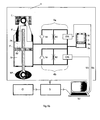
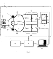
- Figs. 1a , 1b , 1c and 2 show a schematic diagram of three embodiments of the damper device designed according to claim 1. The parts common to all are described below.
- the damper device 1 is designed to damp the movement between a fixed part C and a moving part MP of a vehicle, for example a car, a motorcycle, a snowmobile or an ATV.
- the fixed part is, for example, a part of the vehicle chassis whilst the moving part may be a wheel, a ski, a runner or a rotatable handlebar.
- the damper device 1 comprises a part/damper body 2 which is sealed off from the surroundings and the internal volume of which is filled with damping medium and divided into two damper chambers 2a, 2b separated from one another by an element 5 forming a seal against the damper body.
- the sealing element 5 moves with a stroke predetermined by reciprocal movements of the vehicle parts C, MP. Under the reciprocating movements of the element 5 a high pressure is generated on the side in which the damping medium is compressed and a low pressure is generated on the side on which the damping medium expands.
- the damper chambers 2a, 2b therefore work alternately with a high or low pressure as their volume diminishes or increases.
- a valve and connecting arrangement 4a, 4b/4c which comprises at least one valve and a number of flow ducts, couples each damper chamber 2a, 2b to a pressurizing element 3 common to both of the chambers. That is to say the flow ducts are coupled both to each of the damper chambers 2a, 2b and to the pressurizing element 3, and the flow between respective parts is adjusted by the valves.
- the pressurizing element may take the form of a vessel 3a, the interior of which is divided by a floating piston 3b, which is subjected to a pressure generated, for example, by gas 3c or a mechanical pressure element such as a spring 3c', Fig. 1b .
- the floating piston may also be replaced by a pressurized rubber bladder or the like.
- the placing of the pressurizing element serves to control the valve and connecting arrangement 4a, 4b/4c, so that pressurized damping medium is always coupled to the low-pressure chamber 2a/2b.
- the pressure in the low-pressure chamber 2a/2b is therefore always positive, that is to say greater than zero, and cavitation can be prevented.
- This valve and connecting arrangement 4a, 4b/4c also controls the entire damping force characteristic of the damper 1 by adjusting the flow through this.
- the adjustment is made either via a microprocessor control unit SU, which emits a continuous electrical signal Ua, Ub, or via an electrical, mechanical or hydraulic unit 4c, which delivers a discrete predetermined signal or a specific flow. Since the valve and connecting arrangements 4a, 4b/4c are entirely separated from one another by the sealing element 5, the flow in both stroke directions can be adjusted quite independently of one another.
- Sensors S fitted to the vehicle register both ambient characteristics O, for example the state of the road, unevenness etc., and the status of the damper device 1, for example stroke length and pressure in each chamber 2a, 2b.
- Sensors such as accelerometers, pressure sensors, height sensors and angle sensors, for example, can be used to measure ambient characteristics and characteristics of the vehicle.
- the sensors S supply the control unit SU with status information which is then converted by the pre-programmed microprocessor into a suitable output signal Ua, Ub for controlling the continuously controlled valve and connecting arrangements 4a, 4b.
- a suitable output signal Ua, Ub is adjusted to provide precisely the optimum damping for the forthcoming events inferred.
- valve and connecting arrangements 4a, 4b, 4c are entirely separated from one another, it is possible in the case of rapid strokes and swift changes in position to send the output signals Ua, Ub to the respective valve and connecting arrangement 4a, 4b whilst the current stroke is still in progress.
- the time lag that occurs before the respective separately continuously controlled valve unit has adjusted to the required position consequently affects neither the functioning nor the characteristic of the damper.
- the positive pressure build-up in the low-pressure chamber of the damper means that cavitation cannot occur in the damper, which also means that damping in both stroke directions can be optimized independently of one another.
- the continuously controlled valve and connecting arrangement 4a, 4b comprises a number of ducts in conjunction with three valve units; a continuously adjustable and electrically controlled main valve CES, a non-return valve SV and a separate valve, a so-called bleed valve BV.
- the non-return valve SV is designed so that the pressurizing element 3 is always coupled to the low-pressure side of the damper.
- the bleed valve BV is designed so that the damping medium passes via said valve in the case of small strokes or slow movements in which the forces are not so great that main valve CES opens.
- the bleed valve BV therefore works in parallel with the main valve CES but in the case of large damping medium flows the flow resistance in the bleed valve BV is so great that the damping medium instead flows through the significantly larger flow ducts of the main valve CES.
- the bleed valve BV may be located outside the damper chamber (see Fig. 1a ), for example it may be located in the same outer housing 7, 15 (see Fig. 3a and 4 ) as that in which the main valves CES are fitted.
- a separate bleed valve BV may also be located directly in the part 5, 5', which separates the part 2 forming an external seal into two chambers 2a, 2b (see Fig. 1b and 4 ).
- the flow which the bleed valve BV allows to pass through may be either predetermined or adjustable.
- the adjustment can be achieved, for example, by exchanging flow-limiting parts, such as shims, or by a separate externally actuatable body which is located in the duct, the position of which determines the flow.
- the position can be adjusted manually, electrically, hydraulically, pneumatically or magnetically, for example.
- the part 2 forming an external seal is a damping cylinder.
- the damping cylinder 2 is divided by a piston 5 into a compression chamber 2a and a return chamber 2b.
- the piston is fastened to a piston rod 6, which may extend from one or both sides of the piston.
- Fig. 1b The embodiment with a piston rod passing right through is shown in Fig. 1b .
- the pressurizing element 3 does not need to take up the damping medium, which in an embodiment having a piston rod that does not pass right through is pushed in front of the piston owing to the displacement of the piston rod.
- the pressurizing element 3 can therefore be designed with smaller dimensions and adapted to only take up the variations in volume that occur in the event of temperature changes.
- the damper device 1 is fixed at one end to a vehicle chassis C, on a car, a motorcycle, a snowmobile or an ATV, for example, and at the other end is fixed via the piston rod 6', 6 to a moving part of the vehicle, such as a wheel or a ski MP, for example.
- Fig. 1c shows an embodiment comparable with Figs. 1a and 1b , but one of the continuously electrically controlled valves is replaced by a valve unit, which comprises a non-return valve SV, a bleed valve BV and a discretely adjustable valve Vr.
- This discrete valve Vr may be embodied in a number of different ways, for example by a control unit programmed with a number of predetermined signal values or by a purely mechanical adjustment of the flow aperture through the valve. Making this valve Vr non- microprocessor-controlled affords a less expensive solution.
- the damper device takes the form of a previously known vane damper having an outer housing 2 fixed to a vehicle chassis C and divided into two damper chambers 2a, 2b by an arm 5".
- the vane damper is preferably used as a control damper in which the arm 5" rotates about its one end 5a" and is at the same end 5a" also coupled to a steering device MP, not shown.
- the vane damper 1" damps the movement and accidents can be avoided.
- the valve units 4a, 4b are coupled to both of the chambers 2a and 2b and to the pressurizing element 3 in the same way as in the embodiments described above.
- the vane damper can also be used to absorb the forces between the chassis and the wheel of a vehicle.
- Fig. 3a shows a front fork with an electrically adjustable damping according to the idea of the invention.
- the front fork has a piston rod 6 working with a solid piston 5 in an damper chamber 2.
- the damper is pressurized by the pressurizing element 3 arranged in the bottom piece 7 of the front fork.
- the valve units 4a, 4b are also fitted in the same bottom piece 7.
- the valve units 4a, 4b comprise a non-return valve function and the electrically controlled variable valve CES.
- the leakage flow that occurs at low speeds is adjusted via two separate bleed valves 10a, 10b, one for the return stroke and one for the compression stroke.
- the location of the bleed valve 10a, 10b is shown more precisely in Fig.
- the hydraulic oil flows out through holes 8 in the upper part of the damping cylinder 2 and in via a flow duct between the outer leg 9 and the damping cylinder 2 into the return valve unit 4a.
- the flow through valve unit 4a is adjusted via the signal Ua from the control unit SU.
- the space 11 between the valve units 4a, 4b is pressurized by the pressurizing element 3 and the damping medium that is allowed to pass through the valve unit 4a is therefore also pressurized before flowing via the non-return valve function of the other valve unit 4b back into the damper chamber 2.
- the damping medium flows via the line 12 to and through the compression valve unit 4b controlled via the signal Ub.
- the medium then passes through the pressurized space 11 between the valve units before passing through the non-return valve function in the valve unit 4a to be led into the flow duct between the outer leg 9 and the damping cylinder 2, in order to finally pressurize the compression side of the piston 5.
- Fig. 4 shows yet another front fork, the piston rod 6 this time being fastened to the bottom piece 13.
- the damping cylinder 2 is arranged at the upper end of the front fork and a further cylinder 14 is located outside this.
- These two cylinders 2, 14 together with the head 15 form a unit 16, which also comprises the valve units 4a, 4b.
- the valve units 4a, 4b are located placed parallel with one another in turned recesses in the head 15 and are coupled to the pressurizing element 3 via a flow duct 16.
- the valve units 4a, 4b are, here too, controlled by the control unit SU, which sends the signals Ua and Ub to the main valve CES.
- the valve units 4a, 4b work on the same principle as in previous embodiments.
- the piston 5, which is fastened to the piston rod 6, may be solid or designed to allow a certain flow to pass through. If a certain flow is allowed through the piston 5, the external valve BV may be of smaller dimensions than in the case of a solid piston 5.
Landscapes
- Engineering & Computer Science (AREA)
- General Engineering & Computer Science (AREA)
- Mechanical Engineering (AREA)
- Fluid-Damping Devices (AREA)
- Vehicle Body Suspensions (AREA)
Claims (14)
- Dämpfervorrichtung für ein Fahrzeug, die einen mit Dämpfungsmedium gefüllten Dämpferkörper (2) umfasst, in dem ein Element (5, 5'), das eine Dichtung am Dämpferkörper bildet, den Dämpferkörper in zwei Kammern (2a, 2b) teilt, in denen abwechselnd Hoch- und Niedrigdruck herrschen, eine oder mehrere Ventil- und Verbindungsanordnungen (4a, 4b, 4c), die mindestens ein Ventil und eine Anzahl von Strömungskanälen umfassen, wobei entsprechende Ventile und Strömungskanäle der Ventil- und Verbindungsanordnung (4a, 4b, 4c) mit sowohl entsprechenden Dämpferkammern (2a, 2b) als auch einem Druckbeaufschlagungselement (3), das beiden Kammern gemein ist, gekoppelt sind, so dass sogar in der Kammer (2a/2b), in der ein Niedrigdruck herrscht, stets ein positiver Druck anliegt, wobei die Ventil- und Verbindungsanordnungen (4a, 4b, 4c) ein Rückschlagventil (SV) und ein oder mehrere Ablassventile (BV, 10a, 10b) umfassen, wobei das Rückschlagventil (SV) derart gestaltet ist, dass das Druckbeaufschlagungselement (3) stets an die Niedrigdruckseite des Dämpfers gekoppelt ist, dadurch gekennzeichnet, dass die Ventil- und Verbindungsanordnungen (4a, 4b, 4c) ferner ein kontinuierlich elektrisch gesteuertes Hauptventil (CES (Continuously Controlled Electronic Suspension)) umfassen, das zwischen entsprechenden Dämpferkammern (2a, 2b) und dem Druckbeaufschlagungselement (3) parallel mit dem Rückschlagventil (SV) gekoppelt ist.
- Dämpfervorrichtung nach Anspruch 1, ferner eine Mikroprozessorsteuereinheit (SU) umfassend, die mit der einen oder den mehreren Ventil- und Verbindungsanordnungen (4a, 4b, 4c) gekoppelt ist.
- Dämpfervorrichtung nach Anspruch 1, ferner eine elektrische, mechanische oder hydraulische Einheit (4c) umfassend, wobei ein Strom durch das eine oder die mehreren Ventil- und Verbindungsanordnungen (4a, 4b, 4c) über die elektrische, mechanische oder hydraulische Einheit (4c) justiert wird.
- Dämpfervorrichtung nach einem der vorhergehenden Ansprüche, wobei der Strom durch das Ablassventil / die Ablassventile (BV, 10a, 10b) getrennt vom elektrisch gesteuerten Hauptventil (CES) justiert werden kann.
- Dämpfervorrichtung nach einem der vorhergehenden Ansprüche 1 bis 3, wobei der Strom, dessen Durchströmen das Ablassventil / die Ablassventile (BV, 10a, 10b) gestattet/gestatten, vorbestimmt ist.
- Dämpfervorrichtung nach Anspruch 4, dadurch gekennzeichnet, dass das Justieren des Ablassventils / der Ablassventile (BV, 10a, 10b) durch Austausch von Strömungsbegrenzungsteilen, wie beispielsweise Abstandsscheiben, erreicht wird.
- Dämpfervorrichtung nach Anspruch 4, dadurch gekennzeichnet, dass das Justieren des Ablassventils / der Ablassventile (BV, 10a, 10b) über einen separaten, von außen zu betätigenden Körper erreicht wird, dessen Position den Strom bestimmt.
- Dämpfervorrichtung nach einem der vorhergehenden Ansprüche, dadurch gekennzeichnet, dass die Ventil- und Verbindungsanordnungen (4a, 4b/4c) angrenzend aneinander in einem gemeinsamen Gehäuse (7, 15) angeordnet sind, das auch eine Verbindung mit der Druckbeaufschlagungsvorrichtung (3) umfasst.
- Dämpfervorrichtung nach Anspruch 8, dadurch gekennzeichnet, dass das Ablassventil / die Ablassventile (BV, 10a, 10b) parallel zum elektrisch gesteuerten Hauptventil (CES) ebenfalls im gemeinsamen Gehäuse (7, 15) angeordnet ist/sind.
- Dämpfervorrichtung nach einem der vorhergehenden Ansprüche, dadurch gekennzeichnet, dass ein Ablassventil (BV, 10a, 10b) direkt im Element/Kolben/Arm (5, 5', 5") angeordnet ist, das/der den Teil (2), der eine äußere Abdichtung bildet, in zwei Kammern (2a, 2b) teilt.
- Dämpfervorrichtung nach einem der vorhergehenden Ansprüche, dadurch gekennzeichnet, dass der Dämpferkörper (2) die Form eines Zylinders einnimmt, der durch einen Kolben (5'), der an einer Kolbenstange (6', 6") befestigt ist, in eine Verdichtungskammer (2a) und eine Rücklaufkammer (2b) geteilt ist.
- Dämpfervorrichtung nach einem der vorhergehenden Ansprüche, dadurch gekennzeichnet, dass der Dämpferkörper (2) im Inneren einer Vordergabel angeordnet ist.
- Dämpfervorrichtung nach einem der Ansprüche 1 bis 7, dadurch gekennzeichnet, dass der Dämpfer die Form eines Drehflügeldämpfers einnimmt, wobei der Teil (2), der eine äußere Abdichtung bildet, ein Außengehäuse (2") ist, das durch einen Arm (5") geteilt ist, der sich um eines seiner Enden drehen kann.
- Dämpfervorrichtung nach einem der Ansprüche 1 bis 7 oder 13, dadurch gekennzeichnet, dass das eine oder die mehreren Ablassventile (BV, 10a, 10b) direkt im Element/Kolben/ Arm (5, 5', 5") angeordnet sind, das/der den Teil (2), der eine äußere Abdichtung bildet, in zwei Kammern (2a, 2b) teilt.
Applications Claiming Priority (2)
| Application Number | Priority Date | Filing Date | Title |
|---|---|---|---|
| SE0600403A SE531618C2 (sv) | 2006-02-23 | 2006-02-23 | Elektrisk styrd trycksatt dämpare |
| PCT/SE2007/000168 WO2007097699A1 (en) | 2006-02-23 | 2007-02-23 | Electronically controlled pressurised damper |
Publications (3)
| Publication Number | Publication Date |
|---|---|
| EP1987268A1 EP1987268A1 (de) | 2008-11-05 |
| EP1987268A4 EP1987268A4 (de) | 2011-07-27 |
| EP1987268B1 true EP1987268B1 (de) | 2014-06-18 |
Family
ID=38437646
Family Applications (1)
| Application Number | Title | Priority Date | Filing Date |
|---|---|---|---|
| EP07709378.9A Active EP1987268B1 (de) | 2006-02-23 | 2007-02-23 | Elektronisch gesteuerter druckbeaufschlagter dämpfer |
Country Status (4)
| Country | Link |
|---|---|
| US (1) | US8978847B2 (de) |
| EP (1) | EP1987268B1 (de) |
| SE (1) | SE531618C2 (de) |
| WO (1) | WO2007097699A1 (de) |
Cited By (3)
| Publication number | Priority date | Publication date | Assignee | Title |
|---|---|---|---|---|
| US11970034B2 (en) | 2018-05-07 | 2024-04-30 | E:Fs Techhub Gmbh | Damper unit for a chassis of a vehicle with levelling |
| US12090807B2 (en) | 2019-05-14 | 2024-09-17 | Tenneco Automotive Operating Company, Inc. | Scalable damper |
| WO2025008138A1 (de) * | 2023-07-05 | 2025-01-09 | Volkswagen Aktiengesellschaft | STEUERVORRICHTUNG ZUM ANSTEUERN EINES STOßDÄMPFERS EINES KRAFTFAHRZEUGS, COMPUTERPROGRAMMPRODUKT UND KRAFTFAHRZEUG |
Families Citing this family (19)
| Publication number | Priority date | Publication date | Assignee | Title |
|---|---|---|---|---|
| US7946163B2 (en) | 2007-04-02 | 2011-05-24 | Penske Racing Shocks | Methods and apparatus for developing a vehicle suspension |
| US8403115B2 (en) | 2008-01-11 | 2013-03-26 | Penske Racing Shocks | Dual rate gas spring shock absorber |
| US9403667B2 (en) | 2011-03-18 | 2016-08-02 | The Raymond Corporation | Dynamic vibration control systems and methods for industrial lift trucks |
| US8731785B2 (en) | 2011-03-18 | 2014-05-20 | The Raymond Corporation | Dynamic stability control systems and methods for industrial lift trucks |
| US8763990B2 (en) | 2012-03-20 | 2014-07-01 | The Raymond Corporation | Turn stability systems and methods for lift trucks |
| US9481221B2 (en) | 2013-01-08 | 2016-11-01 | Tenneco Automotive Operating Company Inc. | Passive and active suspension with optimization of energy usage |
| US9302893B2 (en) | 2013-02-07 | 2016-04-05 | The Raymond Corporation | Vibration control systems and methods for industrial lift trucks |
| US9002557B2 (en) | 2013-03-14 | 2015-04-07 | The Raymond Corporation | Systems and methods for maintaining an industrial lift truck within defined bounds |
| US9863450B1 (en) * | 2014-04-16 | 2018-01-09 | Rockwell Collins, Inc. | Hydro-mechanical device with preloaded flow regulating assembly |
| JP6349182B2 (ja) * | 2014-07-22 | 2018-06-27 | Kyb株式会社 | ダンパ制御装置 |
| KR102429549B1 (ko) * | 2015-05-18 | 2022-08-05 | 주식회사 만도 | 전자제어 현가장치 및 그의 감쇠력 제어 방법 |
| US10434835B2 (en) | 2016-02-24 | 2019-10-08 | Tenneco Automotive Operating Company Inc. | Monotube active suspension system having different system layouts for controlling pump flow distribution |
| KR101907105B1 (ko) | 2016-07-18 | 2018-10-11 | 주식회사 만도 | 능동형 현가 시스템의 댐퍼 장치 |
| US10358010B2 (en) | 2017-06-05 | 2019-07-23 | Tenneco Automotive Operating Company Inc. | Interlinked active suspension |
| CN107939893B (zh) * | 2017-12-29 | 2024-03-15 | 深圳职业技术学院 | 主动悬架系统、减振器以及减振部件 |
| EP3569890B1 (de) | 2018-05-14 | 2024-06-26 | DRiV Automotive Inc. | Stossdämpfer und verfahren zur steuerung eines dämpfungsflusses in einem stossdämpfer und verwendung zweier elektrischen gesteuerten ventile zur steuerung eines dämpfungsflusses in einem stossdämpfer |
| IT201900015590A1 (it) * | 2019-09-04 | 2021-03-04 | Cnh Ind Italia Spa | Disposizione idraulica di sospensione per un veicolo da lavoro |
| EP4147889A1 (de) * | 2021-09-08 | 2023-03-15 | Volvo Car Corporation | Dämpfersystem und verfahren zur veränderung der bodenfreiheit eines fahrzeugs |
| DE102023115399B4 (de) * | 2023-06-13 | 2026-03-19 | Dr. Ing. H.C. F. Porsche Aktiengesellschaft | Verfahren zum Betrieb eines Dämpfersystems eines Fahrzeugs |
Family Cites Families (11)
| Publication number | Priority date | Publication date | Assignee | Title |
|---|---|---|---|---|
| SE443622B (sv) | 1984-04-04 | 1986-03-03 | Rolf Blixt | For stotdempare avsedd anordning for att mojliggora variation av dempformagan |
| DE3414258A1 (de) * | 1984-04-14 | 1985-10-24 | Robert Bosch Gmbh, 7000 Stuttgart | Vorrichtung zum steuern der federhaerte eines fahrzeugs i |
| DE3414257C2 (de) * | 1984-04-14 | 1993-12-02 | Bosch Gmbh Robert | Federelement mit veränderbarer Härte für Fahrzeuge |
| SE466514B (sv) * | 1988-02-22 | 1992-02-24 | Oehlins Racing Ab | Anordning foer att i en stoetdaempare aastadkomma olika med styrningar bestaembara daempkaraktaerer oberoende av variation i parametrar som straevar efter att foeraendra instaellda daempkrafter paa ooenskat saett |
| US5222759A (en) * | 1990-02-27 | 1993-06-29 | Robert Bosch Gmbh | Apparatus for active control of body motions in motor vehicles |
| SE511320C2 (sv) * | 1993-04-23 | 1999-09-13 | Oehlins Racing Ab | Anordning vid stötdämpare som använder hysteresisfunktion för bestämning av dämpkraftsvariationen |
| US5586627A (en) * | 1993-05-20 | 1996-12-24 | Tokico, Ltd. | Hydraulic shock absorber of damping force adjustable type |
| US5570286A (en) * | 1993-12-23 | 1996-10-29 | Lord Corporation | Regenerative system including an energy transformer which requires no external power source to drive same |
| FR2722265B1 (fr) * | 1994-07-06 | 1996-08-23 | Gec Alsthom Transport Sa | Amortisseur semi-actif |
| FR2750752B1 (fr) * | 1996-07-05 | 2002-03-01 | Gec Alsthom Transport Sa | Amortisseur semi-actif a controle continu en effort |
| GB2378231B (en) | 1999-05-25 | 2003-03-26 | Tenneco Automotive Inc | Damper with externally mounted semi-active system |
-
2006
- 2006-02-23 SE SE0600403A patent/SE531618C2/sv unknown
-
2007
- 2007-02-23 EP EP07709378.9A patent/EP1987268B1/de active Active
- 2007-02-23 US US12/280,464 patent/US8978847B2/en active Active
- 2007-02-23 WO PCT/SE2007/000168 patent/WO2007097699A1/en not_active Ceased
Cited By (3)
| Publication number | Priority date | Publication date | Assignee | Title |
|---|---|---|---|---|
| US11970034B2 (en) | 2018-05-07 | 2024-04-30 | E:Fs Techhub Gmbh | Damper unit for a chassis of a vehicle with levelling |
| US12090807B2 (en) | 2019-05-14 | 2024-09-17 | Tenneco Automotive Operating Company, Inc. | Scalable damper |
| WO2025008138A1 (de) * | 2023-07-05 | 2025-01-09 | Volkswagen Aktiengesellschaft | STEUERVORRICHTUNG ZUM ANSTEUERN EINES STOßDÄMPFERS EINES KRAFTFAHRZEUGS, COMPUTERPROGRAMMPRODUKT UND KRAFTFAHRZEUG |
Also Published As
| Publication number | Publication date |
|---|---|
| US20090166989A1 (en) | 2009-07-02 |
| SE0600403L (sv) | 2007-08-24 |
| EP1987268A4 (de) | 2011-07-27 |
| SE531618C2 (sv) | 2009-06-09 |
| EP1987268A1 (de) | 2008-11-05 |
| WO2007097699A1 (en) | 2007-08-30 |
| US8978847B2 (en) | 2015-03-17 |
Similar Documents
| Publication | Publication Date | Title |
|---|---|---|
| EP1987268B1 (de) | Elektronisch gesteuerter druckbeaufschlagter dämpfer | |
| US12504053B2 (en) | Position sensitive suspension damping with an active valve | |
| US5082309A (en) | Suspension system for vehicles | |
| JP4587089B2 (ja) | 減衰力調整式油圧緩衝器 | |
| EP2410203B1 (de) | Aufhängungsdämpfer mit fernbetriebenem Ventil | |
| US9239090B2 (en) | Suspension damper with remotely-operable valve | |
| US11511592B2 (en) | Suspension system for a vehicle | |
| JP4985984B2 (ja) | 減衰力調整式緩衝器 | |
| US20120305348A1 (en) | Suspension apparatus | |
| US6332622B1 (en) | Suspension apparatus having two interconnected shock absorbers | |
| EP2017100A1 (de) | Fahrzeugrollensteuerungssystem | |
| US20080238004A1 (en) | System for controlling damping and roll and pitch body movements of a motor vehicle, having adjustable hydraulic actuators | |
| JP4828325B2 (ja) | 緩衝器の制御装置 | |
| ATE280051T1 (de) | Fahrzeugaufhängungssystem | |
| JP5136789B2 (ja) | 緩衝器 | |
| JPH084818A (ja) | 減衰力調整式油圧緩衝器 | |
| JP2006077789A (ja) | 可変減衰力ダンパー | |
| US12522039B2 (en) | Suspension system with proportional pressure accumulator | |
| WO2016199667A1 (ja) | 緩衝器 | |
| EP2126403B1 (de) | Verfahren und anpassung von dämpfeigenschaften bei einem stossdämpfer | |
| JPH06330977A (ja) | 減衰力調整式油圧緩衝器 | |
| US11719305B2 (en) | Balanced continuously semi-active damper | |
| US6450286B1 (en) | Rack and pinion power steering system with variable damping characteristics | |
| JP3265523B2 (ja) | 減衰力調整式油圧緩衝器 | |
| CN115450968B (zh) | 一种主动式液压升降控制系统 |
Legal Events
| Date | Code | Title | Description |
|---|---|---|---|
| PUAI | Public reference made under article 153(3) epc to a published international application that has entered the european phase |
Free format text: ORIGINAL CODE: 0009012 |
|
| 17P | Request for examination filed |
Effective date: 20080819 |
|
| AK | Designated contracting states |
Kind code of ref document: A1 Designated state(s): AT BE BG CH CY CZ DE DK EE ES FI FR GB GR HU IE IS IT LI LT LU LV MC NL PL PT RO SE SI SK TR |
|
| A4 | Supplementary search report drawn up and despatched |
Effective date: 20110627 |
|
| DAX | Request for extension of the european patent (deleted) | ||
| REG | Reference to a national code |
Ref country code: DE Ref legal event code: R079 Ref document number: 602007037198 Country of ref document: DE Free format text: PREVIOUS MAIN CLASS: F16F0009460000 Ipc: B60G0017080000 |
|
| GRAP | Despatch of communication of intention to grant a patent |
Free format text: ORIGINAL CODE: EPIDOSNIGR1 |
|
| RIC1 | Information provided on ipc code assigned before grant |
Ipc: F16F 9/46 20060101ALI20131209BHEP Ipc: B60G 17/08 20060101AFI20131209BHEP Ipc: B60G 17/04 20060101ALI20131209BHEP |
|
| INTG | Intention to grant announced |
Effective date: 20140108 |
|
| GRAS | Grant fee paid |
Free format text: ORIGINAL CODE: EPIDOSNIGR3 |
|
| GRAA | (expected) grant |
Free format text: ORIGINAL CODE: 0009210 |
|
| AK | Designated contracting states |
Kind code of ref document: B1 Designated state(s): AT BE BG CH CY CZ DE DK EE ES FI FR GB GR HU IE IS IT LI LT LU LV MC NL PL PT RO SE SI SK TR |
|
| REG | Reference to a national code |
Ref country code: GB Ref legal event code: FG4D |
|
| REG | Reference to a national code |
Ref country code: CH Ref legal event code: EP |
|
| REG | Reference to a national code |
Ref country code: AT Ref legal event code: REF Ref document number: 673118 Country of ref document: AT Kind code of ref document: T Effective date: 20140715 |
|
| REG | Reference to a national code |
Ref country code: IE Ref legal event code: FG4D |
|
| REG | Reference to a national code |
Ref country code: DE Ref legal event code: R096 Ref document number: 602007037198 Country of ref document: DE Effective date: 20140731 |
|
| PG25 | Lapsed in a contracting state [announced via postgrant information from national office to epo] |
Ref country code: CY Free format text: LAPSE BECAUSE OF FAILURE TO SUBMIT A TRANSLATION OF THE DESCRIPTION OR TO PAY THE FEE WITHIN THE PRESCRIBED TIME-LIMIT Effective date: 20140618 Ref country code: LT Free format text: LAPSE BECAUSE OF FAILURE TO SUBMIT A TRANSLATION OF THE DESCRIPTION OR TO PAY THE FEE WITHIN THE PRESCRIBED TIME-LIMIT Effective date: 20140618 Ref country code: FI Free format text: LAPSE BECAUSE OF FAILURE TO SUBMIT A TRANSLATION OF THE DESCRIPTION OR TO PAY THE FEE WITHIN THE PRESCRIBED TIME-LIMIT Effective date: 20140618 Ref country code: GR Free format text: LAPSE BECAUSE OF FAILURE TO SUBMIT A TRANSLATION OF THE DESCRIPTION OR TO PAY THE FEE WITHIN THE PRESCRIBED TIME-LIMIT Effective date: 20140919 |
|
| REG | Reference to a national code |
Ref country code: NL Ref legal event code: VDEP Effective date: 20140618 |
|
| REG | Reference to a national code |
Ref country code: AT Ref legal event code: MK05 Ref document number: 673118 Country of ref document: AT Kind code of ref document: T Effective date: 20140618 |
|
| REG | Reference to a national code |
Ref country code: LT Ref legal event code: MG4D |
|
| PG25 | Lapsed in a contracting state [announced via postgrant information from national office to epo] |
Ref country code: LV Free format text: LAPSE BECAUSE OF FAILURE TO SUBMIT A TRANSLATION OF THE DESCRIPTION OR TO PAY THE FEE WITHIN THE PRESCRIBED TIME-LIMIT Effective date: 20140618 Ref country code: SE Free format text: LAPSE BECAUSE OF FAILURE TO SUBMIT A TRANSLATION OF THE DESCRIPTION OR TO PAY THE FEE WITHIN THE PRESCRIBED TIME-LIMIT Effective date: 20140618 |
|
| PG25 | Lapsed in a contracting state [announced via postgrant information from national office to epo] |
Ref country code: SK Free format text: LAPSE BECAUSE OF FAILURE TO SUBMIT A TRANSLATION OF THE DESCRIPTION OR TO PAY THE FEE WITHIN THE PRESCRIBED TIME-LIMIT Effective date: 20140618 Ref country code: RO Free format text: LAPSE BECAUSE OF FAILURE TO SUBMIT A TRANSLATION OF THE DESCRIPTION OR TO PAY THE FEE WITHIN THE PRESCRIBED TIME-LIMIT Effective date: 20140618 Ref country code: ES Free format text: LAPSE BECAUSE OF FAILURE TO SUBMIT A TRANSLATION OF THE DESCRIPTION OR TO PAY THE FEE WITHIN THE PRESCRIBED TIME-LIMIT Effective date: 20140618 Ref country code: EE Free format text: LAPSE BECAUSE OF FAILURE TO SUBMIT A TRANSLATION OF THE DESCRIPTION OR TO PAY THE FEE WITHIN THE PRESCRIBED TIME-LIMIT Effective date: 20140618 Ref country code: PT Free format text: LAPSE BECAUSE OF FAILURE TO SUBMIT A TRANSLATION OF THE DESCRIPTION OR TO PAY THE FEE WITHIN THE PRESCRIBED TIME-LIMIT Effective date: 20141020 Ref country code: CZ Free format text: LAPSE BECAUSE OF FAILURE TO SUBMIT A TRANSLATION OF THE DESCRIPTION OR TO PAY THE FEE WITHIN THE PRESCRIBED TIME-LIMIT Effective date: 20140618 |
|
| PG25 | Lapsed in a contracting state [announced via postgrant information from national office to epo] |
Ref country code: IS Free format text: LAPSE BECAUSE OF FAILURE TO SUBMIT A TRANSLATION OF THE DESCRIPTION OR TO PAY THE FEE WITHIN THE PRESCRIBED TIME-LIMIT Effective date: 20141018 Ref country code: AT Free format text: LAPSE BECAUSE OF FAILURE TO SUBMIT A TRANSLATION OF THE DESCRIPTION OR TO PAY THE FEE WITHIN THE PRESCRIBED TIME-LIMIT Effective date: 20140618 Ref country code: NL Free format text: LAPSE BECAUSE OF FAILURE TO SUBMIT A TRANSLATION OF THE DESCRIPTION OR TO PAY THE FEE WITHIN THE PRESCRIBED TIME-LIMIT Effective date: 20140618 Ref country code: PL Free format text: LAPSE BECAUSE OF FAILURE TO SUBMIT A TRANSLATION OF THE DESCRIPTION OR TO PAY THE FEE WITHIN THE PRESCRIBED TIME-LIMIT Effective date: 20140618 |
|
| REG | Reference to a national code |
Ref country code: DE Ref legal event code: R097 Ref document number: 602007037198 Country of ref document: DE |
|
| PLBE | No opposition filed within time limit |
Free format text: ORIGINAL CODE: 0009261 |
|
| STAA | Information on the status of an ep patent application or granted ep patent |
Free format text: STATUS: NO OPPOSITION FILED WITHIN TIME LIMIT |
|
| PG25 | Lapsed in a contracting state [announced via postgrant information from national office to epo] |
Ref country code: DK Free format text: LAPSE BECAUSE OF FAILURE TO SUBMIT A TRANSLATION OF THE DESCRIPTION OR TO PAY THE FEE WITHIN THE PRESCRIBED TIME-LIMIT Effective date: 20140618 |
|
| 26N | No opposition filed |
Effective date: 20150319 |
|
| PG25 | Lapsed in a contracting state [announced via postgrant information from national office to epo] |
Ref country code: BE Free format text: LAPSE BECAUSE OF FAILURE TO SUBMIT A TRANSLATION OF THE DESCRIPTION OR TO PAY THE FEE WITHIN THE PRESCRIBED TIME-LIMIT Effective date: 20140618 |
|
| PG25 | Lapsed in a contracting state [announced via postgrant information from national office to epo] |
Ref country code: SI Free format text: LAPSE BECAUSE OF FAILURE TO SUBMIT A TRANSLATION OF THE DESCRIPTION OR TO PAY THE FEE WITHIN THE PRESCRIBED TIME-LIMIT Effective date: 20140618 |
|
| PG25 | Lapsed in a contracting state [announced via postgrant information from national office to epo] |
Ref country code: LU Free format text: LAPSE BECAUSE OF FAILURE TO SUBMIT A TRANSLATION OF THE DESCRIPTION OR TO PAY THE FEE WITHIN THE PRESCRIBED TIME-LIMIT Effective date: 20150223 |
|
| REG | Reference to a national code |
Ref country code: CH Ref legal event code: PL |
|
| PG25 | Lapsed in a contracting state [announced via postgrant information from national office to epo] |
Ref country code: MC Free format text: LAPSE BECAUSE OF FAILURE TO SUBMIT A TRANSLATION OF THE DESCRIPTION OR TO PAY THE FEE WITHIN THE PRESCRIBED TIME-LIMIT Effective date: 20140618 Ref country code: LI Free format text: LAPSE BECAUSE OF NON-PAYMENT OF DUE FEES Effective date: 20150228 Ref country code: CH Free format text: LAPSE BECAUSE OF NON-PAYMENT OF DUE FEES Effective date: 20150228 |
|
| REG | Reference to a national code |
Ref country code: IE Ref legal event code: MM4A |
|
| PG25 | Lapsed in a contracting state [announced via postgrant information from national office to epo] |
Ref country code: IE Free format text: LAPSE BECAUSE OF NON-PAYMENT OF DUE FEES Effective date: 20150223 |
|
| REG | Reference to a national code |
Ref country code: FR Ref legal event code: PLFP Year of fee payment: 10 |
|
| REG | Reference to a national code |
Ref country code: FR Ref legal event code: PLFP Year of fee payment: 11 |
|
| PG25 | Lapsed in a contracting state [announced via postgrant information from national office to epo] |
Ref country code: HU Free format text: LAPSE BECAUSE OF FAILURE TO SUBMIT A TRANSLATION OF THE DESCRIPTION OR TO PAY THE FEE WITHIN THE PRESCRIBED TIME-LIMIT; INVALID AB INITIO Effective date: 20070223 Ref country code: BG Free format text: LAPSE BECAUSE OF FAILURE TO SUBMIT A TRANSLATION OF THE DESCRIPTION OR TO PAY THE FEE WITHIN THE PRESCRIBED TIME-LIMIT Effective date: 20140618 |
|
| PG25 | Lapsed in a contracting state [announced via postgrant information from national office to epo] |
Ref country code: TR Free format text: LAPSE BECAUSE OF FAILURE TO SUBMIT A TRANSLATION OF THE DESCRIPTION OR TO PAY THE FEE WITHIN THE PRESCRIBED TIME-LIMIT Effective date: 20140618 |
|
| REG | Reference to a national code |
Ref country code: FR Ref legal event code: PLFP Year of fee payment: 12 |
|
| P01 | Opt-out of the competence of the unified patent court (upc) registered |
Effective date: 20230528 |
|
| REG | Reference to a national code |
Ref country code: DE Ref legal event code: R081 Ref document number: 602007037198 Country of ref document: DE Owner name: DRIV AUTOMOTIVE INC., NORTHVILLE, US Free format text: FORMER OWNER: OEHLINS RACING AB, UPPLANDS VAESBY, SE Ref country code: DE Ref legal event code: R081 Ref document number: 602007037198 Country of ref document: DE Owner name: ADVANCED SUSPENSION TECHNOLOGY LLC (N.D.GES.D., US Free format text: FORMER OWNER: OEHLINS RACING AB, UPPLANDS VAESBY, SE |
|
| REG | Reference to a national code |
Ref country code: GB Ref legal event code: 732E Free format text: REGISTERED BETWEEN 20241121 AND 20241127 |
|
| REG | Reference to a national code |
Ref country code: DE Ref legal event code: R081 Ref document number: 602007037198 Country of ref document: DE Owner name: ADVANCED SUSPENSION TECHNOLOGY LLC (N.D.GES.D., US Free format text: FORMER OWNER: DRIV AUTOMOTIVE INC., NORTHVILLE, MI, US |
|
| PGFP | Annual fee paid to national office [announced via postgrant information from national office to epo] |
Ref country code: GB Payment date: 20260121 Year of fee payment: 20 |
|
| PGFP | Annual fee paid to national office [announced via postgrant information from national office to epo] |
Ref country code: DE Payment date: 20260121 Year of fee payment: 20 |
|
| PGFP | Annual fee paid to national office [announced via postgrant information from national office to epo] |
Ref country code: IT Payment date: 20260121 Year of fee payment: 20 |
|
| PGFP | Annual fee paid to national office [announced via postgrant information from national office to epo] |
Ref country code: FR Payment date: 20260121 Year of fee payment: 20 |