EP1987383B1 - Glasfaser-splittermodul - Google Patents
Glasfaser-splittermodul Download PDFInfo
- Publication number
- EP1987383B1 EP1987383B1 EP07749942.4A EP07749942A EP1987383B1 EP 1987383 B1 EP1987383 B1 EP 1987383B1 EP 07749942 A EP07749942 A EP 07749942A EP 1987383 B1 EP1987383 B1 EP 1987383B1
- Authority
- EP
- European Patent Office
- Prior art keywords
- fiber optic
- module
- chassis
- housing
- connector
- Prior art date
- Legal status (The legal status is an assumption and is not a legal conclusion. Google has not performed a legal analysis and makes no representation as to the accuracy of the status listed.)
- Not-in-force
Links
Images











Classifications
-
- G—PHYSICS
- G02—OPTICS
- G02B—OPTICAL ELEMENTS, SYSTEMS OR APPARATUS
- G02B6/00—Light guides; Structural details of arrangements comprising light guides and other optical elements, e.g. couplings
- G02B6/44—Mechanical structures for providing tensile strength and external protection for fibres, e.g. optical transmission cables
- G02B6/4439—Auxiliary devices
- G02B6/444—Systems or boxes with surplus lengths
- G02B6/4452—Distribution frames
- G02B6/44526—Panels or rackmounts covering a whole width of the frame or rack
-
- G—PHYSICS
- G02—OPTICS
- G02B—OPTICAL ELEMENTS, SYSTEMS OR APPARATUS
- G02B6/00—Light guides; Structural details of arrangements comprising light guides and other optical elements, e.g. couplings
- G02B6/44—Mechanical structures for providing tensile strength and external protection for fibres, e.g. optical transmission cables
- G02B6/4439—Auxiliary devices
- G02B6/444—Systems or boxes with surplus lengths
- G02B6/4453—Cassettes
-
- G—PHYSICS
- G02—OPTICS
- G02B—OPTICAL ELEMENTS, SYSTEMS OR APPARATUS
- G02B6/00—Light guides; Structural details of arrangements comprising light guides and other optical elements, e.g. couplings
- G02B6/24—Coupling light guides
- G02B6/26—Optical coupling means
- G02B6/28—Optical coupling means having data bus means, i.e. plural waveguides interconnected and providing an inherently bidirectional system by mixing and splitting signals
-
- G—PHYSICS
- G02—OPTICS
- G02B—OPTICAL ELEMENTS, SYSTEMS OR APPARATUS
- G02B6/00—Light guides; Structural details of arrangements comprising light guides and other optical elements, e.g. couplings
- G02B6/24—Coupling light guides
- G02B6/36—Mechanical coupling means
- G02B6/38—Mechanical coupling means having fibre to fibre mating means
- G02B6/3807—Dismountable connectors, i.e. comprising plugs
- G02B6/3887—Anchoring optical cables to connector housings, e.g. strain relief features
- G02B6/3888—Protection from over-extension or over-compression
-
- G—PHYSICS
- G02—OPTICS
- G02B—OPTICAL ELEMENTS, SYSTEMS OR APPARATUS
- G02B6/00—Light guides; Structural details of arrangements comprising light guides and other optical elements, e.g. couplings
- G02B6/24—Coupling light guides
- G02B6/36—Mechanical coupling means
- G02B6/38—Mechanical coupling means having fibre to fibre mating means
- G02B6/3807—Dismountable connectors, i.e. comprising plugs
- G02B6/3897—Connectors fixed to housings, casing, frames or circuit boards
-
- G—PHYSICS
- G02—OPTICS
- G02B—OPTICAL ELEMENTS, SYSTEMS OR APPARATUS
- G02B6/00—Light guides; Structural details of arrangements comprising light guides and other optical elements, e.g. couplings
- G02B6/44—Mechanical structures for providing tensile strength and external protection for fibres, e.g. optical transmission cables
- G02B6/4439—Auxiliary devices
- G02B6/444—Systems or boxes with surplus lengths
- G02B6/4441—Boxes
- G02B6/4446—Cable boxes, e.g. splicing boxes with two or more multi fibre cables
-
- G—PHYSICS
- G02—OPTICS
- G02B—OPTICAL ELEMENTS, SYSTEMS OR APPARATUS
- G02B6/00—Light guides; Structural details of arrangements comprising light guides and other optical elements, e.g. couplings
- G02B6/44—Mechanical structures for providing tensile strength and external protection for fibres, e.g. optical transmission cables
- G02B6/4439—Auxiliary devices
- G02B6/444—Systems or boxes with surplus lengths
- G02B6/4452—Distribution frames
-
- G—PHYSICS
- G02—OPTICS
- G02B—OPTICAL ELEMENTS, SYSTEMS OR APPARATUS
- G02B6/00—Light guides; Structural details of arrangements comprising light guides and other optical elements, e.g. couplings
- G02B6/44—Mechanical structures for providing tensile strength and external protection for fibres, e.g. optical transmission cables
- G02B6/4439—Auxiliary devices
- G02B6/444—Systems or boxes with surplus lengths
- G02B6/4453—Cassettes
- G02B6/4455—Cassettes characterised by the way of extraction or insertion of the cassette in the distribution frame, e.g. pivoting, sliding, rotating or gliding
-
- G—PHYSICS
- G02—OPTICS
- G02B—OPTICAL ELEMENTS, SYSTEMS OR APPARATUS
- G02B6/00—Light guides; Structural details of arrangements comprising light guides and other optical elements, e.g. couplings
- G02B6/44—Mechanical structures for providing tensile strength and external protection for fibres, e.g. optical transmission cables
- G02B6/4439—Auxiliary devices
- G02B6/4457—Bobbins; Reels
-
- G—PHYSICS
- G02—OPTICS
- G02B—OPTICAL ELEMENTS, SYSTEMS OR APPARATUS
- G02B6/00—Light guides; Structural details of arrangements comprising light guides and other optical elements, e.g. couplings
- G02B6/44—Mechanical structures for providing tensile strength and external protection for fibres, e.g. optical transmission cables
- G02B6/4439—Auxiliary devices
- G02B6/4471—Terminating devices ; Cable clamps
-
- G—PHYSICS
- G02—OPTICS
- G02B—OPTICAL ELEMENTS, SYSTEMS OR APPARATUS
- G02B6/00—Light guides; Structural details of arrangements comprising light guides and other optical elements, e.g. couplings
- G02B6/46—Processes or apparatus adapted for installing or repairing optical fibres or optical cables
-
- G—PHYSICS
- G02—OPTICS
- G02B—OPTICAL ELEMENTS, SYSTEMS OR APPARATUS
- G02B6/00—Light guides; Structural details of arrangements comprising light guides and other optical elements, e.g. couplings
- G02B6/24—Coupling light guides
- G02B6/36—Mechanical coupling means
- G02B6/38—Mechanical coupling means having fibre to fibre mating means
- G02B6/3807—Dismountable connectors, i.e. comprising plugs
- G02B6/3833—Details of mounting fibres in ferrules; Assembly methods; Manufacture
- G02B6/3847—Details of mounting fibres in ferrules; Assembly methods; Manufacture with means preventing fibre end damage, e.g. recessed fibre surfaces
- G02B6/3849—Details of mounting fibres in ferrules; Assembly methods; Manufacture with means preventing fibre end damage, e.g. recessed fibre surfaces using mechanical protective elements, e.g. caps, hoods, sealing membranes
Definitions
- the present invention generally relates to fiber optic telecommunications equipment. More specifically, the present invention relates to fiber optic modules and chassis for holding fiber optic modules.
- optical fibers of transmission cables In fiber optic telecommunications systems, it is common for optical fibers of transmission cables to be split into multiple strands, either by optical splitting of a signal carried by a single stranded cable or by fanning out the individual fibers of a multi-strand cable. Further, when such systems are installed, it is known to provide excess capacity in the installations to support future growth and utilization of the fibers. Often in these installations, modules including splitters or fanouts are used to provide the connection between transmission fibers and customer fibers.
- a module mounting chassis capable of mounting multiple modules may be used in such an installation Document US 6,822,874 discloses a telecommunications assembly, comprising: a chassis including a top, a bottom, a front opening, a rear opening, and first and second transverse sides extending between the front and rear openings, the chassis defining a plurality of mounting locations; a module configured to be slidably received within the chassis through the front opening at one of the mounting locations, the module removable from the chassis through the front opening; and an adapter assembly that is separate from the module, the adapter assembly defining at least one adapter, the adapter assembly configured to be slidably received within the chassis through the rear opening at one of the mounting locations, the adapter assembly removable from the chassis through the rear opening; the module including at least one connector that protrudes from the module that is adapted to be inserted into the adapter of the adapter assembly when the module is inserted into the chassis.
- chassis may accept several modules, the initial installation may only include fewer modules mounted in the chassis, or enough to serve current needs.
- These chassis may be configured with limited access to one or more sides, or may be mounted in cramped locations.
- some of these chassis may be pre-configured with the maximum capacity of transmission cables to accommodate and link to modules which may be installed in the future. Since it is desirable to have access to components within the chassis for cleaning during the installation of a new module, some provision or feature of the chassis will desirably permit a user to access and clean the connectors of these pre-connectorized and pre-installed transmission cables.
- chassis pre-connectorized and pre-installed transmission cables.
- the present invention relates to a telecommunications assembly as defined in appended claim 1 and including a chassis and a plurality of modules mounted within the chassis.
- the modules include one or more fiber optic connectors.
- Within an interior of the chassis at each mounting location are positioned corresponding fiber optic adapters. Inserting the module through a front opening of the chassis at a mounting location positions the one or more connectors of the module for insertion into and mating with the adapters of the chassis.
- the adapters within the interior of the chassis are integrally formed within a removable adapter assembly.
- the present invention further relates to a method of mounting a telecommunications module within a chassis. as defined in appended claim 12. Further features of the invention are defined in dependent claims 2-11 and 13-25.
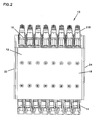
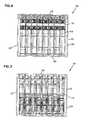
- FIGS. 1-7 illustrate a telecommunications assembly 10 that includes a telecommunications chassis 12 and a plurality of fiber optic splitter modules 14 adapted to be mounted within chassis 12.
- Fiber optic splitter modules 14 are configured to be slidably inserted within chassis 12 and be optically coupled to adapter assemblies 16 mounted within chassis 12.
- Adapter assemblies 16 mounted within chassis 12 form connection locations between connectors terminated to an incoming fiber optic cable and connectors of splitter modules 14 as will be discussed in further detail below.
- chassis 12 includes a top wall 18 and a bottom wall 20 extending between a pair of opposing transverse sidewalls, 22, 24.
- Chassis 12 includes an opening 26 through a rear side 28 of chassis 12 and an opening 30 through a front side 32 of chassis 12.
- Fiber optic splitter modules 14 are inserted into chassis 12 through front opening 30.
- Adapter assemblies 16 are inserted through and mounted adjacent rear opening 26 of chassis 12.
- Sidewalls 22, 24, each include a cut-out 34 extending from front opening 30 toward rear side 28.
- Splitter modules 14 mounted within chassis 12 are visible through cut-out 34.
- Sidewalls 22, 24 of chassis 12 also define an inset portion 36 at rear side 28 of chassis 12 to facilitate access to adapter assemblies 16.
- chassis 12 is shown with eight fiber optic splitter modules 14 mounted thereon. It should be noted that in other embodiments, the chassis may be sized to hold a larger or a smaller number of splitter modules.
- chassis 12 includes a plurality of mounting locations 38 for slidably receiving splitter modules 14.
- Each mounting location 38 defines a slot 40 adjacent top wall 18 and a slot 42 adjacent bottom wall 20 of chassis 12.
- Slots 42 adjacent bottom wall 20 are visible in FIG. 1 .
- Slots 40 adjacent top wall 18 are illustrated in FIGS. 36 and 37 .
- Slots 40, 42 extend from front 32 of chassis 12 to rear 28 of chassis 12.
- Slots 40, 42 are configured to receive mounting flanges 44, 46 of splitter modules 14 as shown in FIGS. 36 and 37 to align modules 14 with other components within chassis 12 (e.g., adapters of the adapter assemblies) to mate with pre-connectorized and/or pre-installed transmission cables.
- slots 40 defined underneath top wall 18 of chassis 12 are deeper than slots 42 defined at bottom wall 20 of chassis 12.
- the depth of slots 40, 42 are configured to accommodate the different sized flanges 44, 46 that are defined at top and bottom walls of splitter modules 14. In this manner, slots 40, 42 and mounting flanges 44, 46 of fiber optic splitter modules 14 provide a keying system to ensure that modules 14 are inserted into chassis 12 in the correct orientation.
- each bulkhead 48 defines a downwardly extending front lip 50 ( FIG. 35 ) which interlocks with a resiliently deformable latch 52 (e.g., cantilever arm) of splitter module 14 to hold splitter module 14 in place within chassis 12, as will be discussed in further detail below.
- a resiliently deformable latch 52 e.g., cantilever arm
- each bulkhead 48 defines a rear face 54 with a fastener hole 56 for receiving a fastener 58 (e.g., a thumbscrew) of an adapter assembly 16 for mounting adapter assembly 16 to chassis 12.
- fastener hole 56 is threaded to receive a screw-type fastener. It should be noted that in other embodiments, other types of fastening structures may be used to mount adapter assembly 16 to rear 28 of chassis 12.
- each bulkhead 48 also includes a horizontal slot 60 and a vertical slot 62 that complement the shape of adapter assembly 16 to slidably receive adapter assembly 16.
- FIGS. 8-15 illustrate adapter assembly 16 according to the invention.
- Adapter assemblies 16 form connection locations between the connectors terminated to an incoming fiber optic cable and the connectors of splitter modules 14 mounted within chassis 12.
- adapter assembly 16 includes two integrated adapters 64 formed as a part of a unitary housing 66. In other embodiments, other number of adapters are also possible.
- Each adapter 64 of adapter assembly 16 includes a front end 68 and a rear end 70. Front end 68 of each adapter 64 receives a connector of fiber optic splitter module 14 and rear end 70 receives a connector terminated to an incoming fiber optic cable.
- Adapter assembly housing 66 includes a chassis-mounting slide 72 extending from a top 74 of housing 66, which is received within chassis 12 through rear end 28.
- Slide 72 defines a horizontal portion 76 and a vertical portion 78.
- Horizontal portion 76 is configured to be slidably received within horizontal slot 60 of bulkhead 48 and vertical portion 78 is configured to be slidably received within vertical slot 62 of bulkhead 48.
- Chassis-mounting slide 72 includes a pair of flanges 80 for supporting a fastener 58 for securing adapter assembly 16 to chassis 12.
- fastener 58 is positioned within an opening 56 defined by rear face 54 of bulkheads 48 located underneath top wall 18 of chassis 12.
- Fastener 58 is preferably a captive fastener.
- fastener 58 is a thumbscrew. In other embodiments, other types of fasteners may be used.
- Fastener 58 is rotated to threadingly couple the adapter assembly 16 to the bulkheads 48.
- Fastener 58 is also configured such that it is able to provide adapter assembly 16 with a predetermined amount of horizontal float relative to the chassis 12 once mounted thereon.
- the fastener 58 of the adapter assembly 16 includes a flange 81.
- the fastener 58 is able to move horizontally within the flanges 80 relative to the adapter assembly housing 66.
- the adapter assembly housing 66 is able to float or move horizontally with respect to the fastener 58 between flange 81 and the rear face of the bulkhead 48. For example, in FIG.
- adapter assembly 16 is shown to be able to move or float a distance of A toward the rear end of chassis 12. In this manner, when a splitter module 14 is slidably pulled out of chassis 12 during disengagement, adapter assembly 16 is able to horizontally float a distance A towards splitter module 14 as the engaged connector 118 of splitter module 14 pulls on adapter 64 of adapter assembly 16. In this manner, adapter assembly 16 is provided with a certain amount of horizontal float when being engaged to and disengaged from splitter module 14.
- each adapter 64 is positioned through a side opening 82 into adapter recesses 84 formed within the adapter assembly housing 66.
- the elements for each adapter 64 include a ferrule alignment sleeve 86 and a pair of inner housing halves 88. These elements are placed within recesses 84 in manner similar to that shown in commonly-owned U.S. Patent No. 5,317,663, issued May 20, 1993 , entitled ONE-PIECE SC ADAPTER, the disclosure of which is incorporated herein by reference.
- a panel 90 closes opening 82 and secures the elements within each adapter 64.
- Adapters 64 shown are for SC style connectors, although other types, styles and formats of adapters may be used within the scope of the present disclosure and connectors to mate with these alternative adapters.
- adapter assembly 16 is shown mounted to a fiber optic splitter module 14, outside of chassis 12.
- FIGS. 20-30 illustrate one of the fiber optic splitter modules 14 according to the invention.
- the fiber optic splitter module 14 includes a splitter module housing 92.
- Splitter module housing 92 includes a main housing portion 94 and a removable cover 96.
- Main housing portion 94 includes a first transverse sidewall 98 extending between a top wall 100, a bottom wall 102, a rear wall 104, and a front wall 106.
- Removable cover 96 defines a second transverse wall 108 of splitter module housing 92 and closes off the open side of module main housing 94.
- Cover 96 is mounted to main housing portion 94 by fasteners (not shown) through fastener mounts 110 defined on main housing portion 94. Cover 96 extends beyond first transverse sidewall 98 to form a top mounting flange 44 and a bottom mounting flange 46 of splitter module 14. Referring to FIGS. 23 , 25 , and 26 , as discussed previously, bottom flange 46 of splitter module housing 92 and the corresponding slot 42 on chassis 12 are smaller in size than top flange 44 and the corresponding top slot 40 on chassis 12. Bottom slot 42 is sized so that, while bottom flange 46 may be received within slot 42, the larger top flange 44 will not fit. This ensures that modules 14 are positioned within front opening 30 in a particular desired orientation.
- Rear wall 104 of main housing portion 94 includes a curved portion 112 configured to provide bend radius protection to cables within interior 114.
- Rear wall 104 of main housing 92 also includes an inset portion 116.
- a pair of fiber optic connectors 118 positioned at inset portion 116 protrude rearwardly from rear wall 104 for mating with fiber optic adapters 64 of adapter assemblies 16 mounted within chassis 12.
- front wall 106 of module main housing 94 is angled with regard to front opening 30 of chassis 12, which may aid in the direction of cables exiting module 14 toward a desired location.
- front walls 106 could be made generally parallel to front 32 of chassis 12 within the scope of the present disclosure.
- Each module 14 includes two cable exits 120 extending from front wall 106 of module main housing 94. As shown in FIG. 22 , cable exits 120 are slidably mounted to main housing 94 of module 14 and captured by cover 96 of module 14 when cover 96 is mounted to main housing 94. Cable exits 120 define a protruding rear lip 122 that is slidably inserted into slots 124 defined around front apertures 126 for accommodating cable exits 120. Cover 96 also includes slits 128 that receive rear lips 122 of the cable exits 120 to capture cable exits 120. Cable exits 120 permit telecommunications cables within module 14 to be directed outside of module 14. Cable exits 120 are preferably sized thin enough to fit within the profile of the fiber optic splitter module 14, as shown in FIG. 25 , to preserve the density of the telecommunications assembly 10.
- Main housing 94 includes an integrally formed flexible latch 52 (i.e., cantilever arm) that is adapted to engage a portion of chassis 12 to hold module 14 within front opening 30 of chassis 12. Flexible latch 52 also deflects to permit withdrawal of module 14 from chassis 12.
- flexible latch 52 i.e., cantilever arm
- latch 52 of module 14 includes a finger grip tab 130, a front latching tab 132 and a rear latching tab 134.
- Front latching tab 132 and rear latching tab 134 define a recess 136 thereinbetween.
- Rear latching tab 134 includes a ramped face 138 that causes latch 52 to elastically deflect down when module 14 is being inserted into chassis 12.
- Rear latching tab 134 also includes a square face 140 that opposes a square face 142 of front latching tab 132.
- Front lip 50 of bulkhead 48 at mounting location 38 of chassis 12 is captured in recess 136 between the two latching tabs 132, 134 to hold module 14 in place within chassis 12.
- latch 52 flexes back upwardly. Recess 136 between the two tabs 132, 134 of latch 52 allows for a certain amount of horizontal float for splitter module 14 within chassis 12, as will be discussed in further detail below.
- Module 14 includes a fixed grip tab 144 opposing and adjacent to flexible latch 52 to aid removal of module 14 from chassis 12.
- Fixed grip tab 144 is formed as a part of front wall 106 of module 14.
- Fixed grip tab 144 is preferably positioned on module 14 opposite latch 52 so that a user may apply opposing force on latch 52 and fixed grip tab 144 to securely grasp module 14 and remove it from chassis 12.
- Fixed grip tab 144 is preferably positioned on module 14 close enough to latch 52 so that a user may be apply the force with two adjacent fingers of the hand.
- FIG. 22 shows an exploded view of fiber optic splitter module 14 illustrating the internal components of module 14.
- Fiber optic splitter module 14 is shown in FIG. 22 with adapter assembly 16 exploded from module 14.
- splitter module 14 includes a first radius limiter 146 adjacent curved portion 122 of rear wall 104 of main housing 94.
- Splitter module 14 includes a second radius limiter 148 adjacent front wall 106 of housing 94 near cable exits 120.
- Connectors 118 of splitter module 14 are slidably inserted into opposing slots 154 formed in apertures 156 at the rear wall 104.
- Connectors 118 project out from rear wall 104 at inset portion 116 of rear wall 104.
- Outer housings 150 of connectors 118 include transverse flanges 152 that are received within the opposing slots 154 formed in apertures 156 that accommodate the connectors 118. Once slidably inserted, connectors 118 are captured within housing 92 by cover 96.
- an optical component 158 such as a fiber optic splitter or a fan-out.
- Optical component 158 is held against the interior of bottom wall 102 by a clamp 160 (i.e., bracket).
- Clamp 160 is mounted to a clamp mount 162 defined on splitter module main housing 94 with fasteners (not shown).
- clamp mount 162 includes two pairs of mounting holes 164, 166. Either the upper set of holes 164 or the lower set of holes 166 are utilized depending upon the size of the clamp that will be used to hold optical component 158 against bottom wall 102.
- different optical components may have different thicknesses and may require the use of different sized clamps for holding the optical components in place.
- two optical components that are stacked on top of another may be used, in which case, a smaller clamp would be used to hold the two optical components in place.
- Optical component 158 is offset from the interior side of first transverse sidewall 98 by a set of cable management structures 168.
- the set of cable management structures 168 are elongate structures 170 defining cable management slits 172 therein between.
- cables can be routed through slits 172 between optical component 158 and the interior of first transverse wall 98 (please see FIGS. 29 and 30 ).
- Splitter module main housing 94 also includes integrally formed crimp holders 174 (e.g., slots) adjacent front wall 106 of housing 94 underneath second radius limiter 148.
- Crimp elements 176 crimped to the ends of cables that are split by optical component 158 are slidably received into crimp holders 174 as shown in FIGS. 22 and 29 .
- Crimp elements 176 define square flanges 175 between which is defined a recessed portion 177.
- the crimp holders 174 include complementary structure to the crimp elements such that once the crimp elements 176 are slidably inserted into the crimp holders 174, the crimp elements 176 are prevented from moving in a longitudinal direction due to the flanges 175.
- crimp elements 176 are held in place by cover 96 that is mounted to splitter module main housing 94.
- cover 96 In the embodiment shown, there are nine crimp holding slots 174, each one being able to accommodate up to four crimp elements 176. Other numbers are possible.
- Other complementary shapes between the crimp elements and the crimp holding slots are also possible to provide a slidable fit and to prevent axial movement of the crimp elements once inserted therein the crimp holders.
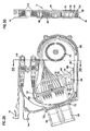
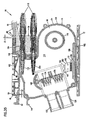
- FIG. 29 shows fiber optic splitter module 14 without a cover 96 exposing the interior features of fiber optic splitter module 14 including routing of a fiber optic cable within fiber optic splitter module 14.
- FIG. 30 illustrates a cross-sectional view taken along section line 30-30 of FIG 29 .
- a first cable 178 extends from connector 118 toward optical component 158, mounted within module housing 92.
- Optical component 158 may be a splitter or a fan-out or another type of optical component.
- optical component 158 is a fiber optic splitter that splits the signal of a single strand to a plurality of secondary signals.
- first cable 178 may be a multi-strand fiber cable with a plurality of strands of optical fiber and optical component may be a fanout to separate the individual strands into each of a plurality of second cables.
- First cable 178 as it extends toward optical component 158, is inserted through slits 172 (see FIGS. 22 , 29, and 30 ) located between optical component 158 and the inner side of first transverse sidewall 98 of module housing 94 and looped around first radius limiter 146 and then around second radius limiter 148 before being received by optical component 158.
- Second cables 180 extend from optical component 158 and are looped again all the way around first radius limiter 146 before heading toward crimp holders 174. From crimp holders 174, cables (not shown) crimped to the other ends of the crimps 176 exit the module through module exits 120.
- An outside cable may extend to rear end 70 of an adapter 64 of adapter assembly 16 and be terminated by a connector (not shown in FIG. 29 ) that is optically connected to connector 118 of module 14 through adapter 64 once module 14 is inserted within chassis 12. It should be noted that the routing of the fiber optic cables within module 14 as shown in FIGS. 29 and 30 is only one example and other ways of routing the cables within the module are possible.
- the embodiment of the fiber optic splitter module 14 shown in the FIGS. is configured such that it can accommodate reduced bend radius fiber.
- a reduced bend-radius fiber may have a bend radius of about 15 mm whereas a nonreduced bend-radius fiber may have a bend radius of about 30 mm.
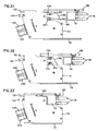
- FIGS. 31-35 The insertion of a splitter module 14 into chassis 12 is illustrated in FIGS. 31-35 .
- insertion of fiber optic module 12 into front opening 30 of chassis 12 begins the mating of module 14 to chassis 12 and to adapters 64 of adapter assembly 16.
- Top flanges engage 44 top slots 40 and bottom flanges 46 engages bottom slots 42 of chassis 12 as module 14 is inserted.
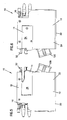
- chassis 12 includes a flexible shield 182 in each mounting location 38.
- Shield 182 is adapted to prevent protection against accidental exposure to light.
- Shield 182 is positioned in front end 68 of each adapter 64 of adapter assembly 16.
- shield 182 will prevent accidental exposure to these signals which might damage eyes or other sensitive organs, or nearby communications equipment. The insertion of splitter module 14 pushes shield 182 out of the way as illustrated in FIGS. 31-33 .
- Shield 182 is deflected by module 14 as module 14 is inserted through front opening 30 so that connectors 118 of module 14 can mate with adapters 64 of adapter assemblies 16.
- Shield 182 is preferably made of a resilient deformable material that will return to the position when module 14 is withdrawn from mounting location 38.
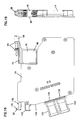
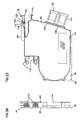
- a fiber optic splitter module 14 is shown partially inserted within chassis 12 prior to connectors 118 of splitter module 14 having contacted shield 182 of chassis 12.
- fiber optic splitter module 14 is shown in a position within chassis 12 with connectors 118 of fiber optic splitter module 14 making initial contact with shield 182 of chassis 12 to move shield 182 out of the way (a side cross-sectional view is shown in FIG. 34 ).
- fiber optic splitter module 14 is shown in a fully inserted position within chassis 12, having moved shield 182 out of the way (a side cross-sectional view is shown in FIG. 35 ).
- Shield 182 is configured such that shield 182 does not engage the ferrule 184 of connector 118 of splitter module 14 when connector 118 contacts shield 182 to move it out of the way. Instead, outer connector housing 150 pushes shield 182 out of the way.
- Shield 182 may be connected to chassis 12 by fasteners, or, alternatively, shield 182 may be formed integrally with chassis 12 or mounted by spot-welding or other fastening techniques.
- module 14 As shield 182 is fully deflected, further insertion of module 14 brings connectors 118 into contact with adapters 64 and connectors 118 are received within front ends 68 of adapters 64. Latch 52 is deflected inwardly as module 14 is inserted and then flexes back so that front lip 50 of bulkhead 48 is captured in recess 136. Module 14 is now in position to process and transmit signals from cable through first cable 178, optical component 158 and second cable 180 within module interior 114.
- recess 136 between the two tabs 132, 134 of latch 52 provides a certain amount of horizontal float for the splitter module 14 within chassis 12.
- Front lip 50 of bulkhead 48 is allowed to move a distance of D as indicated in FIG. 35 before it makes contact with square face 140 of rear tab 134.
- Splitter module 14 is configured such that, when splitter module 14 is pulled away from front 32 of chassis 12, distance D front lip 50 of bulkhead 48 travels before contacting square face 140 of rear tab 134 is less than the horizontal float (i.e., distance A) provided for adapter assembly 16, as discussed before.
- splitter module 14 provides a form of protection from accidentally disengaging connectors 118 of the module from adapter assemblies 16 at rear 28 of chassis 12.
- the size of recess 136 of module 14 is configured such that the horizontal float of splitter module 14 is interrupted before the adapter assembly 16 can be pulled far enough toward the front of chassis 12 to stop its horizontal movement and accidentally disengage connectors 118 of module 14 from adapters 64.
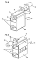
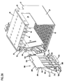
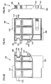
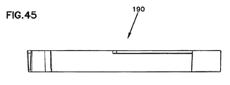
- FIGS. 36-45 illustrate a dust cap/test tool 190 configured for use with adapter assembly 16 of telecommunications assembly 10.
- Dust cap/test tool 190 includes a body 192 with a front end 194 and a rear end 196.
- Dust cap/test tool 190 includes a pair of connectors 118 protruding out from front end 194. As shown in FIG. 39 , the pair of connectors 118 are slidably inserted into connector holders 193 of the body 192 of dust cap/test tool 190.
- Connector holders 193 include slots 195 for receiving flanges of outer housings of connectors 118, as in housing 94 of splitter module 14.
- Dust cap/test tool 190 also includes a pair of dust plugs 198 protruding out from rear end 196.
- Dust cap/test tool 190 includes a top wall 200 and a bottom wall 202 and a first transverse side 204 and a second transverse side 206.
- the top and the bottom walls 200, 202 include top and bottom flanges 208, 210, respectively, for slidable insertion into chassis 12 similar to fiber optic splitter module 14.
- First transverse side 204 includes a radius limiter 212 for guiding cables terminated to connectors 118 of dust cap/test tool 190.
- dust cap/test tool 190 is slidably insertable within chassis 12 and usable in two different ways.
- dust cap/test tool 190 is shown being used as a test tool to test the optical signals input into the adapter assemblies 16. Since adapter assemblies 16 are located at rear end 28 of chassis 12 and front ends 68 of adapters 64 of adapter assemblies 16 are located in the interior of chassis 12 at rear 28, it becomes difficult to access to the connections for testing or other purposes.
- the pair of connectors 118 on front end 194 of dust cap/test tool 190 are designed to be coupled to adapters 64 of adapter assembly 16 when dust cap/test tool 190 is slidably inserted into chassis 12. In this manner, the connections at adapter assemblies 16 can be tested without having to uncouple adapter assemblies 16 from chassis 12 and without having to reach into chassis 12.
- dust cap/test tool 190 can also be flipped around 180° and used as a dust cap to seal the interior of adapters 64 from contaminants. If a splitter module 14 is not inserted within one of the mounting locations 38 of chassis 12, dust cap/test tool 190 can act as a placeholder and be slidably inserted within chassis 12.
- the dust plugs 198 include recessed portions 199 for receiving protruding tabs 89 of arms 91 of housing halves at the interior of an adapter 64. The recessed portions 199 help retain the dust plugs 198 within the adapters 64.
- dust cap/ test tool 190 is shown in combination with an adapter assembly 16 exploded off.
- dust cap/ test tool 190 is shown with an adapter assembly 16 mounted thereon and shown with one of the testing connectors 118 of dust cap/test tool 190 exploded off dust cap/test tool 190.
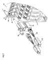
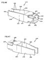
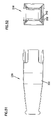
- FIGS. 46-52 illustrate a grip extension 218 adapted for use with connectors 118 coupled to rear 70 of adapters 64 of adapter assembly 16.
- Grip extension 218 is designed to add length to the outer housing 150 of a connector 118 to facilitate access to individual connectors 118 in dense environments such as the telecommunications assembly 10.
- Grip extension is preferably first mounted over a cable before the cable is terminated to a connector 118. Once the connector 118 is terminated to the cable, grip extension 218 is slid over the boot portion 220 of the connector and mounted to the outer housing 150 of connector 118 as shown in FIG. 7 .
- grip extension 218 includes an elongate body 222 with four cantilever arms extending from a front portion 224 of the body 222.
- Two of the opposing cantilever arms 226, 228 include protruding tabs 230 for engagement with the gripping surface 232 of outer housing 150 of connectors 118.
- Two of the other opposing cantilever arms 234, 236 include slits 238 for engaging the flanges 240 defined on connector outer housings 150.
- the rear portion 242 of the grip extension body 222 includes a top side 244, an open bottom side 246 and two transverse sides 248, 250 that taper in going in a direction from the front 224 to the back 242.
- Top and bottom sides 244, 246 include grip structures 252 to facilitate pulling on grip extensions 218 to remove connectors 118.
Landscapes
- Physics & Mathematics (AREA)
- General Physics & Mathematics (AREA)
- Optics & Photonics (AREA)
- Light Guides In General And Applications Therefor (AREA)
- Mechanical Coupling Of Light Guides (AREA)
Claims (25)
- Telekommunikationsanordnung (10), aufweisend:ein Chassis (12), welches eine Oberseite (18), einen Boden (20), eine Frontöffnung (30), eine rückseitige Öffnung (26) und erste und zweite Seitenteile (22, 24) einschließt, die sich zwischen der Frontöffnung und der rückseitigen Öffnung (30, 26) erstrecken, wobei das Chassis (12) eine Mehrzahl von Montageplätzen (38) definiert;ein Modul (14), welches eine Vorderwand (106) und eine Rückwand (104) definiert, wobei das Modul (14) so konfiguriert ist, dass es gleitbar in dem Chassis (12) durch die Frontöffnung (30) an einem der Montageplätze (38) aufgenommen ist, wobei das Modul (14) aus dem Chassis (12) durch die Frontöffnung (30) entnehmbar ist, das Modul (14) einen Faseroptik-Splitter (158) einschließt; undeine Adapteranordnung (16), die mindestens einen Faseroptik-Adapter (64) definiert, wobei die Adapteranordnung (16) so konfiguriert ist, dass sie gleitbar in dem Chassis (12) durch die rückseitige Öffnung (26) an einem der Montageplätze (38) aufgenommen ist, wobei die Adapteranordnung (16) aus dem Chassis (12) durch die rückseitige Öffnung (26) entnehmbar ist, der mindestens eine Faseroptik-Adapter (64) so konfiguriert ist, dass er einen ersten Faseroptik-Verbinder (118) mit einem zweiten Faseroptik-Verbinder (118) paart;wobei das Modul (114) mindestens einen ersten Faseroptik-Verbinder (118) einschließt, der aus der Rückwand (104) des Moduls (14) vorsteht, welcher dazu ausgebildet ist, in den mindestens einen Faseroptik-Adapter (64) der Adapteranordnung (16) eingesetzt zu werden, wenn das Modul (14) in das Chassis (12) eingesetzt wird, um sich mit dem zweiten Faseroptik-Verbinder (118) zu paaren;wobei ein erstes faseroptisches Signal, welches durch den zweiten Faseroptik-Verbinder (118) getragen wird, aus dem zweiten Faseroptik-Verbinder (118) zu dem mindestens einen ersten Faseroptik-Verbinder (118) geleitet wird und ein optisches Faserkabel (178), welches das erste faseroptische Signal trägt, sich von dem mindestens einen ersten Faseroptik-Verbinder (118) zu dem Faseroptik-Splitter (158) erstreckt und der Faseroptik-Splitter (158) das erste faseroptische Signal in eine Mehrzahl sekundärer faseroptischer Signale aufspaltet, die durch eine Verkabelung (180) getragen werden, die das Modul (14) durch die Vorderwand (106) des Moduls (14) verlässt.
- Telekommunikationsanordnung (10) nach Anspruch 1, wobei das Chassis (12) eine flexible Abschirmung (182) zum Abblocken von Licht von einem Vorderende (68) des Faseroptik-Adapters (64) der Adapteranordnung (16) einschließt, wobei die Abschirmung (182) zwischen einer Betriebsstellung und einer Nicht-Betriebsstellung bewegbar ist, die Abschirmung (182) so konfiguriert ist, dass sie sich von der Betriebsstellung in die Nicht-Betriebsstellung des Moduls (14) bewegt, wenn das Modul (14) gleitbar in das Chassis (12) eingesetzt wird.
- Telekommunikationsanordnung (10) nach Anspruch 2, wobei der mindestens eine Faseroptik-Verbinder (118) des Moduls (14) die Abschirmung (182) berührt, um sie aus der Betriebsstellung in die Nicht-Betriebsstellung zu bewegen, wenn das Modul (14) in das Chassis (12) eingesetzt wird.
- Telekommunikationsanordnung (10) nach Anspruch 1, wobei jeder Montageplatz (38) eine Front-Sperre (50) einschließt, die eine Schnappverbindung mit dem gleitbaren Modul (14) zum Halten des Moduls (14) im Chassis (12) bildet.
- Telekommunikationsanordnung (10) nach Anspruch 1, wobei das Modul (14) einen vorbestimmten Betrag an horizontalem Spiel in dem Chassis (12) hat, sobald es darin montiert ist, wobei das Modul (14) in der Lage ist, horizontal um eine vorbestimmte Strecke in dem Chassis (12) bewegt zu werden, wenn es darin montiert ist.
- Telekommunikationsanordnung (10) nach Anspruch 1, wobei jeder Montageplatz (38) eine Rückseite (54) mit einer Öffnung (56) zur Aufnahme eines Montagebefestigers (58) der Adapteranordnung (16) zum Halten der Adapteranordnung (16) im Chassis (12) einschließt.
- Telekommunikationsanordnung (10) nach Anspruch 6, wobei die Adapteranordnung (16) einen vorbestimmten Betrag an horizontalem Spiel relativ zum Chassis (12) einschließt, sobald sie darin montiert ist, wobei die Adapteranordnung (16) in der Lage ist, horizontal um eine vorbestimmte Strecke relativ zum Chassis (12) bewegt zu werden, wenn sie darin montiert ist.
- Telekommunikationsanordnung (10) nach Anspruch 1, wobei das Chassis (12) konfiguriert ist, um acht Module (14) und acht Adapteranordnungen (16) aufzunehmen.
- Telekommunikationsanordnung (10) nach Anspruch 1, wobei die Adapteranordnung (16) weiter aufweist:ein Gehäuse (66) welches eine Mehrzahl von integral gebildeten Faseroptik-Adaptern (64) definiert, wobei das Gehäuse eine Oberseite (74), einen Boden,eine erste und zweite Seitenwand, die sich zwischen der Oberseite (74) und dem Boden erstrecken, definiert, das Gehäuse (66) eine Montage-Gleitbahn (72) an der Oberseite (74) des Gehäuses (66) zum gleitbaren Führen der Adapteranordnung (16) in das Chassis (12) einschließt;wobei die Montage-Gleitbahn (72) einen horizontalen Führungsabschnitt (76) und einen vertikalen Führungsabschnitt (78) einschließt, wobei die Montage-Gleitbahn (72) einen Flansch (80) zum Halten eines Montage-Befestigers (58) einschließt, der Montage-Befestiger (58) sich in eine Richtung verlaufend von einer Front (68) des Gehäuses (66) zu einer Rückseite (70) des Gehäuses (66) erstreckt, der Montage-Befestiger (58) relativ zum Gehäuse (66) um eine Längsachse des Montage-Befestigers (58) drehbar ist und in eine sich zwischen der Front (68) und der Rückseite (70) des Gehäuses (66) erstreckende Richtung relativ zum Gehäuse (66) bewegbar ist;wobei jeder Adapter (64) des Gehäuses (66) eine Frontöffnung (68) zur Aufnahme eines ersten Faseroptik-Verbinders (118), eine rückseitige Öffnung (70) zur Aufnahme eines zweiten Faseroptik-Verbinders (118), der dazu ausgebildet ist, sich mit dem ersten Faseroptik-Verbinder (118) zu paaren, undeine Seitenöffnung (82) zur Aufnahme einer Zwingen-Ausrichtungshülse (86) und innere Gehäusehälften (88) hat; undwobei das Gehäuse (66) eine Tafel (90) einschließt, die die Seitenöffnung (82) der Faseroptik-Adapter (64) verschließt, um die Zwingen-Ausrichtungshülse (86) und die inneren Gehäusehälften (88) innerhalb des Faseroptik-Adapters (64) zu halten.
- Telekommunikationsanordnung (10) nach Anspruch 9, wobei der Montage-Befestiger (58) eine Flügelschraube ist.
- Telekommunikationsanordnung (10) nach Anspruch 9, wobei die Adapteranordnung (16) zwei integral gebildete Faseroptik-Adapter (64) einschließt.
- Verfahren zur Nutzung eines Telekommunikations-Chassis (12), welches aufweist:eine Oberseite (18), einen Boden (20), eine Frontöffnung (30), eine rückseitige Öffnung (26) und erste und zweite Seitenteile (22, 24), die sich zwischen der Frontöffnung und der Rückseitigen Öffnung (30, 26) erstrecken, wobei das Chassis (12) eine Mehrzahl von Montageplätzen (38) definiert, wobei das Verfahren die Schritte aufweist:(a) gleitendes Einsetzen einer Adapteranordnung (16), die mindestens einen Faseroptik-Adapter (64) definiert, in das Chassis (12) durch die rückseitige Öffnung (26) an einem der Montageplätze (38), wobei der mindestens eine Faseroptik-Adapter (64) so konfiguriert ist, dass er einen ersten Faseroptik-Verbinder (118) mit einem zweiten Faseroptik-Verbinder (118) paart; und(b) gleitendes Einsetzen eines Moduls (14), welches eine Vorderwand (106) und eine Rückwand (104) definiert und einen Faseroptik-Splitter 158 und mindestens einen Faseroptik-Verbinder (118) einschließt, der von der Rückwand (104) des Moduls (14) in das Chassis (12) vorsteht, durch die Frontöffnung (30) an einem der Montageplätze (38), um den mindestens einen Faseroptik-Verbinder (118) des Moduls (14) in einen Faseroptik-Adapter (64) der Adapteranordnung (16) an der Rückseite (26) des Chassis (12) einzusetzen, um ihn mit dem zweiten Faseroptik-Verbinder (118) zu paaren, wodurch ein erstes faseroptisches Signal, das durch den zweiten Faseroptik-Verbinder (118) getragen wird, vom zweiten Faseroptik-Verbinder (118) zu dem mindestens einen ersten Faseroptik-Verbinder (118) geleitet wird, und ein optisches Faserkabel (178), welches das erste faseroptische Signal trägt, sich von dem mindestens einen ersten Faseroptik-Verbinder (118) zu dem Faseroptik-Splitter (158) erstreckt, und der Faseroptik-Splitter (158) das erste faseroptische Signal in eine Mehrzahl sekundärer faseroptischer Signale aufspaltet, die durch die Verkabelung (180) getragen werden, die das Modul (14) durch die Vorderwand (106) des Moduls (14) verlässt.
- Telekommunikationsanordnung (10) nach Anspruch 1, weiter aufweisend eine Greif-Verlängerung (218) zur Nutzung mit einem Faseroptik-Verbinder (118), der so konfiguriert ist, dass er mit einem Faseroptik-Adapter (64) der Adapteranordnung (16) zu verbinden ist, wobei der Verbinder (118) ein Gehäuse (150) mit einer Ober- und Unterseite einschließt, dass vorstehende Wangen (240), eine erste und zweite Seitenwand, die Greif-Flächen (232) einschließen, eine Frontverbindungsseite und eine rückseitige Faseroptikkabel-Anschlussseite mit einer flexiblen Haube einschließt, wobei die Greif-Verlängerung (218) aufweist:einen langgestreckten Körper (222), der eine offene Vorderseite (224), ein offenes rückseitiges Ende (242), eine Oberseite (244), eine Unterseite (246) und erste und zweite Seitenwände (248, 250), die sich zwischen dem vorderen und hinteren Ende (224, 242) erstrecken, aufweist;wobei die erste und zweite Seitenwand (248, 250) zwei gegenüber liegende flexible Auslegerarme (226, 228) benachbart zur Vorderseite (224) definieren unddie Ober- und Unterseite (244, 246) zwei gegenüber liegende flexible Auslegerarme (234, 236) benachbart zur Vorderseite (224) definieren;wobei die durch die Seitenteile (248, 250) definierten Auslegerarme (226, 228) nach innen vorstehende Streifen (230) zum Eingreifen der Greifflächen (232) der Seitenflächen des Verbindergehäuses (150) einschließen, die durch die Ober- undUnterseite (244, 246) definierten beiden Auslegerarme (234, 236) Schlitze (238) zur Aufnahme der vorstehenden Wangen (240) der Ober- und Unterseite des Verbinderhäuses (150) einschließen; unddie Greif-Verlängerung (218) der Greifflächen (252) an dem hinteren Ende (242) einschließt, woduch die Greif-Verlängerung (218) so konfiguriert ist, dass sie mit dem Verbindergehäuse (150) mit einer Schnappverbindung verbunden werden kann, und wobei die Greif-Verlängerung (218) so konfiguriert ist, dass sie die flexible Haube des Verbinders (118) durch die offene Rückseite (242) aufnimmt.
- Telekommunikationsanordnung (10) nach Anspruch 13, wobei die Unterseite (246) der Greif-Verlängerung (218) einen offenen Abschnitt zur Aufnahme eines Abwärts-Biegens der Haube des Verbinders (118), wenn die Greif-Verlängerung (218) mit dem Verbindergehäuse (150) verbunden wird, einschließt.
- Telekommunikationsanordnung (10) nach Anspruch 13, wobei alle Auslegerarme (226, 228, 234, 236) der Greif-Verlängerung benachbart zur Vorderseite (224) ausbiegbar sind, um das Verbindergehäuse (150) aufzunehmen.
- Telekommunikationsanordnung (10) nach Anspruch 1, weiter aufweisend ein Kombinations-Staubschutz-/Testwerkzeug (190) wobei das Kombinations-Staubschutz-/Testwerkzeug (190) aufweist:einen Körper (192) mit einer Vorderseite (194), einer Rückseite (196), einer Oberseite (200), einer Unterseite (202) und einer ersten und zweiten Seitenwand (204, 205), wobei der Körper (192) eine Längsführungs-Wange (208) benachbart zur Oberseite (200) und eine Längsführungswange (210) benachbart zur Unterseite (202) definiert;wobei mindestens ein Faseroptik-Verbinder-Halter (193) benachbart der Vorderseite (194) vorgesehen ist;wobei mindestens ein Faseroptik-Staubstecker (198), der dazu ausgebildet ist, im Faseroptik-Adapter (64) aufgenommen zu werden, nahe der Rückseite (196) vorgesehen ist;wobei das Kombinations-Staubschutz-/Testwerkzeug (190) gleitend in das Telekommunikations-Chassis (12) in einer der beiden unterschiedlichen Orientierungen eingesetzt werden kann, wobei in einer ersten Orientierung die Vorderseite (194) zuerst in das Chassis (12) eingesetzt wird und wobei in einer zweiten Orientierung die Rückseite (196) zuerst in das Chassis (12) eingesetzt wird.
- Telekommunikationsanordnung (10) nach Anspruch 16, wobei der Körper (192) einen Fingergriff (214) benachbart zur Vorderseite (194) und einen Fingergriff (216) benachbart zur Rückseite (196) einschließt.
- Telekommunikationsanordnung (10) nach Anspruch 16, wobei der Körper (192) eine Kabelhandhabungsstruktur (212) definiert, die sich vom Verbinder-Halter (193) benachbart zur Vorderseite (194) zum Staubstecker (198) benachbart zur Rückseite (196) erstreckt.
- Telekommunikationsanordnung (10) nach Anspruch 16, wobei der Körper (192) im Wesentlichen rechteckig ist und der Verbinder-Halter (193) und der Staubstecker (198) in diagonal gegenüber liegenden Ecken des rechteckigen Körpers (192) positioniert sind.
- Telekommunikationsanordnung (10) nach Anspruch 16, wobei der Verbinder-Halter (193) zwei Faseroptik-Verbinder (118) aufnimmt und wobei das Staubschutz-/Testwerkzeug (190) zwei Staubstecker (198) einschließt.
- Telekommunikationsanordnung (10) nach Anspruch 16, wobei Verbinder (118) gleitbar in den Verbinder-Halter (193) des Körpers (192) einsetzbar und aus diesem entnehmbar sind.
- Telekommunikationsanordnung (10) nach Anspruch 16, wobei die Staubstecker (198) integral mit dem Körper (192) gebildet sind.
- Telekommunikationsanordnung (10) nach Anspruch 1, wobei das Modul (14) weiter aufweist:ein Gehäuse (92), welches einen Hauptgehäuseabschnitt (94) einschließt, der eine erste Seitenwand (98), die Vorderwand (106), die Rückwand (107), eine Deckfläche (100) und eine Bodenfläche (102) definiert, welche zusammen einen Innenraum (114) definieren; wobei das Hauptgehäuse (94) den mindestens einen ersten Faseroptik-Verbinder (118) einschließt, der sich von der Rückwand (104) zu einer Außenseite des Moduls (14) erstreckt;das Hauptgehäuse (94) mindestens einen Kabelausgang (120) einschließt, der sich von der Vorderwand (106) des Moduls (14) zur Außenseite des Moduls (14) erstreckt;wobei das Modul (14) den Faseroptik-Splitter (158) einschließt, welcher im Innenraum (114) des Moduls (14) benachbart zur Bodenfläche (102) des Hauptgehäuses (94) platziert ist;das Modul eine erste Kabelhandhabungsstruktur (148) einschließt, die im Inneren (114) des Moduls (14) dazu vorgesehen ist, Kabel (178) zu führen, die sich zwischen dem mindestens einen ersten Faseroptik-Verbinder (118) und dem Faseroptik-Splitter (158) erstrecken;das Modul (14) eine zweite Kabelhandhabungsstruktur (146) einschließt, die im Innenraum (114) des Moduls (14) vorgesehen ist, um Kabel (180) zu führen, die sich zwischen dem Faseroptik-Splitter (158) und dem Kabelausgang (120) erstrecken; unddas Gehäuse (92) des Moduls (14) einen Abdeckabschnitt (96) zum Befestigen des Hauptgehäuseabschnitts (94) zum Abschließen des Inneren (114) des Hauptgehäuseabschnitts (94) einschließt.
- Telekommunikationsanordnung (10) nach Anspruch 1, wobei das Modul (14) weiter aufweist:ein Gehäuse (92), welches einen Hauptgehäuseabschnitt (94) einschließt, der eine erste Seitenwand (98), die Vorderwand (106), die Rückwand (104), eine Deckfläche (100) und eine Bodenfläche (102) definiert, welche zusammen einen Innenraum (114) definieren;wobei das Hauptgehäuse (94) den mindestens einen ersten Faseroptik-Verbinder (118) einschließt, der sich von der Rückwand (104) zu einer Außenseite des Moduls (14) erstreckt;das Hauptgehäuse (94) mindestens einen Kabelausgang (120) einschließt, der sich von der Vorderwand (106) des Moduls (14) zur Außenseite des Moduls (14) erstreckt;wobei das Modul (14) den Faseroptik-Splitter (158) einschließt, welcher im Innenraum (114) des Moduls (14) benachbart zur Bodenfläche (102) des Hauptgehäuses (94) platziert ist;das Gehäuse (92) des Moduls (14) einen Abdeckabschnitt (96) zum Befestigen des Hauptgehäuseabschnitts (94) zum Abschließen des Inneren (114) des Hauptgehäuseabschnitts (94) einschließt; undwobei der Hauptgehäuseabschnitt (94) des Moduls (14) Crimp-Halter (174) einschließt, die benachbart den Kabelausgängen (120) angeordnet sind, zum Halten gecrimpter Enden (176) der Kabel (180), die vom Faseroptik-Splitter (158) zum Kabelausgang (120) verlaufen, wobei die Crimp-Halter (174) konfiguriert sind, um gleitbar gecrimpte Enden (176) der Kabel (180) in gestapelter Anordnung in eine Richtung aufzunehmen, die sich im Wesentlichen von der Abdeckung (96) zur ersten Seite (98) des hauptgehäuseabschnitts (94) erstreckt.
- Telekommunikationsanordnung (10) nach Anspruch 1, wobei das Modul (14) weiter aufweist:ein Gehäuse (92), welches einen Hauptgehäuseabschnitt (94) einschließt, der eine erste Seitenwand (98), die Vorderwand (106), die Rückwand (104), eine Deckfläche (100) und eine Bodenfläche (102) definiert, welche zusammen einen Innenraum (114) definieren; wobei das Hauptgehäuse (94) den mindestens einen ersten Faseroptik-Verbinder (118) einschließt, der sich von der Rückwand (104) zu einer Außenseite des Moduls (14) erstreckt;das Hauptgehäuse (94) mindestens einen Kabelausgang (120) einschließt, der sich von der Vorderwand (106) des Moduls (14) zur Außenseite des Moduls (14) erstreckt;wobei das Modul (14) den Faseroptik-Splitter (158) einschließt, welcher im Innenraum (114) des Moduls (14) benachbart zur Bodenfläche (102) des Hauptgehäuses (94) platziert ist;das Gehäuse (92) des Moduls (14) einen Abdeckabschnitt (96) zum Befestigen des Hauptgehäuseabschnitts (94) zum Abschließen des Inneren (114) des Hauptgehäuseabschnitts (94) einschließt; undwobei das Modul (14) einen flexiblen Auslegerarm (52) einschließt, der sich von der Vorderwand (106) des Hauptgehäuses (94) zur Außenseite des Moduls (14) erstreckt, um eine Schnappverbindung mit dem Chassis (12) bereitzustellen,wobei das Modul (14) auch einen feststehenden Griffstreifen (144) einschließt, der sich von der Vorderwand (106) des Hauptgehäuses (94) zur Außenseite des Moduls (14) benachbart dem flexiblen Auslegerarm (52) erstreckt.
Priority Applications (1)
| Application Number | Priority Date | Filing Date | Title |
|---|---|---|---|
| PL07749942T PL1987383T3 (pl) | 2006-02-13 | 2007-02-06 | Moduł rozdzielacza światłowodowego |
Applications Claiming Priority (2)
| Application Number | Priority Date | Filing Date | Title |
|---|---|---|---|
| US11/354,297 US7418181B2 (en) | 2006-02-13 | 2006-02-13 | Fiber optic splitter module |
| PCT/US2007/003035 WO2007094987A2 (en) | 2006-02-13 | 2007-02-06 | Fiber optic splitter module |
Publications (2)
| Publication Number | Publication Date |
|---|---|
| EP1987383A2 EP1987383A2 (de) | 2008-11-05 |
| EP1987383B1 true EP1987383B1 (de) | 2015-05-06 |
Family
ID=38042757
Family Applications (1)
| Application Number | Title | Priority Date | Filing Date |
|---|---|---|---|
| EP07749942.4A Not-in-force EP1987383B1 (de) | 2006-02-13 | 2007-02-06 | Glasfaser-splittermodul |
Country Status (13)
| Country | Link |
|---|---|
| US (11) | US7418181B2 (de) |
| EP (1) | EP1987383B1 (de) |
| JP (1) | JP5209503B2 (de) |
| KR (1) | KR101459158B1 (de) |
| CN (2) | CN102087392B (de) |
| AR (1) | AR059572A1 (de) |
| AU (1) | AU2007215468B2 (de) |
| BR (1) | BRPI0707734A8 (de) |
| DK (1) | DK1987383T3 (de) |
| ES (1) | ES2539428T3 (de) |
| PL (1) | PL1987383T3 (de) |
| TW (1) | TWI429973B (de) |
| WO (1) | WO2007094987A2 (de) |
Cited By (1)
| Publication number | Priority date | Publication date | Assignee | Title |
|---|---|---|---|---|
| EP3435130B1 (de) * | 2014-04-03 | 2021-10-20 | CommScope Connectivity Belgium BVBA | Splittermodul und gehäuse dafür |
Families Citing this family (198)
| Publication number | Priority date | Publication date | Assignee | Title |
|---|---|---|---|---|
| US6885798B2 (en) | 2003-09-08 | 2005-04-26 | Adc Telecommunications, Inc. | Fiber optic cable and furcation module |
| GB0402187D0 (en) | 2004-01-31 | 2004-03-03 | Tyco Electronics Raychem Nv | A crimp for an optical cable connector |
| US7400813B2 (en) | 2005-05-25 | 2008-07-15 | Adc Telecommunications, Inc. | Fiber optic splitter module |
| EP1910882A1 (de) | 2005-07-15 | 2008-04-16 | Auburn University | Mikroskop-beleuchtungseinrichtung undadapter für dunkel- und hellfeldbeleuchtung |
| US7623749B2 (en) | 2005-08-30 | 2009-11-24 | Adc Telecommunications, Inc. | Fiber distribution hub with modular termination blocks |
| JP3987078B2 (ja) * | 2005-08-31 | 2007-10-03 | 日本電信電話株式会社 | 光コネクタ |
| US7245809B1 (en) * | 2005-12-28 | 2007-07-17 | Adc Telecommunications, Inc. | Splitter modules for fiber distribution hubs |
| US7816602B2 (en) | 2006-02-13 | 2010-10-19 | Adc Telecommunications, Inc. | Fiber distribution hub with outside accessible grounding terminals |
| US7418181B2 (en) | 2006-02-13 | 2008-08-26 | Adc Telecommunications, Inc. | Fiber optic splitter module |
| US7711234B2 (en) * | 2006-10-02 | 2010-05-04 | Adc Telecommunications, Inc. | Reskinnable fiber distribution hub |
| US7689089B2 (en) | 2006-10-11 | 2010-03-30 | Panduit Corp. | Release latch for pre-terminated cassette |
| US7349616B1 (en) | 2007-01-12 | 2008-03-25 | Corning Cable Systems Llc | Fiber optic local convergence points for multiple dwelling units |
| US7493002B2 (en) | 2007-01-19 | 2009-02-17 | Adc Telecommunications, Inc. | Fiber optic adapter cassette and panel |
| US7522805B2 (en) * | 2007-03-09 | 2009-04-21 | Adc Telecommunications, Inc. | Wall mount distribution arrangement |
| JP4343238B2 (ja) * | 2007-05-29 | 2009-10-14 | 日本航空電子工業株式会社 | 組立体 |
| US7734138B2 (en) * | 2007-05-30 | 2010-06-08 | Corning Cable Systems Llc | Fiber optic connector holders |
| US7590328B2 (en) | 2007-08-02 | 2009-09-15 | Adc Telecommunications, Inc. | Fiber termination block with splitters |
| US7720344B2 (en) * | 2007-10-22 | 2010-05-18 | Adc Telecommunications, Inc. | Fiber distribution hub |
| US7885505B2 (en) * | 2007-10-22 | 2011-02-08 | Adc Telecommunications, Inc. | Wavelength division multiplexing module |
| US7536075B2 (en) * | 2007-10-22 | 2009-05-19 | Adc Telecommunications, Inc. | Wavelength division multiplexing module |
| US7751672B2 (en) * | 2007-10-31 | 2010-07-06 | Adc Telecommunications, Inc. | Low profile fiber distribution hub |
| US8229265B2 (en) | 2007-11-21 | 2012-07-24 | Adc Telecommunications, Inc. | Fiber distribution hub with multiple configurations |
| US8238709B2 (en) | 2007-12-18 | 2012-08-07 | Adc Telecommunications, Inc. | Multi-configuration mounting system for fiber distribution hub |
| US8107816B2 (en) | 2008-01-29 | 2012-01-31 | Adc Telecommunications, Inc. | Wavelength division multiplexing module |
| US7715682B2 (en) * | 2008-03-04 | 2010-05-11 | Adc Telecommunications, Inc. | Fiber distribution hub having an adjustable plate |
| US8270796B2 (en) * | 2008-03-04 | 2012-09-18 | Adc Telecommunications, Inc. | Multi-port adapter block |
| US8452148B2 (en) | 2008-08-29 | 2013-05-28 | Corning Cable Systems Llc | Independently translatable modules and fiber optic equipment trays in fiber optic equipment |
| US11294136B2 (en) | 2008-08-29 | 2022-04-05 | Corning Optical Communications LLC | High density and bandwidth fiber optic apparatuses and related equipment and methods |
| US8184938B2 (en) | 2008-08-29 | 2012-05-22 | Corning Cable Systems Llc | Rear-installable fiber optic modules and equipment |
| AU2015203580A1 (en) * | 2008-08-29 | 2015-07-23 | Corning Optical Communications LLC | Rear-installable fiber optic modules and equipment |
| US8573855B2 (en) * | 2008-10-06 | 2013-11-05 | Adc Telecommunications, Inc. | Fanout cable assembly and method |
| MX2011005380A (es) * | 2008-11-21 | 2011-06-06 | Adc Telecommunications Inc | Modulo de telecomunicaciones de fibra optica. |
| US8428418B2 (en) * | 2008-12-09 | 2013-04-23 | Adc Telecommunications, Inc. | Fiber optic adapter plate and cassette |
| WO2010083369A1 (en) | 2009-01-15 | 2010-07-22 | Adc Telecommunications, Inc. | Fiber optic module, chassis and adapter |
| ATE534049T1 (de) | 2009-02-24 | 2011-12-15 | Ccs Technology Inc | Haltevorrichtung für ein kabel oder eine anordnung zur verwendung mit einem kabel |
| EP4152649A1 (de) | 2009-03-05 | 2023-03-22 | Commscope Technologies LLC | Verfahren, systeme und vorrichtung zur integration von drahtloser technologie in ein glasfasernetz |
| US8699838B2 (en) | 2009-05-14 | 2014-04-15 | Ccs Technology, Inc. | Fiber optic furcation module |
| TWI471621B (zh) * | 2009-05-20 | 2015-02-01 | Sumitomo Electric Industries | Splitter module |
| US8538226B2 (en) | 2009-05-21 | 2013-09-17 | Corning Cable Systems Llc | Fiber optic equipment guides and rails configured with stopping position(s), and related equipment and methods |
| US9075216B2 (en) | 2009-05-21 | 2015-07-07 | Corning Cable Systems Llc | Fiber optic housings configured to accommodate fiber optic modules/cassettes and fiber optic panels, and related components and methods |
| US8244089B2 (en) * | 2009-06-03 | 2012-08-14 | Emerson Network Power, Energy Systems, North America, Inc. | Dust caps for fiber optic connectors |
| US7899300B2 (en) * | 2009-06-03 | 2011-03-01 | Emerson Network Power, Energy Systems, North America, Inc. | Dust caps for fiber optic connectors |
| WO2010148336A1 (en) | 2009-06-19 | 2010-12-23 | Corning Cable Systems Llc | High density and bandwidth fiber optic apparatuses and related equipment and methods |
| US8712206B2 (en) | 2009-06-19 | 2014-04-29 | Corning Cable Systems Llc | High-density fiber optic modules and module housings and related equipment |
| CA2765830A1 (en) | 2009-06-19 | 2010-12-23 | Corning Cable Systems Llc | High fiber optic cable packing density apparatus |
| EP2446312A1 (de) * | 2009-06-22 | 2012-05-02 | Corning Cable Systems LLC | Positionierungsvorrichtung für glasfaserkabel |
| ES2403007A1 (es) * | 2009-07-01 | 2013-05-13 | Adc Telecommunications, Inc | Concentrador de distribución de fibra para montaje en pared. |
| US8346047B2 (en) * | 2009-08-13 | 2013-01-01 | Commscope, Inc. Of North Carolina | Fiber management component |
| WO2011029022A2 (en) * | 2009-09-04 | 2011-03-10 | Adc Telecommunications, Inc. | Pedestal terminal with swing frame |
| US8714368B2 (en) * | 2009-09-09 | 2014-05-06 | Adc Telecommunications, Inc. | Pass-through trough |
| US8428419B2 (en) * | 2009-09-23 | 2013-04-23 | Adc Telecommunications, Inc. | Fiber distribution hub with internal cable spool |
| WO2011066364A2 (en) * | 2009-11-25 | 2011-06-03 | Adc Telecommunications, Inc. | Methods, systems and devices for providing fiber-to-the-desktop |
| US20110129185A1 (en) * | 2009-11-30 | 2011-06-02 | Lewallen C Paul | Articulated Strain Relief Boot on a Fiber Optic Module and Associated Methods |
| US8625950B2 (en) | 2009-12-18 | 2014-01-07 | Corning Cable Systems Llc | Rotary locking apparatus for fiber optic equipment trays and related methods |
| US8498510B2 (en) * | 2010-01-18 | 2013-07-30 | Adc Telecommunications, Inc. | Fiber distribution enclosure |
| US8824850B2 (en) * | 2010-01-26 | 2014-09-02 | Adc Telecommunications, Inc. | Insect-infestation prevention device for a telecommunications equipment housing |
| US8593828B2 (en) * | 2010-02-04 | 2013-11-26 | Corning Cable Systems Llc | Communications equipment housings, assemblies, and related alignment features and methods |
| US8958679B2 (en) | 2010-03-02 | 2015-02-17 | Tyco Electronics Services Gmbh | Fibre-optic telecommunications module |
| US8649649B2 (en) | 2010-03-03 | 2014-02-11 | Adc Telecommunications, Inc. | Fiber distribution hub with connectorized stub cables |
| US20110235986A1 (en) * | 2010-03-24 | 2011-09-29 | Adc Telecommunications, Inc. | Optical fiber drawer with connectorized stub cable |
| US8913866B2 (en) | 2010-03-26 | 2014-12-16 | Corning Cable Systems Llc | Movable adapter panel |
| US8837940B2 (en) | 2010-04-14 | 2014-09-16 | Adc Telecommunications, Inc. | Methods and systems for distributing fiber optic telecommunication services to local areas and for supporting distributed antenna systems |
| US9078287B2 (en) | 2010-04-14 | 2015-07-07 | Adc Telecommunications, Inc. | Fiber to the antenna |
| AU2011265751B2 (en) | 2010-04-16 | 2015-09-10 | Corning Optical Communications LLC | Sealing and strain relief device for data cables |
| EP2381284B1 (de) | 2010-04-23 | 2014-12-31 | CCS Technology Inc. | Glasfaserverteilungsvorrichtung für Unterboden |
| US9239442B2 (en) | 2010-04-27 | 2016-01-19 | Adc Communications (Shanghai) Co., Ltd. | Fiber optic module and chassis |
| US8879881B2 (en) | 2010-04-30 | 2014-11-04 | Corning Cable Systems Llc | Rotatable routing guide and assembly |
| US8705926B2 (en) | 2010-04-30 | 2014-04-22 | Corning Optical Communications LLC | Fiber optic housings having a removable top, and related components and methods |
| US9720195B2 (en) | 2010-04-30 | 2017-08-01 | Corning Optical Communications LLC | Apparatuses and related components and methods for attachment and release of fiber optic housings to and from an equipment rack |
| US9519118B2 (en) | 2010-04-30 | 2016-12-13 | Corning Optical Communications LLC | Removable fiber management sections for fiber optic housings, and related components and methods |
| US8660397B2 (en) | 2010-04-30 | 2014-02-25 | Corning Cable Systems Llc | Multi-layer module |
| US9075217B2 (en) | 2010-04-30 | 2015-07-07 | Corning Cable Systems Llc | Apparatuses and related components and methods for expanding capacity of fiber optic housings |
| US9632270B2 (en) | 2010-04-30 | 2017-04-25 | Corning Optical Communications LLC | Fiber optic housings configured for tool-less assembly, and related components and methods |
| US8705930B2 (en) | 2010-06-25 | 2014-04-22 | Adc Telecommunications, Inc. | Transition housing and cap for fiber breakout assembly |
| US8718436B2 (en) | 2010-08-30 | 2014-05-06 | Corning Cable Systems Llc | Methods, apparatuses for providing secure fiber optic connections |
| EP2437090A1 (de) * | 2010-10-04 | 2012-04-04 | Tyco Electronics Raychem BVBA | Kabelanschlussfach, Fachvorrichtung, Fachhalter und Verfahren zum Anschließen eines Steckverbinders an einen Gegenstecker |
| US9279951B2 (en) | 2010-10-27 | 2016-03-08 | Corning Cable Systems Llc | Fiber optic module for limited space applications having a partially sealed module sub-assembly |
| GB2493857B (en) | 2010-10-28 | 2013-12-25 | Aj World Co Ltd | Field assembled optical connector |
| KR101105664B1 (ko) * | 2010-10-28 | 2012-01-18 | 주식회사 에이제이월드 | 현장 조립형 광커넥터 |
| US8662760B2 (en) | 2010-10-29 | 2014-03-04 | Corning Cable Systems Llc | Fiber optic connector employing optical fiber guide member |
| US9116324B2 (en) | 2010-10-29 | 2015-08-25 | Corning Cable Systems Llc | Stacked fiber optic modules and fiber optic equipment configured to support stacked fiber optic modules |
| CA2819235C (en) | 2010-11-30 | 2018-01-16 | Corning Cable Systems Llc | Fiber device holder and strain relief device |
| KR101114289B1 (ko) * | 2010-12-06 | 2012-03-05 | 주식회사 에이제이월드 | 현장 조립형 광커넥터 |
| WO2012106510A2 (en) | 2011-02-02 | 2012-08-09 | Corning Cable Systems Llc | Dense fiber optic connector assemblies and related connectors and cables suitable for establishing optical connections for optical backplanes in equipment racks |
| WO2013105998A2 (en) * | 2011-02-16 | 2013-07-18 | Tyco Electronics Corporation | Fiber optic closure |
| US9606303B2 (en) * | 2011-03-01 | 2017-03-28 | Us Conec, Ltd. | Grouping device for high density connector arrangements |
| US9182563B2 (en) | 2011-03-31 | 2015-11-10 | Adc Telecommunications, Inc. | Adapter plate for fiber optic module |
| US20120263479A1 (en) * | 2011-04-18 | 2012-10-18 | Neophotonics Corporation | Optical network communication system with variable optical attenuation and method of operation thereof |
| US9008485B2 (en) | 2011-05-09 | 2015-04-14 | Corning Cable Systems Llc | Attachment mechanisms employed to attach a rear housing section to a fiber optic housing, and related assemblies and methods |
| WO2013003303A1 (en) | 2011-06-30 | 2013-01-03 | Corning Cable Systems Llc | Fiber optic equipment assemblies employing non-u-width-sized housings and related methods |
| EP2544035A1 (de) * | 2011-07-07 | 2013-01-09 | 3M Innovative Properties Company | Glasfaserverteilungsvorrichtung |
| US8953924B2 (en) | 2011-09-02 | 2015-02-10 | Corning Cable Systems Llc | Removable strain relief brackets for securing fiber optic cables and/or optical fibers to fiber optic equipment, and related assemblies and methods |
| US9417401B2 (en) | 2011-09-06 | 2016-08-16 | Commscope Technologies Llc | Adapter for fiber optic module |
| US9417418B2 (en) | 2011-09-12 | 2016-08-16 | Commscope Technologies Llc | Flexible lensed optical interconnect device for signal distribution |
| CN103917904A (zh) | 2011-10-07 | 2014-07-09 | Adc电信公司 | 光纤盒、系统和方法 |
| US9038832B2 (en) | 2011-11-30 | 2015-05-26 | Corning Cable Systems Llc | Adapter panel support assembly |
| EP2795811B1 (de) | 2011-12-22 | 2018-08-22 | CommScope Technologies LLC | Faseroptische wandplatte mit redundanzsystem |
| US20130308916A1 (en) * | 2012-05-16 | 2013-11-21 | Scott Eaker Buff | High-density port tap fiber optic modules, and related systems and methods for monitoring optical networks |
| US9250409B2 (en) | 2012-07-02 | 2016-02-02 | Corning Cable Systems Llc | Fiber-optic-module trays and drawers for fiber-optic equipment |
| US9042702B2 (en) | 2012-09-18 | 2015-05-26 | Corning Cable Systems Llc | Platforms and systems for fiber optic cable attachment |
| US9146374B2 (en) | 2012-09-28 | 2015-09-29 | Adc Telecommunications, Inc. | Rapid deployment packaging for optical fiber |
| ES2792122T3 (es) | 2012-09-28 | 2020-11-10 | Commscope Connectivity Uk Ltd | Casete de fibra óptica |
| US9223094B2 (en) | 2012-10-05 | 2015-12-29 | Tyco Electronics Nederland Bv | Flexible optical circuit, cassettes, and methods |
| ES2551077T3 (es) | 2012-10-26 | 2015-11-16 | Ccs Technology, Inc. | Unidad de gestión de fibra óptica y dispositivo de distribución de fibra óptica |
| WO2014079478A1 (en) | 2012-11-20 | 2014-05-30 | Light In Light Srl | High speed laser processing of transparent materials |
| US10031305B2 (en) | 2012-12-19 | 2018-07-24 | CommScope Connectivity Belgium BVBA | Distribution device with incrementally added splitters |
| EP2754524B1 (de) | 2013-01-15 | 2015-11-25 | Corning Laser Technologies GmbH | Verfahren und Vorrichtung zum laserbasierten Bearbeiten von flächigen Substraten, d.h. Wafer oder Glaselement, unter Verwendung einer Laserstrahlbrennlinie |
| US8985862B2 (en) | 2013-02-28 | 2015-03-24 | Corning Cable Systems Llc | High-density multi-fiber adapter housings |
| US9728945B2 (en) | 2013-03-13 | 2017-08-08 | Go!Foton Holdings, Inc. | Patch panel assembly |
| US9274300B2 (en) | 2013-04-22 | 2016-03-01 | M2 Optics, Inc. | High density enclosure for optical modules |
| US9435975B2 (en) | 2013-03-15 | 2016-09-06 | Commscope Technologies Llc | Modular high density telecommunications frame and chassis system |
| EP2781296B1 (de) | 2013-03-21 | 2020-10-21 | Corning Laser Technologies GmbH | Vorrichtung und verfahren zum ausschneiden von konturen aus flächigen substraten mittels laser |
| US9584879B2 (en) | 2013-05-29 | 2017-02-28 | Go!Foton Holdings, Inc. | Patch panel cable retention mechanisms |
| US9462356B2 (en) * | 2013-05-29 | 2016-10-04 | Go!Foton Holdings, Inc. | Patch panel assembly |
| US9581781B2 (en) | 2013-06-24 | 2017-02-28 | Go!Foton Holdings, Inc. | Patch panel pivoting tray cable retention mechanisms |
| US9301030B2 (en) | 2013-11-11 | 2016-03-29 | Commscope Technologies Llc | Telecommunications module |
| US11556039B2 (en) | 2013-12-17 | 2023-01-17 | Corning Incorporated | Electrochromic coated glass articles and methods for laser processing the same |
| US9676167B2 (en) | 2013-12-17 | 2017-06-13 | Corning Incorporated | Laser processing of sapphire substrate and related applications |
| US10293436B2 (en) | 2013-12-17 | 2019-05-21 | Corning Incorporated | Method for rapid laser drilling of holes in glass and products made therefrom |
| US9850160B2 (en) | 2013-12-17 | 2017-12-26 | Corning Incorporated | Laser cutting of display glass compositions |
| US20150165560A1 (en) | 2013-12-17 | 2015-06-18 | Corning Incorporated | Laser processing of slots and holes |
| US9815730B2 (en) | 2013-12-17 | 2017-11-14 | Corning Incorporated | Processing 3D shaped transparent brittle substrate |
| US10442719B2 (en) | 2013-12-17 | 2019-10-15 | Corning Incorporated | Edge chamfering methods |
| US9701563B2 (en) | 2013-12-17 | 2017-07-11 | Corning Incorporated | Laser cut composite glass article and method of cutting |
| EP3100090A4 (de) | 2014-01-28 | 2017-09-06 | ADC Telecommunications Inc. | Verschiebbares glasfaser-verbindungsmodul mit kabelüberlängenverwaltung |
| US9494758B2 (en) | 2014-04-03 | 2016-11-15 | Commscope Technologies Llc | Fiber optic distribution system |
| CN106687841B (zh) | 2014-06-17 | 2020-08-14 | 康普连通比利时私人有限公司 | 线缆配线系统 |
| WO2015200321A1 (en) | 2014-06-23 | 2015-12-30 | Adc Telecommunications, Inc. | Fiber cable fan-out assembly and method |
| SG11201610605PA (en) | 2014-06-23 | 2017-01-27 | Adc Telecommunications Inc | Bladed chassis systems |
| TWI730945B (zh) | 2014-07-08 | 2021-06-21 | 美商康寧公司 | 用於雷射處理材料的方法與設備 |
| KR20170028943A (ko) * | 2014-07-14 | 2017-03-14 | 코닝 인코포레이티드 | 조정가능한 레이저 빔 촛점 라인을 사용하여 투명한 재료를 처리하는 방법 및 시스템 |
| EP3169479B1 (de) | 2014-07-14 | 2019-10-02 | Corning Incorporated | Verfahren und system zum stoppen von inzidenter rissausbreitung in einem transparenten material |
| CN107073641B (zh) | 2014-07-14 | 2020-11-10 | 康宁股份有限公司 | 接口块;用于使用这种接口块切割在波长范围内透明的衬底的系统和方法 |
| WO2016010949A1 (en) | 2014-07-14 | 2016-01-21 | Corning Incorporated | Method and system for forming perforations |
| WO2016012295A1 (en) | 2014-07-22 | 2016-01-28 | Tyco Electronics Raychem Bvba | Door hinge mechanism for telecommunicatons panel |
| FR3025613B1 (fr) * | 2014-09-04 | 2016-11-25 | Acome Soc Coop Et Participative Soc Anonyme Coop De Production A Capital Variable | Dispositif de terminaison interieure optique et ensemble associe |
| CN106715813B (zh) | 2014-09-11 | 2018-12-11 | Adc电信股份有限公司 | 用于远程通信面板的门铰链机构 |
| EP3205034A4 (de) | 2014-10-06 | 2018-06-27 | ADC Telecommunications Inc. | Ermöglichung der montage von glasfasernetzen |
| US10054753B2 (en) | 2014-10-27 | 2018-08-21 | Commscope Technologies Llc | Fiber optic cable with flexible conduit |
| US10047001B2 (en) | 2014-12-04 | 2018-08-14 | Corning Incorporated | Glass cutting systems and methods using non-diffracting laser beams |
| CN107406293A (zh) | 2015-01-12 | 2017-11-28 | 康宁股份有限公司 | 使用多光子吸收方法来对经热回火的基板进行激光切割 |
| US11773004B2 (en) | 2015-03-24 | 2023-10-03 | Corning Incorporated | Laser cutting and processing of display glass compositions |
| KR20170131638A (ko) | 2015-03-27 | 2017-11-29 | 코닝 인코포레이티드 | 가스 투과성 유리창 및 이의 제작방법 |
| EP3822676A1 (de) | 2015-04-02 | 2021-05-19 | CommScope Technologies LLC | Glasfasernetzwerkarchitektur mit glasfasersteckern mit hoher faserzahl |
| WO2016170171A2 (en) * | 2015-04-22 | 2016-10-27 | CommScope Connectivity Belgium BVBA | Cable storage arrangement |
| WO2017011296A1 (en) | 2015-07-10 | 2017-01-19 | Corning Incorporated | Methods of continuous fabrication of holes in flexible substrate sheets and products relating to the same |
| CN104977663B (zh) * | 2015-07-24 | 2017-05-31 | 浙江盈峰光通信科技有限公司 | 光纤连接器和适配器的防误插、防尘结构 |
| EP3329346A4 (de) | 2015-07-29 | 2019-06-12 | Commscope Technologies LLC | Beschaufelte chassissysteme |
| AU2015207954C1 (en) | 2015-07-31 | 2022-05-05 | Adc Communications (Australia) Pty Limited | Cable breakout assembly |
| EP3338125A4 (de) | 2015-08-21 | 2019-04-17 | Commscope Technologies LLC | Telekommunikationsmodul |
| WO2017046190A2 (en) | 2015-09-14 | 2017-03-23 | CommScope Connectivity Belgium BVBA | Terminal enclosure with modular aspects and modules for interfacing with the terminal enclosure |
| US10606009B2 (en) | 2015-12-01 | 2020-03-31 | CommScope Connectivity Belgium BVBA | Cable distribution system with fan out devices |
| WO2017129815A1 (en) | 2016-01-28 | 2017-08-03 | CommScope Connectivity Belgium BVBA | Modular hybrid closure |
| CN108780200B (zh) | 2016-03-18 | 2021-05-07 | 康普技术有限责任公司 | 光纤电缆扇出管道结构、部件和方法 |
| US10222571B2 (en) | 2016-04-07 | 2019-03-05 | Commscope Technologies Llc | Telecommunications module and frame |
| ES2851948T3 (es) | 2016-04-19 | 2021-09-09 | Commscope Inc North Carolina | Bastidor de telecomunicaciones con bandejas deslizables |
| US11674345B2 (en) | 2016-04-19 | 2023-06-13 | Commscope, Inc. Of North Carolina | Door assembly for a telecommunications chassis with a combination hinge structure |
| US10295771B2 (en) | 2016-05-03 | 2019-05-21 | Corning Optical Communications LLC | Telecommunications terminal with removable modules |
| JP6938543B2 (ja) | 2016-05-06 | 2021-09-22 | コーニング インコーポレイテッド | 透明基板からの、輪郭設定された形状のレーザ切断及び取り外し |
| US10410883B2 (en) | 2016-06-01 | 2019-09-10 | Corning Incorporated | Articles and methods of forming vias in substrates |
| US10794679B2 (en) | 2016-06-29 | 2020-10-06 | Corning Incorporated | Method and system for measuring geometric parameters of through holes |
| CN105929512A (zh) * | 2016-07-11 | 2016-09-07 | 上海博中机电科技有限公司 | 一种分支模块型预制光缆 |
| KR20190035805A (ko) | 2016-07-29 | 2019-04-03 | 코닝 인코포레이티드 | 레이저 처리를 위한 장치 및 방법 |
| KR102423775B1 (ko) | 2016-08-30 | 2022-07-22 | 코닝 인코포레이티드 | 투명 재료의 레이저 가공 |
| US10890730B2 (en) | 2016-08-31 | 2021-01-12 | Commscope Technologies Llc | Fiber optic cable clamp and clamp assembly |
| US10730783B2 (en) | 2016-09-30 | 2020-08-04 | Corning Incorporated | Apparatuses and methods for laser processing transparent workpieces using non-axisymmetric beam spots |
| US10914909B2 (en) | 2016-10-13 | 2021-02-09 | Commscope Technologies Llc | Fiber optic breakout transition assembly incorporating epoxy plug and cable strain relief |
| KR102428350B1 (ko) | 2016-10-24 | 2022-08-02 | 코닝 인코포레이티드 | 시트형 유리 기판의 레이저 기반 기계 가공을 위한 기판 프로세싱 스테이션 |
| US10752534B2 (en) | 2016-11-01 | 2020-08-25 | Corning Incorporated | Apparatuses and methods for laser processing laminate workpiece stacks |
| USD825475S1 (en) | 2017-01-16 | 2018-08-14 | Corning Research & Development Corporation | Fiber optic splitter module with surface ornamentation |
| WO2018141844A2 (en) | 2017-02-01 | 2018-08-09 | CommScope Connectivity Belgium BVBA | Sealed connection terminal |
| US10688599B2 (en) | 2017-02-09 | 2020-06-23 | Corning Incorporated | Apparatus and methods for laser processing transparent workpieces using phase shifted focal lines |
| US10291969B2 (en) | 2017-02-14 | 2019-05-14 | Go!Foton Holdings, Inc. | Rear cable management |
| CA3056998C (en) * | 2017-03-21 | 2020-11-10 | Xenoptics Ip Holdings Pty Ltd. | Optical fiber interconnect management |
| US10656361B2 (en) | 2017-05-04 | 2020-05-19 | Go!Foton Holdings, Inc. | Cable termination assembly |
| EP3622336A4 (de) | 2017-05-08 | 2021-01-20 | Commscope Technologies LLC | Glasfaser-breakout-übergangsanordnung |
| US10580725B2 (en) | 2017-05-25 | 2020-03-03 | Corning Incorporated | Articles having vias with geometry attributes and methods for fabricating the same |
| US11078112B2 (en) | 2017-05-25 | 2021-08-03 | Corning Incorporated | Silica-containing substrates with vias having an axially variable sidewall taper and methods for forming the same |
| US10626040B2 (en) | 2017-06-15 | 2020-04-21 | Corning Incorporated | Articles capable of individual singulation |
| EP3646092B1 (de) * | 2017-06-28 | 2021-11-24 | Corning Research & Development Corporation | Kompakte glasfaserverbinder |
| EP3692404A4 (de) | 2017-10-02 | 2021-06-16 | Commscope Technologies LLC | Faseroptische schaltung und herstellungsverfahren |
| EP3695258B1 (de) * | 2017-10-09 | 2023-12-06 | CommScope Connectivity Belgium BVBA | Kabelfixiervorrichtungen und -verfahren |
| US10401586B2 (en) | 2017-10-30 | 2019-09-03 | Corning Research & Development Corporation | Telecommunications modules having multiple body sections and forward facing input and output adapters |
| US12180108B2 (en) | 2017-12-19 | 2024-12-31 | Corning Incorporated | Methods for etching vias in glass-based articles employing positive charge organic molecules |
| US11554984B2 (en) | 2018-02-22 | 2023-01-17 | Corning Incorporated | Alkali-free borosilicate glasses with low post-HF etch roughness |
| US11169344B2 (en) * | 2018-02-27 | 2021-11-09 | Commscope Technologies Llc | Common module storage within a fiber distribution hub |
| US10264701B1 (en) * | 2018-06-28 | 2019-04-16 | Hewlett Packard Enterprise Development Lp | Multi-configuration resource module bay |
| WO2020091823A1 (en) * | 2018-11-02 | 2020-05-07 | Go!Foton Holdings, Inc. | Cable termination assembly with disengagement prevention structures |
| US11531170B2 (en) | 2018-11-28 | 2022-12-20 | Go!Foton Holdings, Inc. | Intelligent patch panel |
| US10585256B1 (en) | 2019-03-29 | 2020-03-10 | Corning Research & Development Corporation | Terminal of an optical fiber network having a bypass module |
| US11166392B2 (en) * | 2019-10-21 | 2021-11-02 | Ciena Corporation | Spring-type latch for securing a networking module within a slot of a chassis |
| WO2021148544A1 (en) * | 2020-01-22 | 2021-07-29 | CommScope Connectivity Belgium BVBA | Cable termination units for optical fiber distribution elements |
| CN115210621B (zh) * | 2020-03-05 | 2024-07-02 | 住友电气工业株式会社 | 光装置、发光装置、光缆以及光装置的连接方法 |
| EP4127799B1 (de) | 2020-03-31 | 2025-11-19 | CommScope Technologies LLC | Glasfaserkabelverwaltungssysteme |
| CN111541117A (zh) * | 2020-06-05 | 2020-08-14 | 深圳市铱明特科技有限公司 | 一种支持光纤线缆插拔互换的光子通信接口 |
| EP3971622A1 (de) | 2020-07-02 | 2022-03-23 | Go!Foton Holdings, Inc. | Intelligenter optischer schalter |
| WO2022015563A1 (en) * | 2020-07-13 | 2022-01-20 | Afl Telecommunications Llc | Splice closure apparatus and fiber optic distribution network |
| WO2024137769A1 (en) * | 2022-12-20 | 2024-06-27 | Ppc Broadband, Inc. | Mounting bracket assembly structurally configured to mount optical fiber management components, including different size communication devices, in an enclosure |
Family Cites Families (114)
| Publication number | Priority date | Publication date | Assignee | Title |
|---|---|---|---|---|
| IT1198509B (it) * | 1983-01-21 | 1988-12-21 | Solis Srl | Perfezionamenti relativi ad un procedimento e ad una macchina,per trasferire automaticamente o collants da una macchina che produce collants con cuciture ad una macchina per cucire tasselli |
| US4650933A (en) | 1985-07-15 | 1987-03-17 | At&T Bell Laboratories | Jack and test plug |
| US4820200A (en) | 1987-02-13 | 1989-04-11 | Switchcraft, Inc. | Slab-like jack module |
| US4770639A (en) | 1987-03-02 | 1988-09-13 | Switchcraft, Inc. | Channelized jackfield |
| US4797114A (en) | 1987-03-02 | 1989-01-10 | Switchcraft, Inc. | Jack circuit board assembly |
| US4840568A (en) | 1987-03-31 | 1989-06-20 | Adc Telecommunications, Inc. | Jack assembly |
| US4768961A (en) | 1987-10-09 | 1988-09-06 | Switchcraft, Inc. | Jackfield with front removable jack modules having lamp assemblies |
| US5214673A (en) | 1989-08-04 | 1993-05-25 | Adc Telecommunications, Inc. | Digital cross connect assembly |
| US5189410A (en) | 1989-12-28 | 1993-02-23 | Fujitsu Limited | Digital cross connect system |
| US5199878A (en) | 1990-11-15 | 1993-04-06 | Adc Telecommunications, Inc. | Plug-in jack card for normally closed contacts |
| US5407444A (en) * | 1992-12-18 | 1995-04-18 | Angeion Corporation | Staged energy concentration for a defibrillator |
| JPH0517604U (ja) * | 1991-08-12 | 1993-03-05 | 富士通株式会社 | シヤツタ付光コネクタ |
| US5146813A (en) * | 1991-08-15 | 1992-09-15 | Stanfill Jr Willis H | Installation and removal tool for fiber optic connectors |
| DE4130706A1 (de) | 1991-09-14 | 1993-03-18 | Standard Elektrik Lorenz Ag | Stecker mit integriertem optischen koppler und verfahren zu dessen herstellung |
| FI944539A7 (fi) | 1992-04-02 | 1994-11-29 | Adc Telecommunications Inc | Miniatyyrikoaksiilipistokemoduli |
| US5432875A (en) | 1993-02-19 | 1995-07-11 | Adc Telecommunications, Inc. | Fiber optic monitor module |
| US5363465A (en) | 1993-02-19 | 1994-11-08 | Adc Telecommunications, Inc. | Fiber optic connector module |
| US5317663A (en) | 1993-05-20 | 1994-05-31 | Adc Telecommunications, Inc. | One-piece SC adapter |
| US5339379A (en) | 1993-06-18 | 1994-08-16 | Telect, Inc. | Telecommunication fiber optic cable distribution apparatus |
| US5393249A (en) | 1993-06-30 | 1995-02-28 | Adc Telecommunications, Inc. | Rear cross connect DSX system |
| TW232757B (en) | 1994-01-21 | 1994-10-21 | Adc Telecommunications Inc | High-density fiber distribution frame |
| US5582525A (en) | 1995-01-12 | 1996-12-10 | Adc Telecommunications, Inc. | Drop and insert card |
| JPH08211250A (ja) * | 1995-02-02 | 1996-08-20 | Sumitomo Electric Ind Ltd | 光コネクタ用アダプタ |
| US5600746A (en) | 1995-02-28 | 1997-02-04 | Lucent Technologies Inc. | Patch panel and collar for optical fiber couplers |
| US5627925A (en) | 1995-04-07 | 1997-05-06 | Lucent Technologies Inc. | Non-blocking optical cross-connect structure for telecommunications network |
| GB2300978A (en) | 1995-04-19 | 1996-11-20 | Smiths Industries Plc | Shutter for connector |
| US5613030A (en) | 1995-05-15 | 1997-03-18 | The Whitaker Corporation | High density fiber optic interconnection enclosure |
| US5701380A (en) * | 1996-06-24 | 1997-12-23 | Telect, Inc. | Fiber optic module for high density supply of patching and splicing |
| US5685741A (en) | 1996-06-27 | 1997-11-11 | Adc Telecommunications, Inc. | On demand plug-in jack card and monitor frame |
| US5694511A (en) | 1996-09-09 | 1997-12-02 | Lucent Technologies Inc. | Optical switching apparatus and method for use in the construction mode testing of a modular fiber administration system |
| US5793909A (en) | 1996-09-09 | 1998-08-11 | Lucent Technologies Inc. | Optical monitoring and test access module |
| KR100369725B1 (ko) | 1996-12-06 | 2003-01-30 | 텔코디아 테크놀로지스, 인코포레이티드 | 존속가능한 다중파장 광학 통신 네트워크를 위한 인터-링 교차접속장치 |
| US5913701A (en) | 1997-02-28 | 1999-06-22 | Adc Telecommunications, Inc. | DSX module with removable switching jack |
| JPH1164647A (ja) * | 1997-08-12 | 1999-03-05 | Nec Corp | 光パッケージ及び電子装置筺体 |
| US5946440A (en) | 1997-11-17 | 1999-08-31 | Adc Telecommunications, Inc. | Optical fiber cable management device |
| US6208796B1 (en) | 1998-07-21 | 2001-03-27 | Adc Telecommunications, Inc. | Fiber optic module |
| US6160946A (en) * | 1998-07-27 | 2000-12-12 | Adc Telecommunications, Inc. | Outside plant fiber distribution apparatus and method |
| US6116961A (en) | 1998-11-12 | 2000-09-12 | Adc Telecommunications, Inc. | Jack assembly |
| US6760531B1 (en) | 1999-03-01 | 2004-07-06 | Adc Telecommunications, Inc. | Optical fiber distribution frame with outside plant enclosure |
| US6556763B1 (en) | 1999-03-01 | 2003-04-29 | Adc Telecommunications, Inc. | Optical fiber distribution frame with connector modules |
| US6535682B1 (en) | 1999-03-01 | 2003-03-18 | Adc Telecommunications, Inc. | Optical fiber distribution frame with connector modules |
| US6424781B1 (en) | 1999-03-01 | 2002-07-23 | Adc Telecommunications, Inc. | Optical fiber distribution frame with pivoting connector panels |
| US6370294B1 (en) | 1999-06-25 | 2002-04-09 | Adc Telecommunications, Inc. | Fiber optic circuit and module with switch |
| US6485192B1 (en) | 1999-10-15 | 2002-11-26 | Tyco Electronics Corporation | Optical device having an integral array interface |
| US6263136B1 (en) | 1999-10-29 | 2001-07-17 | Lucent Technologies | Intelligent optical transmitter module |
| DE19956067A1 (de) | 1999-11-22 | 2001-05-23 | Rxs Kabelgarnituren Gmbh & Co | Kassette zur Aufnahme von Lichtwellenleitern mit Überlängen und Lichtwellenleiter-Spleißverbindungen |
| US6371657B1 (en) | 1999-12-07 | 2002-04-16 | Molex Incorporated | Alignment system for mating connectors |
| US6419402B1 (en) * | 1999-12-13 | 2002-07-16 | Adc Telecommunications, Inc. | Fiber optic connector and method for assembling |
| US6363183B1 (en) | 2000-01-04 | 2002-03-26 | Seungug Koh | Reconfigurable and scalable intergrated optic waveguide add/drop multiplexing element using micro-opto-electro-mechanical systems and methods of fabricating thereof |
| US6315598B1 (en) * | 2000-02-01 | 2001-11-13 | Adc Telecommunications, Inc. | Outlet box with cable management spool |
| US6418262B1 (en) | 2000-03-13 | 2002-07-09 | Adc Telecommunications, Inc. | Fiber distribution frame with fiber termination blocks |
| US7333606B1 (en) | 2000-04-13 | 2008-02-19 | Adc Telecommunications, Inc. | Splitter architecture for a telecommunications system |
| US6668108B1 (en) | 2000-06-02 | 2003-12-23 | Calient Networks, Inc. | Optical cross-connect switch with integrated optical signal tap |
| US6647197B1 (en) | 2000-06-02 | 2003-11-11 | Panduit Corp. | Modular latch and guide rail arrangement for use in fiber optic cable management systems |
| CA2353140A1 (en) | 2000-08-10 | 2002-02-10 | Fci America's Technology, Inc. | Optical connector adapter |
| US6523916B2 (en) | 2000-12-22 | 2003-02-25 | Aurora Networks, Inc. | Chassis with repositionable plates |
| US6532332B2 (en) | 2001-02-15 | 2003-03-11 | Adc Telecommunications, Inc. | Cable guide for fiber termination block |
| WO2002075403A1 (en) | 2001-03-16 | 2002-09-26 | Photuris, Inc. | Method and apparatus for providing gain equalizing to an optical signal in an optical communication system |
| US6461055B1 (en) | 2001-04-11 | 2002-10-08 | Adc Telecommunications, Inc. | Fiber optic adapter with attenuator and method |
| US6533616B2 (en) | 2001-04-13 | 2003-03-18 | Adc Telecommunications, Inc. | DSX jack including sliding rear connector |
| US6735361B2 (en) | 2001-06-01 | 2004-05-11 | Stratos Lightwave, Inc. | Modular wavelength division multiplexing (WDM) connector |
| US6824312B2 (en) | 2001-06-04 | 2004-11-30 | Adc Telecommunications, Inc. | Telecommunications chassis and module |
| US6632106B2 (en) | 2001-07-24 | 2003-10-14 | Adc Telecommunications, Inc. | Jack; jack assembly; and methods |
| DE60204150D1 (de) * | 2001-08-10 | 2005-06-16 | 3M Innovative Properties Co | In-line-mischungsmodulen mit dreidimensionalen optischen schaltungen |
| US6616459B2 (en) | 2001-08-24 | 2003-09-09 | Adc Telecommunications, Inc. | Card edge contact including compliant end |
| US6830465B2 (en) | 2001-08-24 | 2004-12-14 | Adc Telecommunications, Inc. | Interconnect chassis and module |
| US6511330B1 (en) | 2001-08-24 | 2003-01-28 | Adc Telecommunications, Inc. | Interconnect module |
| US6579014B2 (en) | 2001-09-28 | 2003-06-17 | Corning Cable Systems Llc | Fiber optic receptacle |
| US6591051B2 (en) | 2001-11-16 | 2003-07-08 | Adc Telecommunications, Inc. | Fiber termination block with angled slide |
| US20030113086A1 (en) * | 2001-12-01 | 2003-06-19 | Unicom Technologies Co., Ltd. | Optical splitter module |
| DE20201170U1 (de) | 2002-01-15 | 2002-05-29 | Infineon Technologies AG, 81669 München | Vorrichtung zum Schutz der Steckeraufnahme eines opto-elektronischen Bauelements |
| US6688780B2 (en) | 2002-02-07 | 2004-02-10 | Amphenol Corporation | Cantilevered shutter for optical adapter |
| US6554652B1 (en) | 2002-02-15 | 2003-04-29 | Adc Telecommunications, Inc. | Jack assembly including baluns interface; and methods |
| US6863446B2 (en) | 2002-03-05 | 2005-03-08 | Fci Americas Technology, Inc. | Optical connector adapter with latch inserts |
| JP2003255186A (ja) * | 2002-03-07 | 2003-09-10 | Fitel Usa Corp | 二重光コネクタ |
| US6850685B2 (en) | 2002-03-27 | 2005-02-01 | Adc Telecommunications, Inc. | Termination panel with pivoting bulkhead and cable management |
| US6937807B2 (en) | 2002-04-24 | 2005-08-30 | Adc Telecommunications, Inc. | Cable management panel with sliding drawer |
| DE10219892A1 (de) | 2002-05-03 | 2004-02-05 | Krone Gmbh | Kupplung für Glasfaserverbinder |
| JP4266319B2 (ja) | 2002-09-06 | 2009-05-20 | 株式会社精工技研 | 光コネクタプラグ及び光コネクタ |
| US6822874B1 (en) | 2002-11-12 | 2004-11-23 | Wooshcom Corporation | Modular high availability electronic product architecture with flexible I/O |
| WO2004052066A1 (ja) | 2002-11-29 | 2004-06-17 | Fujitsu Limited | 電子装置に搭載されるユニット及び当該電子装置の伝送線路の接続機構 |
| US7029322B2 (en) * | 2003-02-27 | 2006-04-18 | Molex Incorporated | Connector panel mount system |
| US7142764B2 (en) | 2003-03-20 | 2006-11-28 | Tyco Electronics Corporation | Optical fiber interconnect cabinets, termination modules and fiber connectivity management for the same |
| US7035519B2 (en) | 2003-05-02 | 2006-04-25 | Panduit Corp. | Fiber optic connector removal tool |
| US6832035B1 (en) | 2003-05-30 | 2004-12-14 | Lucent Technologies Inc. | Optical fiber connection system |
| US7233731B2 (en) | 2003-07-02 | 2007-06-19 | Adc Telecommunications, Inc. | Telecommunications connection cabinet |
| JP4121915B2 (ja) * | 2003-08-15 | 2008-07-23 | 株式会社フジクラ | シャッター付き光コネクタ |
| US6885798B2 (en) * | 2003-09-08 | 2005-04-26 | Adc Telecommunications, Inc. | Fiber optic cable and furcation module |
| US7303220B2 (en) | 2003-09-29 | 2007-12-04 | Richco Inc. | Connector coupling/decoupling tool |
| US7495931B2 (en) | 2003-11-13 | 2009-02-24 | Adc Telecommunications, Inc. | Patch panel chassis |
| US7453706B2 (en) | 2003-11-13 | 2008-11-18 | Adc Telecommunications, Inc. | Module with interchangeable card |
| US6983095B2 (en) | 2003-11-17 | 2006-01-03 | Fiber Optic Network Solutions Corporation | Systems and methods for managing optical fibers and components within an enclosure in an optical communications network |
| JP4159977B2 (ja) * | 2003-12-18 | 2008-10-01 | 株式会社フジクラ | 光モジュール |
| US20050232565A1 (en) | 2004-04-16 | 2005-10-20 | Ross Heggestad | Normal through optical panel |
| US20050232551A1 (en) | 2004-04-16 | 2005-10-20 | Cheng-Pei Chang | Devices for preventing lens contamination in optoelectronic modules and connectors |
| US7146090B2 (en) * | 2004-06-17 | 2006-12-05 | Corning Cable Systems Llc | Fiber optic cable and plug assembly |
| US7218827B2 (en) | 2004-06-18 | 2007-05-15 | Adc Telecommunications, Inc. | Multi-position fiber optic connector holder and method |
| US7376322B2 (en) | 2004-11-03 | 2008-05-20 | Adc Telecommunications, Inc. | Fiber optic module and system including rear connectors |
| US7505663B2 (en) * | 2005-02-23 | 2009-03-17 | Adc Telecommunications, Inc. | Fiber optic furcation device including expansion chamber |
| US7194181B2 (en) * | 2005-03-31 | 2007-03-20 | Adc Telecommunications, Inc. | Adapter block including connector storage |
| US7376323B2 (en) | 2005-05-25 | 2008-05-20 | Adc Telecommunications, Inc. | Fiber optic adapter module |
| US7400813B2 (en) | 2005-05-25 | 2008-07-15 | Adc Telecommunications, Inc. | Fiber optic splitter module |
| US7260301B2 (en) * | 2005-05-25 | 2007-08-21 | Adc Telecommunications, Inc. | Outside plant fiber distribution enclosure with radial arrangement |
| US7636507B2 (en) | 2005-06-17 | 2009-12-22 | Adc Telecommunications, Inc. | Compact blind mateable optical splitter |
| US20070036503A1 (en) * | 2005-08-10 | 2007-02-15 | Solheid James J | Fiber optic adapter modules with identification system |
| US7346254B2 (en) | 2005-08-29 | 2008-03-18 | Adc Telecommunications, Inc. | Fiber optic splitter module with connector access |
| US7190874B1 (en) * | 2005-10-03 | 2007-03-13 | Adc Telecommunications, Inc. | Fiber demarcation box with cable management |
| US7245809B1 (en) | 2005-12-28 | 2007-07-17 | Adc Telecommunications, Inc. | Splitter modules for fiber distribution hubs |
| US7418181B2 (en) * | 2006-02-13 | 2008-08-26 | Adc Telecommunications, Inc. | Fiber optic splitter module |
| AU2006350709B2 (en) * | 2006-11-07 | 2013-06-06 | Prysmian Cables & Systems Limited | Optical fibre unit blowing installation |
| US7536075B2 (en) * | 2007-10-22 | 2009-05-19 | Adc Telecommunications, Inc. | Wavelength division multiplexing module |
| EP2300978A4 (de) | 2008-05-23 | 2011-08-10 | Boku | Elektronischer empfang von zahlungen an lieferanten |
| US9632270B2 (en) * | 2010-04-30 | 2017-04-25 | Corning Optical Communications LLC | Fiber optic housings configured for tool-less assembly, and related components and methods |
| US9182563B2 (en) * | 2011-03-31 | 2015-11-10 | Adc Telecommunications, Inc. | Adapter plate for fiber optic module |
-
2006
- 2006-02-13 US US11/354,297 patent/US7418181B2/en not_active Expired - Lifetime
-
2007
- 2007-02-06 PL PL07749942T patent/PL1987383T3/pl unknown
- 2007-02-06 DK DK07749942.4T patent/DK1987383T3/da active
- 2007-02-06 CN CN2011100541687A patent/CN102087392B/zh not_active Expired - Fee Related
- 2007-02-06 AU AU2007215468A patent/AU2007215468B2/en not_active Ceased
- 2007-02-06 BR BRPI0707734A patent/BRPI0707734A8/pt not_active IP Right Cessation
- 2007-02-06 JP JP2008554289A patent/JP5209503B2/ja not_active Expired - Fee Related
- 2007-02-06 WO PCT/US2007/003035 patent/WO2007094987A2/en not_active Ceased
- 2007-02-06 CN CN2007800052521A patent/CN101384938B/zh not_active Expired - Fee Related
- 2007-02-06 ES ES07749942.4T patent/ES2539428T3/es active Active
- 2007-02-06 EP EP07749942.4A patent/EP1987383B1/de not_active Not-in-force
- 2007-02-06 KR KR1020087019252A patent/KR101459158B1/ko not_active Expired - Fee Related
- 2007-02-13 AR ARP070100592 patent/AR059572A1/es not_active Application Discontinuation
- 2007-02-13 TW TW96105322A patent/TWI429973B/zh not_active IP Right Cessation
-
2008
- 2008-08-22 US US12/229,511 patent/US7606459B2/en not_active Expired - Fee Related
-
2009
- 2009-09-11 US US12/557,937 patent/US7853112B2/en not_active Expired - Lifetime
-
2010
- 2010-11-22 US US12/951,495 patent/US8346045B2/en not_active Expired - Fee Related
-
2012
- 2012-12-27 US US13/728,020 patent/US8798428B2/en not_active Expired - Fee Related
-
2014
- 2014-07-18 US US14/335,638 patent/US9563017B2/en not_active Expired - Fee Related
-
2017
- 2017-01-03 US US15/397,239 patent/US10473876B2/en not_active Expired - Lifetime
-
2019
- 2019-11-08 US US16/678,515 patent/US11105994B2/en not_active Expired - Fee Related
-
2021
- 2021-07-30 US US17/390,066 patent/US11579391B2/en not_active Expired - Lifetime
-
2023
- 2023-01-31 US US18/162,056 patent/US12222572B2/en not_active Expired - Lifetime
-
2025
- 2025-01-16 US US19/025,408 patent/US20250224583A1/en active Pending
Cited By (1)
| Publication number | Priority date | Publication date | Assignee | Title |
|---|---|---|---|---|
| EP3435130B1 (de) * | 2014-04-03 | 2021-10-20 | CommScope Connectivity Belgium BVBA | Splittermodul und gehäuse dafür |
Also Published As
Similar Documents
| Publication | Publication Date | Title |
|---|---|---|
| US12222572B2 (en) | Fiber optic splitter module | |
| US10649151B2 (en) | Adapter for fiber optic module | |
| US11619792B2 (en) | Fiber optic module and chassis | |
| AU2012265621B2 (en) | Fiber optic splitter module | |
| MX2008009529A (es) | Módulo separador de fibrasópticas |
Legal Events
| Date | Code | Title | Description |
|---|---|---|---|
| PUAI | Public reference made under article 153(3) epc to a published international application that has entered the european phase |
Free format text: ORIGINAL CODE: 0009012 |
|
| 17P | Request for examination filed |
Effective date: 20080910 |
|
| AK | Designated contracting states |
Kind code of ref document: A2 Designated state(s): AT BE BG CH CY CZ DE DK EE ES FI FR GB GR HU IE IS IT LI LT LU LV MC NL PL PT RO SE SI SK TR |
|
| 17Q | First examination report despatched |
Effective date: 20091204 |
|
| DAX | Request for extension of the european patent (deleted) | ||
| GRAP | Despatch of communication of intention to grant a patent |
Free format text: ORIGINAL CODE: EPIDOSNIGR1 |
|
| INTG | Intention to grant announced |
Effective date: 20141118 |
|
| GRAS | Grant fee paid |
Free format text: ORIGINAL CODE: EPIDOSNIGR3 |
|
| GRAA | (expected) grant |
Free format text: ORIGINAL CODE: 0009210 |
|
| AK | Designated contracting states |
Kind code of ref document: B1 Designated state(s): AT BE BG CH CY CZ DE DK EE ES FI FR GB GR HU IE IS IT LI LT LU LV MC NL PL PT RO SE SI SK TR |
|
| REG | Reference to a national code |
Ref country code: GB Ref legal event code: FG4D |
|
| REG | Reference to a national code |
Ref country code: CH Ref legal event code: EP |
|
| REG | Reference to a national code |
Ref country code: IE Ref legal event code: FG4D |
|
| REG | Reference to a national code |
Ref country code: AT Ref legal event code: REF Ref document number: 726105 Country of ref document: AT Kind code of ref document: T Effective date: 20150615 |
|
| REG | Reference to a national code |
Ref country code: DE Ref legal event code: R096 Ref document number: 602007041362 Country of ref document: DE Effective date: 20150618 |
|
| REG | Reference to a national code |
Ref country code: ES Ref legal event code: FG2A Ref document number: 2539428 Country of ref document: ES Kind code of ref document: T3 Effective date: 20150630 |
|
| REG | Reference to a national code |
Ref country code: DK Ref legal event code: T3 Effective date: 20150724 |
|
| REG | Reference to a national code |
Ref country code: AT Ref legal event code: MK05 Ref document number: 726105 Country of ref document: AT Kind code of ref document: T Effective date: 20150506 |
|
| REG | Reference to a national code |
Ref country code: NL Ref legal event code: MP Effective date: 20150506 |
|
| REG | Reference to a national code |
Ref country code: LT Ref legal event code: MG4D |
|
| PG25 | Lapsed in a contracting state [announced via postgrant information from national office to epo] |
Ref country code: LT Free format text: LAPSE BECAUSE OF FAILURE TO SUBMIT A TRANSLATION OF THE DESCRIPTION OR TO PAY THE FEE WITHIN THE PRESCRIBED TIME-LIMIT Effective date: 20150506 Ref country code: FI Free format text: LAPSE BECAUSE OF FAILURE TO SUBMIT A TRANSLATION OF THE DESCRIPTION OR TO PAY THE FEE WITHIN THE PRESCRIBED TIME-LIMIT Effective date: 20150506 Ref country code: PT Free format text: LAPSE BECAUSE OF FAILURE TO SUBMIT A TRANSLATION OF THE DESCRIPTION OR TO PAY THE FEE WITHIN THE PRESCRIBED TIME-LIMIT Effective date: 20150907 |
|
| REG | Reference to a national code |
Ref country code: PL Ref legal event code: T3 |
|
| PG25 | Lapsed in a contracting state [announced via postgrant information from national office to epo] |
Ref country code: LV Free format text: LAPSE BECAUSE OF FAILURE TO SUBMIT A TRANSLATION OF THE DESCRIPTION OR TO PAY THE FEE WITHIN THE PRESCRIBED TIME-LIMIT Effective date: 20150506 Ref country code: GR Free format text: LAPSE BECAUSE OF FAILURE TO SUBMIT A TRANSLATION OF THE DESCRIPTION OR TO PAY THE FEE WITHIN THE PRESCRIBED TIME-LIMIT Effective date: 20150807 Ref country code: IS Free format text: LAPSE BECAUSE OF FAILURE TO SUBMIT A TRANSLATION OF THE DESCRIPTION OR TO PAY THE FEE WITHIN THE PRESCRIBED TIME-LIMIT Effective date: 20150906 Ref country code: AT Free format text: LAPSE BECAUSE OF FAILURE TO SUBMIT A TRANSLATION OF THE DESCRIPTION OR TO PAY THE FEE WITHIN THE PRESCRIBED TIME-LIMIT Effective date: 20150506 Ref country code: BG Free format text: LAPSE BECAUSE OF FAILURE TO SUBMIT A TRANSLATION OF THE DESCRIPTION OR TO PAY THE FEE WITHIN THE PRESCRIBED TIME-LIMIT Effective date: 20150806 |
|
| PG25 | Lapsed in a contracting state [announced via postgrant information from national office to epo] |
Ref country code: EE Free format text: LAPSE BECAUSE OF FAILURE TO SUBMIT A TRANSLATION OF THE DESCRIPTION OR TO PAY THE FEE WITHIN THE PRESCRIBED TIME-LIMIT Effective date: 20150506 |
|
| REG | Reference to a national code |
Ref country code: DE Ref legal event code: R097 Ref document number: 602007041362 Country of ref document: DE |
|
| PG25 | Lapsed in a contracting state [announced via postgrant information from national office to epo] |
Ref country code: CZ Free format text: LAPSE BECAUSE OF FAILURE TO SUBMIT A TRANSLATION OF THE DESCRIPTION OR TO PAY THE FEE WITHIN THE PRESCRIBED TIME-LIMIT Effective date: 20150506 Ref country code: RO Free format text: LAPSE BECAUSE OF NON-PAYMENT OF DUE FEES Effective date: 20150506 Ref country code: SK Free format text: LAPSE BECAUSE OF FAILURE TO SUBMIT A TRANSLATION OF THE DESCRIPTION OR TO PAY THE FEE WITHIN THE PRESCRIBED TIME-LIMIT Effective date: 20150506 |
|
| PLBE | No opposition filed within time limit |
Free format text: ORIGINAL CODE: 0009261 |
|
| STAA | Information on the status of an ep patent application or granted ep patent |
Free format text: STATUS: NO OPPOSITION FILED WITHIN TIME LIMIT |
|
| 26N | No opposition filed |
Effective date: 20160209 |
|
| PG25 | Lapsed in a contracting state [announced via postgrant information from national office to epo] |
Ref country code: IT Free format text: LAPSE BECAUSE OF FAILURE TO SUBMIT A TRANSLATION OF THE DESCRIPTION OR TO PAY THE FEE WITHIN THE PRESCRIBED TIME-LIMIT Effective date: 20150506 |
|
| PG25 | Lapsed in a contracting state [announced via postgrant information from national office to epo] |
Ref country code: BE Free format text: LAPSE BECAUSE OF NON-PAYMENT OF DUE FEES Effective date: 20160229 Ref country code: SI Free format text: LAPSE BECAUSE OF FAILURE TO SUBMIT A TRANSLATION OF THE DESCRIPTION OR TO PAY THE FEE WITHIN THE PRESCRIBED TIME-LIMIT Effective date: 20150506 |
|
| PG25 | Lapsed in a contracting state [announced via postgrant information from national office to epo] |
Ref country code: BE Free format text: LAPSE BECAUSE OF FAILURE TO SUBMIT A TRANSLATION OF THE DESCRIPTION OR TO PAY THE FEE WITHIN THE PRESCRIBED TIME-LIMIT Effective date: 20150506 |
|
| REG | Reference to a national code |
Ref country code: DE Ref legal event code: R119 Ref document number: 602007041362 Country of ref document: DE |
|
| PG25 | Lapsed in a contracting state [announced via postgrant information from national office to epo] |
Ref country code: MC Free format text: LAPSE BECAUSE OF FAILURE TO SUBMIT A TRANSLATION OF THE DESCRIPTION OR TO PAY THE FEE WITHIN THE PRESCRIBED TIME-LIMIT Effective date: 20150506 Ref country code: LU Free format text: LAPSE BECAUSE OF FAILURE TO SUBMIT A TRANSLATION OF THE DESCRIPTION OR TO PAY THE FEE WITHIN THE PRESCRIBED TIME-LIMIT Effective date: 20160206 |
|
| REG | Reference to a national code |
Ref country code: CH Ref legal event code: PL |
|
| GBPC | Gb: european patent ceased through non-payment of renewal fee |
Effective date: 20160206 |
|
| PG25 | Lapsed in a contracting state [announced via postgrant information from national office to epo] |
Ref country code: CH Free format text: LAPSE BECAUSE OF NON-PAYMENT OF DUE FEES Effective date: 20160229 Ref country code: LI Free format text: LAPSE BECAUSE OF NON-PAYMENT OF DUE FEES Effective date: 20160229 |
|
| REG | Reference to a national code |
Ref country code: FR Ref legal event code: ST Effective date: 20161028 |
|
| REG | Reference to a national code |
Ref country code: IE Ref legal event code: MM4A |
|
| PG25 | Lapsed in a contracting state [announced via postgrant information from national office to epo] |
Ref country code: GB Free format text: LAPSE BECAUSE OF NON-PAYMENT OF DUE FEES Effective date: 20160206 Ref country code: IE Free format text: LAPSE BECAUSE OF NON-PAYMENT OF DUE FEES Effective date: 20160206 Ref country code: DE Free format text: LAPSE BECAUSE OF NON-PAYMENT OF DUE FEES Effective date: 20160901 Ref country code: FR Free format text: LAPSE BECAUSE OF NON-PAYMENT OF DUE FEES Effective date: 20160229 |
|
| PG25 | Lapsed in a contracting state [announced via postgrant information from national office to epo] |
Ref country code: NL Free format text: LAPSE BECAUSE OF FAILURE TO SUBMIT A TRANSLATION OF THE DESCRIPTION OR TO PAY THE FEE WITHIN THE PRESCRIBED TIME-LIMIT Effective date: 20150506 Ref country code: SE Free format text: LAPSE BECAUSE OF FAILURE TO SUBMIT A TRANSLATION OF THE DESCRIPTION OR TO PAY THE FEE WITHIN THE PRESCRIBED TIME-LIMIT Effective date: 20150506 |
|
| PG25 | Lapsed in a contracting state [announced via postgrant information from national office to epo] |
Ref country code: HU Free format text: LAPSE BECAUSE OF FAILURE TO SUBMIT A TRANSLATION OF THE DESCRIPTION OR TO PAY THE FEE WITHIN THE PRESCRIBED TIME-LIMIT; INVALID AB INITIO Effective date: 20070206 Ref country code: CY Free format text: LAPSE BECAUSE OF FAILURE TO SUBMIT A TRANSLATION OF THE DESCRIPTION OR TO PAY THE FEE WITHIN THE PRESCRIBED TIME-LIMIT Effective date: 20150506 |
|
| PG25 | Lapsed in a contracting state [announced via postgrant information from national office to epo] |
Ref country code: TR Free format text: LAPSE BECAUSE OF FAILURE TO SUBMIT A TRANSLATION OF THE DESCRIPTION OR TO PAY THE FEE WITHIN THE PRESCRIBED TIME-LIMIT Effective date: 20150506 |
|
| PGFP | Annual fee paid to national office [announced via postgrant information from national office to epo] |
Ref country code: ES Payment date: 20190301 Year of fee payment: 13 Ref country code: PL Payment date: 20190118 Year of fee payment: 13 |
|
| PGFP | Annual fee paid to national office [announced via postgrant information from national office to epo] |
Ref country code: DK Payment date: 20190227 Year of fee payment: 13 |
|
| REG | Reference to a national code |
Ref country code: DK Ref legal event code: EBP Effective date: 20200229 |
|
| PG25 | Lapsed in a contracting state [announced via postgrant information from national office to epo] |
Ref country code: DK Free format text: LAPSE BECAUSE OF NON-PAYMENT OF DUE FEES Effective date: 20200229 |
|
| PG25 | Lapsed in a contracting state [announced via postgrant information from national office to epo] |
Ref country code: ES Free format text: LAPSE BECAUSE OF NON-PAYMENT OF DUE FEES Effective date: 20200207 |
|
| PG25 | Lapsed in a contracting state [announced via postgrant information from national office to epo] |
Ref country code: PL Free format text: LAPSE BECAUSE OF NON-PAYMENT OF DUE FEES Effective date: 20200206 |