EP1987567B1 - Gemeinsam benutzter phasengruppencluster-strahlformer - Google Patents
Gemeinsam benutzter phasengruppencluster-strahlformer Download PDFInfo
- Publication number
- EP1987567B1 EP1987567B1 EP06849918.5A EP06849918A EP1987567B1 EP 1987567 B1 EP1987567 B1 EP 1987567B1 EP 06849918 A EP06849918 A EP 06849918A EP 1987567 B1 EP1987567 B1 EP 1987567B1
- Authority
- EP
- European Patent Office
- Prior art keywords
- antenna
- beams
- cluster
- phased array
- antenna beams
- Prior art date
- Legal status (The legal status is an assumption and is not a legal conclusion. Google has not performed a legal analysis and makes no representation as to the accuracy of the status listed.)
- Active
Links
Images



Classifications
-
- H—ELECTRICITY
- H01—ELECTRIC ELEMENTS
- H01Q—ANTENNAS, i.e. RADIO AERIALS
- H01Q3/00—Arrangements for changing or varying the orientation or the shape of the directional pattern of the waves radiated from an antenna or antenna system
- H01Q3/26—Arrangements for changing or varying the orientation or the shape of the directional pattern of the waves radiated from an antenna or antenna system varying the relative phase or relative amplitude of energisation between two or more active radiating elements; varying the distribution of energy across a radiating aperture
- H01Q3/30—Arrangements for changing or varying the orientation or the shape of the directional pattern of the waves radiated from an antenna or antenna system varying the relative phase or relative amplitude of energisation between two or more active radiating elements; varying the distribution of energy across a radiating aperture varying the relative phase between the radiating elements of an array
-
- H—ELECTRICITY
- H01—ELECTRIC ELEMENTS
- H01Q—ANTENNAS, i.e. RADIO AERIALS
- H01Q1/00—Details of, or arrangements associated with, antennas
- H01Q1/27—Adaptation for use in or on movable bodies
- H01Q1/28—Adaptation for use in or on aircraft, missiles, satellites, or balloons
- H01Q1/288—Satellite antennas
-
- H—ELECTRICITY
- H01—ELECTRIC ELEMENTS
- H01Q—ANTENNAS, i.e. RADIO AERIALS
- H01Q25/00—Antennas or antenna systems providing at least two radiating patterns
-
- H—ELECTRICITY
- H01—ELECTRIC ELEMENTS
- H01Q—ANTENNAS, i.e. RADIO AERIALS
- H01Q3/00—Arrangements for changing or varying the orientation or the shape of the directional pattern of the waves radiated from an antenna or antenna system
- H01Q3/24—Arrangements for changing or varying the orientation or the shape of the directional pattern of the waves radiated from an antenna or antenna system varying the orientation by switching energy from one active radiating element to another, e.g. for beam switching
-
- H—ELECTRICITY
- H04—ELECTRIC COMMUNICATION TECHNIQUE
- H04B—TRANSMISSION
- H04B7/00—Radio transmission systems, i.e. using radiation field
- H04B7/14—Relay systems
- H04B7/15—Active relay systems
- H04B7/185—Space-based or airborne stations; Stations for satellite systems
- H04B7/1851—Systems using a satellite or space-based relay
- H04B7/18515—Transmission equipment in satellites or space-based relays
Definitions
- This disclosure relates to phased array antenna systems and, more particularly, to beamformers for phased array antenna systems.
- phased array antennas have been incorporated into some satellites as well as mobile and stationary ground stations.
- a phased array antenna typically has one or more apertures that are assembled from a large number of radiating elements, such as slots or dipoles. By individually controlling a phase shift and attenuation that is applied to each element, predictable beams may be formed and accurately pointed in particular directions.
- Each aperture is assigned a fixed number of beams and each beam may be pointed in a direction to establish a communication link.
- a multi - aperture satellite may include four phased array antenna apertures and twelve beams are assigned to each aperture (for a total of forty-eight beams associated with the satellite).
- each of the phased array antenna apertures may point its twelve beams in various directions to establish links.
- one or more of the apertures may be positioned in such an orientation as to not provide useful coverage.
- one or more of the apertures may operate with different frequencies and/or polarizations. Due to these different electromagnetic operating characteristics, useful coverage may also not be provided at all times. Due to these periods of poor coverage, the beams assigned to one or more of the phased array apertures are wasted since they can not establish communication links.
- Document US 5414433 discloses a phased array antenna having two stages of time steering control.
- the first-stage which is traditionally located at the subarray level, is a multi-bit time delay unit that has a sufficient number of bits to meet the system's range resolution requirements.
- the second-stage located at the radiating element level is a single-bit time delay unit that meets the system's two-way instantaneous bandwidth requirements.
- Document US 5936591 discloses a multi-beam feeding apparatus for a multi-beam antenna comprising a reflector and a primary radiator comprising a plurality of element antennas.
- the apparatus is provided with a plurality of beam forming networks for setting an excitation distribution relative to the element antenna necessary for every beam.
- Each beam forming network is connected via a combiner (a divider) disposed to every of all the element antennas.
- Document US 6906665 discloses a method and system for detecting a plurality of objects.
- the method includes steering a first beam-forming system to a first direction.
- the first direction is associated with a first object.
- the method includes steering a second beam-forming system to a second direction.
- the second direction is associated with a second object.
- the method includes receiving a first plurality of signals, and receiving a second plurality of signals.
- the method includes generating a first combined signal, generating a second combined signal, dividing the first combined signal, and dividing the second combined signal.
- the method includes generating a first output signal and generating a second output signal. The first output signal is associated with the first object, and the second output signal is associated with the second object.
- Document US 4845507 discloses a radio frequency antenna system comprising a plurality of antenna elements arranged in an array, such array comprising a pair of subarrays of antenna elements coupled to a pair of so called electromagnetic lenses.
- Each lens includes a plurality of array ports, the plurality of array ports of the first lens being coupled to the antenna elements of a first one of the pair of subarrays, and the plurality of array ports of the second lens being coupled to the antenna elements of a second one of the pair of subarrays.
- the first lends further comprises a first set of beam ports, the first and second sets of beam ports being arranged to form corresponding first and second sets of interleaved beams of radio frequency energy.
- the antenna array combines the interleaved first and second sets of beams to form a plurality of beams of radio frequency energy, each one of the plurality of beams being a composite beam of adjacent beams of the interleaved first and second sets of beams.
- a reconfigurable multiple beam phased array antenna has radiating elements arranged in a planar array and variable phase shifters. Each one of the phase shifters is connected to a respective one of the radiating elements.
- the array antenna further includes a beam forming network for forming spot and regional beam signals. The beam forming network forms a regional beam signal from a combination of spot beam signals.
- Document US 6268835 discloses a deployable phased-array-of-reflectors antenna with individual reflectors and feet arrays.
- Phase and amplitude control electronics coupled to each reflector antenna to provide steering for the signal energy coupled between the reflectors and the feed arrays.
- Switching electronics are coupled to the feed arrays and selectively activate and deactivate beam forming clusters of feeds in the feed arrays.
- Document EP 1328076A2 relates to an apparatus and method to implement a flexible hub-spoke satellite communications network.
- each signal may be directed to a different geographical area, or all signals may be concentrated to any one geographical area.
- Document US 6492949B1 relates to a slot antenna for an array antenna.
- a plurality of radiating elements is coupled to a Butler matrix beam forming network.
- the Butler matrix beam forming network is coupled to a switched combining circuit.
- phased array antenna system capable of providing an enhanced coverage to increasing the amount of establishable communication links.
- phased array antenna system having the features disclosed in claim 1 and an according method of operation having the features of claim 9.
- Preferred embodiments are defined in the dependent claims.
- the subject matter disclosed herein solves these problems by providing a beamformer that flexibly allocates beams among clusters of beams produced by phased array antenna apertures that are deployed on a satellite (or other type of platform).
- a beamformer that flexibly allocates beams among clusters of beams produced by phased array antenna apertures that are deployed on a satellite (or other type of platform).
- the beams may be reallocated to one or more other beam clusters that are providing useful coverage.
- a selector network e.g., one or more switches
- Such systems and methods can be applied in receive mode, transmit mode, or both of the phased array antenna.
- a phased array antenna system includes a beamfbrmer that produces an antenna beam from two or more electromagnetic signals received from two or more phased array antenna elements.
- the phased array antenna system also includes a selector that provides the antenna beam to another beamformer that produces a second antenna beam. The coverage provided by the second antenna beam is partially constrained by the coverage provided by the first antenna beam.
- the pointing direction of the second antenna beam may be partially constrained by the beamwidth of the first antenna beam.
- the first antenna beam may have a larger beamwidth than the second antenna beam.
- the phased array antenna elements may be included in the same phased array aperture.
- the phased array antenna elements may be included in different phased array apertures.
- the first beamformer may include a phase shifter that adjusts the phase of a signal associated with one or more of the received signals.
- the first beamformer may include an attenuator that attenuates a signal associated with one or more of the received signals.
- the selector may include a two-way switch, a semiconductor switch, a mechanical switch, a ferrite switch, an optical switch, a digital switch, or other type of switch. The selector may execute instructions to provide the antenna beam to the other beamformer. Either or both of the beamformers and the selector may be included in an integrated package.
- a phased array antenna system may comprise a plurality of sets of antenna elements configured to transmit, receive, or both, a set of signals.
- the phased array antenna system may also comprise a first set of antenna elements associated with a first aperture and coupled to a first beam forming stage configured to produce a first plurality of first antenna beams and a second set of antenna elements associated with a second aperture and coupled to the first beamforming stage configured to produce at least a second plurality of first antenna beams.
- a selector is coupled to the first beamforming stage and is configured to allocate antenna beams from the first and second pluralities of first antenna beams to a second beamforming stage.
- the second beamforming stage is configured to generate at least one second antenna team, wherein coverage provided by the at least one second antenna beam is at least partially constrained by the coverage provided by one of the first and second pluralities of first antenna beams.
- the pointing direction of the at least one second antenna beam may be partially constrained by the beamwidth of one first antenna beam.
- the phased array antenna elements may be included in the same or different phased array apertures.
- the selector may include a switch.
- a method of producing electromagnetic beams includes receiving electromagnetic signals from two phased array antenna elements and beamforming the signals to produce a plurality of antenna beams. The method also includes selecting to beamform the plurality of antenna beams to produce at least another antenna beam, in which coverage provided by the second antenna beam is partially constrained by the coverage provided by one of the plurality of antenna beams.
- the method may also include beamforming the first plurality of antenna beam to produce the second antenna beam.
- a method of producing electromagnetic beams includes receiving electromagnetic signals from two phased array antenna elements and beamforming the signals to produce a plurality of antenna beams. The method also includes beamforming the plurality of antenna beams to produce at least a second antenna beam, in which coverage provided by the second antenna beam is partially constrained by the coverage provided by the one of the plurality of antenna beams. The method also includes selecting the plurality of antenna beams from other produced beams.
- the method may also include constraining the selecting of produced beams to a particular number of beams.
- a phased array antenna system may comprise a plurality of sets of antenna elements configured to transmit, receive, or both, a set of signals.
- the phased array antenna system may comprise a first set of antenna elements associated with a first aperture and coupled to a first beamformer configured to produce a plurality of first antenna beams.
- a first selector may be coupled to the first beamformers and coupled to a second beamformer, wherein the second beamformer is configured to produce a plurality of second antenna beams that is partially constrained by at least one of the plurality of first antenna beams.
- a second set of antenna elements is associated with a second aperture and coupled to a third beamformer configured to produce a plurality of third antenna beams.
- a second selector may be coupled to the third beamformer and coupled to a fourth beamformer, wherein the fourth beamformer is configured to produce a plurality of fourth antenna beams that is partially constrained by one of the plurality of third antenna beams.
- a final selector is coupled to the second beamformer and the fourth beamformer and may be configured to allocate antenna beams from the plurality of second antenna beams and the plurality of fourth antenna beams.
- a final beamforming stage may be coupled to the final selector and configured to generate at least one final antenna beam, wherein coverage provided by the at least one final antenna beam is at least partially constrained by the coverage provided by one of the plurality of second antenna beams, or by one of the plurality of fourth antenna beams or both.
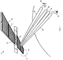
- a satellite 10 is shown in orbit and includes a phased array antenna system 12 that is capable of producing multiple beams.
- Phased array antenna system 12 includes four apertures 14, 16, 18 and 20.
- apertures 18 and 20 are shown producing four distinct beams 22, 24, 26, and 28.
- Each of these beams may be used for transmitting and/or receiving electromagnetic signals to and from locations respectively covered by phased array antenna system 12.
- beam 22 may be used to receive an electromagnetic signal (e.g., a radio frequency (RF) signal, etc.) that is transmitted from a ground station 30 that is covered by beam 22.
- RF radio frequency
- phased array antenna system 12 or a portion of the phased array antenna system is designed to operate at one or more frequencies (e.g., C - band, Ku - band, etc.) within the electromagnetic spectrum in which ground station 30 transmits. Additionally, phased array antenna system 12 may be designed to receive electromagnetic signals with one or more polarizations.
- phased array antenna system 12 or a portion of the phased array antenna system may be designed to operate with polarizations such as linear polarizations (e.g., vertical, horizontal, etc.), circular polarization (e.g., right hand circular, left hand circular, etc.), elliptical polarization, or other similar electromagnetic polarization.
- polarizations such as linear polarizations (e.g., vertical, horizontal, etc.), circular polarization (e.g., right hand circular, left hand circular, etc.), elliptical polarization, or other similar electromagnetic polarization.
- the signal may be processed (e.g., amplified, placed in another frequency band, etc.) by hardware onboard satellite 10.
- a C - band, vertically polarized signal may be received from ground station 30 over beam 22.
- circuitry in a payload module 32 (and/or circuitry located near one or more of the radiating elements) may process the signal for transmission to another location that is covered by satellite 10.
- the signal may be amplified, mixed to a frequency within the Ku - band, and transmitted with a horizontal polarization.
- the processed signal is transmitted over beam 28 to a mobile station 34 (e.g., a car, a truck, etc.).
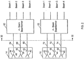
- FIG 2 a block diagram representing a portion of payload module 32 and apertures 14 and 16 are shown.
- Each aperture includes a number of antenna elements that in aggregate form the respective aperture.
- aperture 14 and aperture 16 only three elements are shown in aperture 14 and aperture 16.
- aperture 14 includes antenna elements 36, 38 and 40 while aperture 16 includes antenna elements 42, 44 and 46.
- both apertures 14 and 16 are configured to receive electromagnetic signals.
- typically platforms such as satellite 10 include phased array antennas for transmitting and receiving.
- one phased array antenna is configured to transmit at a particular frequency band (e.g., Ku, Ka, etc.) and polarization (e.g., linear polarization, etc.) and a complementary phased array antenna is configured to receive at a different frequency and orthogonal polarization.
- a particular frequency band e.g., Ku, Ka, etc.
- polarization e.g., linear polarization, etc.
- a complementary phased array antenna is configured to receive at a different frequency and orthogonal polarization.
- Each of the antenna elements e.g., elements 36 - 46
- Each antenna element 36 - 46 is respectively connected to a low noise amplifier 48, 50, 52, 54, 56, 58 that conditions the received signal prior to providing it to payload module 32.
- payload module 32 includes two conventional four-beam beamformers 60, 62 that each produce four beams from the electromagnetic signals respectively received by apertures 14 and 16. These eight beams may be steered in angular directions to cover particular geographic locations and the beam coverage areas may or may not overlap. For example, the four beams associated with four-beam beamformer 60 may be steered to locations as illustrated in FIG 1 .
- a platform such as satellite 10 may be capable of producing more than eight beams.
- satellite 10 may be capable of producing thirty-two, forty-eight, or more beams. However, for ease of illustration only eight beams are described, although the number of beamformers and beamformer components is scalable to produce additional beams for transmission and/or reception of electromagnetic signals.
- respective conductors 64, 66, 68, 70, 72 and 74 provide the signals from low noise amplifiers 48 - 58 to conventional four-beam beamformers 60, 62.
- the signals may be adjusted prior to being received at the beamformers.
- the signals may be mixed to an intermediate frequency (IF) prior to being processed by the beamformers.
- IF intermediate frequency
- the signals may also be converted into another portion of the electromagnetic spectrum for processing by the beamformers.
- the signals from low noise amplifiers 48 - 58 may be converted into optical signals prior to being provided to beamformers 60 and 62.
- FIG 3 a block diagram of four-beam beamformer 60, which is dedicated to aperture 14, is shown.
- four beams are produced from signals provided by the antenna elements in aperture 14.
- Each respective beam is produced by an individual beamformer 76, 78, 80, 82. Since each of the four beamformers 76,78, 80, 82 have identical components, a description of one beamformer (e.g., beamformer 76) is provided to commonly describe all four of the beamformers.
- phase shifts (and/or in some situations, attenuations) are respectively applied to the signals received at the phased array antenna elements 36, 38, 40. By adjusting these phase shifts (and/or attenuations) the phase front of the aggregated antenna elements is steered to a particular angular direction.
- phased array antenna element 36 to demonstrate the processing by four-beam beamformer 60; low noise amplifier 48 provides the received electromagnetic signal conductor 64 to a 2-way power divider 84 that is included in payload module 32.
- 2-way power divider 84 splits the received signal and provides the signal to 2-way power divider 86 over conductor 88.
- the signal is also provided to 2-way power divider 90 over conductor 92.
- each signal is used to produce the four independent beams in beamformers 76, 78, 80, 82. In other scenarios the signals may be further divided to produce more than four beams (e.g., eight beams, sixteen beams, etc.).
- Conductors 94, 96, 98 and 100 respectively provide the four split signals to beamformers 76, 78, 80, and 82. Similarly signals from antenna elements 38 and 40 are split and sent to each of the beamformers. Focusing on beamformer 76, three phase shifters/attenuators 102, 104, 106 receive the signals from antenna elements 36, 38, and 40. In particular phase shifter/attenuator 102 is provided signals from antenna element 36 via conductor 94. Similarly, shifter/attenuator 104 is provided signals from antenna element 38 and shifter/attenuator 106 is provided signals from antenna element 40. Each phase shifter/attenuator 102, 104, 106 applies a phase shift to the respectively received signal.
- phase shifter/attenuator 102 may apply a 0° phase shift while phase shifter/attenuators 104 and 106 respectively apply phase shifts of 22.5° and 45°.
- phase shifts may be applied to the signals processed by beamformers 78, 80, and 82 for steering the corresponding beams.
- one or more of the phase shifter/attenuators in beamformers 76, 78, 80, and 82 may apply an attenuation or a phase shift and an attenuation to steer and/or shape the beams.
- each phase-shifted signal is provided to a three-way combiner 108 included in the beamformer.
- Combiner 108 produces a beam (i.e., beam 1) by combining the phased shifted signals from each antenna element.
- three-way combiner 108 may combine signals from antenna elements 36, 38, 40 to produce and steer a beam in a direction based on the relative phase shift of each path.
- three-way combiners 110, 112, 114 in respective beamformers 78, 80, and 82 may receive signals from the each antenna element that have been phase shifted by amounts to produce and steer the other three beams (i.e., beams 2, 3, and 4).
- This figure shows the components included in four-beam beamformer 60, which is dedicated to antenna aperture 14.
- antenna apertures 16, 18, and 20 are connected to dedicated beamformers that accordingly divide received signals and apply one or more phase shifts (and/or attenuations).
- dedicated beamformers By implementing these dedicated beamformers, a fixed number of beams are allocated to each aperture. In this example, the allocation of the four beams (produced by 3-way combiners 108, 110, 112, and 114) are fixed. Thereby, if phased array antenna aperture 16 is oriented such that it can provide better coverage, beams can not be reallocated from phased array antenna aperture 14 to aperture 16. Furthermore, if aperture 14 is at an angular position that provides no useful coverage, the beams allocated to aperture 14 are wasted.
- antenna aperture 14 may be facing westward and phased array antenna 16 may be facing eastward while satellite 10 is in low earth orbit.
- signal traffic may be dominant in the west in comparison to the east.
- the beam allocation is fixed, appropriate westward coverage may not be provided and the eastward pointing beams may be underutilized.
- fixed beam allocation may provide inappropriate coverage based on transmit and/or reception beam parameters (e.g., frequency, polarization, etc.).
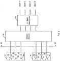
- a portion of payload module 32 is shown to include one four-beam beamformer 116 that is shared among antenna elements of phased array antenna apertures 14 and 16.
- the number of hardware components is reduced, which correspondingly reduces the cost and weight of payload module 32.
- the pool of beams produced by the beamformer may be flexibly allocated among the phased array antenna apertures depending upon the orientation of satellite 10 (or other type of platform), signal traffic volume, or beam parameter (e.g., frequency, polarization, etc.).
- more beams may be allocated to the westward facing aperture by re-allocating beams currently assigned to the eastward facing aperture. At a later time some or all of the beams may be returned for eastward coverage by re-allocating the beams to the eastward facing phased array antenna aperture.
- apertures 14 and 16 share four-beam beamformer 116, which produces four steerable beams (i.e., Beam 1, Beam 2, Beam 3, Beam 4) that may be allocated among the apertures.
- apertures 14 and 16 respectively include three array elements (i.e., antenna elements 36, 38, 40 and antenna elements 42, 44, 46) for illustrative purposes.
- Low noise amplifiers 48 - 58 respectively connect to antenna elements 36 - 46 and condition received electromagnetic signals.
- a selector network 118 selects which signals are provided to the four-beam beamformer.
- the selector network 118 can take a variety of forms, such as selector network 118A in FIG 5 or selector network 118B in FIG 6 . By being capable to select signals from antenna elements 36 - 40, all four beams may be allocated to provide coverage for aperture 14. At a different time, or when satellite 10 is in a different position, selector network 118 may be configured to beamform signals received by antenna element 42 - 46 to provide coverage for aperture 16.
- two beams may be allocated to aperture 14 and the other two beams (e.g., beam 3 and beam 4) may be allocated to aperture 16.
- beamformer sharing reduces the number of beamformer components in payload module 32. By reducing the number of components, the mass of payload module 32 along with the cost are correspondingly reduced.
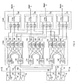
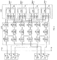
- beamformer 116 takes the form of beamformer 116A.
- Both apertures 14 and 16 include components (e.g., antenna elements 36 - 46 and low noise amplifiers 48 - 58) that are shown in FIG 4 .
- Conductors 120, 122, 124, 126, 128, 130 connect the low noise amplifiers to selector network 118A.
- array element 36 is connected to a 4-way power divider 132
- array element 38 is connected to a 4-way power divider 134
- array element 40 is connected to 4-way power divider 136.
- array element 42 is connected to another 4-way power divider 138, array element 44 is connected to 4-way power divider 140, and array element 46 is connected to 4-way power divider 142.
- Signals from each antenna element are four-way divided so that each signal may be selected for phasing shifting (and/or attenuating) to produce each of the four beams.
- Selector network 118A is used to select which antenna elements provide signals to produce the four beams.
- the four beams may be allocated to either one or more of the phased array antenna apertures 14, 16. For example, all four beams may be allocated to aperture 14 during periods of heavy communication traffic in the area covered by aperture 14. At other times, one, two, three, or four of the beams may be allocated to aperture 16 to increase link capacity for the area covered by phased array antenna 16.
- selector network 118A includes twelve 2-way selectors 144, 146, 148, 150, 152, 154, 156, 158, 160, 162, 164 and 166.
- signals from each of the antenna elements may be selected to produce one or more of the four beams.
- four-beam beamformers 116A includes four single-beam beamformers 168, 170, 172, 174.
- 2-way selectors 144, 146, 148, and 150 are assigned to select between antenna elements 36 and 42.
- Antenna elements 38 and 44 are assigned to 2-way selectors 152, 154, 156 and 158 while antenna elements 40 and 46 are assigned to 2-way selectors 160, 162, 164, and 166.
- the 2-way selectors By controlling the 2-way selectors, signals received from all or a subset of the antenna elements are beamformed to produce the four beams.
- the 2-way selectors connected to a common beamformer are placed in the same position.
- 2-way selectors 144, 152 and 160 (which are all connected to beamformer 168) are placed in the same position so that signals from the same aperture are provided to beamformer 168.
- 2-way selectors 146, 154, 162 are typically placed in the same position and 2-way selectors 148, 156, 164 are also placed in the same position.
- 2-way selectors 150, 158, and 166 are typically placed in the same position to beamform signals from the same aperture.
- 2-way selectors 144 - 166 may be placed in appropriate positions to beamform signals from antenna elements in aperture 14. By selecting signals from the aperture 14, all four beams are allocated to provide coverage for aperture 14. At a different time, or when satellite 10 is in a different position, 2-way selectors 144 - 166 may be placed in appropriate positions to beamform signals received by antenna element 42, 44, 46. By selecting signals from these antenna elements in aperture 16, all four beams are now allocated to provide coverage for aperture 16. In still another example, one beam (e.g., beam 1) may be allocated to aperture 14 and the other three beams (e.g., beam 2, 3 and 4) may be allocated to aperture 16.
- beam 1 e.g., beam 1
- the other three beams e.g., beam 2, 3 and 4
- beamformers 168, 170, 172, and 174 include phase shifter/attenuators that phase shift (and/or attenuate) the signals. After applying a phase shift and/or an attenuation, the signals are provided to corresponding 3-way combiners that are included in each beamformer 168, 170, 172, and 174. By combining the signals from the phase shifter/attenuators, the four 3-way combiners respectively produce beams 1,2, 3 and 4.
- selector network 118A includes 2-way selectors to respectively share the beamformers 168 - 174 among the antenna elements in phased array antenna apertures 14 and 16.
- one or more of the selectors may be a 3-way, 4-way, or N-way selectors (where N is any integer number) to allow for more antenna apertures to share the beamformers.
- Various techniques may be used to implement the 2-way, 3-way, or N-way selectors.
- switches may provide the selection function.
- other switching techniques known to one skilled in the art of telecommunications and electronics may be incorporated. For example, semiconductor switches, ferrite switches, switches fabricated with micro-electro-mechanical systems (MEMS), digital switches, etc.
- MEMS micro-electro-mechanical systems
- the selection function may also be provided by one or more processors (e.g., digital signal processors, microprocessors, etc.) that execute appropriate instructions.
- the 2-way selectors are used to select from the electromagnetic signals received by antenna elements 36 - 46.
- the signals collected at the antenna elements may be converted prior to being provided to the selector networks.
- the signals may be converted into optical signals and provided to optical switches included in the selector networks.
- each selector is a single 2-way selector, however in some arrangements one or more of the selectors may be implemented by a network of multiple switches or a network of other types of selector devices.
- beamformers 168 - 174 are implemented with discrete components (e.g., phase shift/attenuators, 3-way combiners, etc.). In other arrangements, the discrete components may be integrated into a single package. For example, all of the components included in beamformer 168 may be integrated into a single package (e.g., an optical-electronic integrated package, an RF integrated package, etc.) or other type of integrated assembly.
- the selector network 118 e.g., selector network 118A or 118B
- a portion of the selector network may be integrated into a single package.
- beamformer sharing reduces the number of components in payload module 32.
- the shared beamformers include less hardware components.
- the mass of payload module 32 along with the cost are correspondingly reduced.
- beamformers may be shared such that the beams allocated to a phased array antenna aperture are constrained to a group size.
- an aperture may be constrained such that beams are allocated in groups of two. So, using this constraint, e.g., zero, two, or four beams may be allocated to each of the phased array antenna apertures.
- signal dividers e.g., power dividers
- selector network 118B the selector network
- a signal divider is respectively inserted between each selector (in selector network 118B) and each phase shifter/attenuator (in four - beam beamformer 116A).
- payload module 32 includes 2-way power dividers that connect the selector network 118B to the phase shifter/attenuators included the beamformers 168, 170, 172, and 174.
- 2-way power dividers 178, 180, 182, 184, 186 and 188 respectively connect 2-way selectors 190, 192, 194, 196, 198, 200 to the phase shift/attenuators included in beamformers 168, 170, 172, and 174.
- each phased array antenna aperture is constrained to groups of N beams (e.g., 0N, N, 2N, 3N, etc.).
- two two-beam groups are allocated between aperture 14 and aperture 16. For example, say both two-beam groups (for a total of all four beams) are allocated to aperture 14.
- signals received by antenna elements 36, 38, and 40 are provided (via low noise amplifiers 48, 50, 52) to respective 2-way power dividers 202, 204, and 206.
- the signals are split by the power dividers and are provided to 2-way selectors 190 - 200.
- the split signals are provided to two 2-way power dividers 178 - 188 and the corresponding phase shifters/attenuators of beamformers 168, 170,172 and 174.
- two groups of two beams are allocated to aperture 14.
- 2-way selectors 190 - 200 in appropriate selection positions, signals received at antenna element 42, 44, and 46 (and sent via low noise amplifiers 54, 56 58 and 2-way power dividers 208, 210, 212) are provided to 2-way power dividers 178 - 188 and then to the phase shifters/attenuators in beamformers 168, 170, 172, and 174.
- the signals are provided to the 3-way combiners to produce and allocate all four beams (i.e., beams 1, 2, 3, and 4) to aperture 16.
- Selector network 118A shown in FIG 5 allowed four beams to be individually allocated between phased array antenna apertures 14 and 16. For example, all four beams could be allocated to aperture 14 or to aperture 16. Alternately, one, two, or three beams may be allocated to aperture 14 or aperture 16 (so long as the sum of the allocated beams does not exceed four).
- selector network 118B in FIG 6 constrains beam allocation to particular groups of beams. As shown in FIG 6 , network selector 118B includes 2-way power dividers 178 - 188 to constraint beam allocation to groups of two. For example, four beams (two groups of two beams) may be allocated to aperture 14 or to aperture 16.
- one group of two beams may be allocated to aperture 14 and another group of two beams (e.g., beams 3 and 4) may be allocated to aperture 16.
- selector network 118 may be extended to allocate more individual beams or groups of beams. For example, from a pool of N beams (e.g., sixteen beams, thirty-two beams, forty-eight beams, etc.), a selector network may be implemented such that the N beams are flexibly allocated among phased array antenna apertures. For example, the N beams may be evenly or unevenly distributed among the apertures. During particular time periods more beams may be allocated to a particular aperture to provide needed coverage for increased signal traffic.
- beams may be allocated in groups that may or may not be constrained to one group size. For example, groups of one, two, three, or four beams may be designated for allocation. Furthermore, multiple group sizes may be implemented that may be similar or dissimilar in size. Along with constraining beam groups to a particular number, grouping may also be constrained by one or more other parameters. For example, beams may be grouped by frequency band (e.g., C-band, Ku-band, etc.), polarization (e.g., liner vertical, linear horizontal, right hand circular, left hand circular, elliptical, etc.), or one or more other parameters.
- frequency band e.g., C-band, Ku-band, etc.
- polarization e.g., liner vertical, linear horizontal, right hand circular, left hand circular, elliptical, etc.
- a table 214 is shown that compares the approximate number of components included in an antenna system using dedicated beamformers (e.g., beamformers 76, 78, 80, 82 shown in FIG 3 ) to the number of components included in an antenna system using shared beamformers (e.g., beamformers 168, 170, 172 and 174 shown in FIG 5 ).
- variables are respectively assigned to parameters associated with the components.
- the letter “L” is defined as the number of phased array antenna apertures and the letter “M” is defined as the number of elements in each phased array antenna aperture.
- the letter “N” is defined as maximum number of beams. "N” can also be considered as the total number of beams in the beam pool. Completing the variables is the letter "P”, which defines the number of beams constrained in a group that may be allocated to each phased array antenna aperture.
- Column 216 of table 214 presents the number of components used by an antenna system using dedicated beamformers.
- a total of L multiplied by M antenna elements (represented as LM) are distributed among the phased array antenna apertures and are each connected to one N/P-way power divider.
- a total of LMN/P P-way power dividers are also included in the dedicated beamformers along with LMN phase shifter/attenuators.
- LN M-way combiners are included in the dedicated beamformers.
- Column 218 of table 214 presents the number of components used by an antenna system that includes a selector network for sharing beamformers such as beamformers 168, 170, 172, and 174 shown in FIG 5 and FIG 6 .
- the number of total antenna elements (LM) and N/P-way power dividers (LM) used by the antenna system that shares beamformers is equivalent to the number used by the antenna system with dedicated beamformers.
- LM total antenna elements
- LM N/P-way power dividers
- selectors e.g., switches
- MN/P L-way selectors are included in antenna system that shares beamformers.
- MN/P P-way power dividers, MN phase shifter / attenuators, and N M-way combiners are used to produce and allocate the N beams in an antenna system that shares beamformers.
- Column 222 of Table 214 presents the number of components added by implementing a shared beamformer scheme as opposed to a dedicated beamformer scheme.
- MN/P selectors are added by sharing beamformers. However, these additional selectors are less in number than the components eliminated, as shown in column 220.
- signals may be selected for transmission over one or more phased array antenna elements.
- the shared beamformers are designed for transmission.
- Combiners e.g., 3-way signal combiner 168
- the low noise amplifiers e.g., low noise amplifier 48
- power amplifiers to drive the phased array antenna elements.
- shared beamformers may provide both signal transmission and reception capabilities.
- both shared and dedicated beamformers may be implemented into a phased array antenna system. Beamformer sharing may also depend upon a signal parameter. In one configuration, beams may be shared based on signal frequency or polarization. For example, eight beams may be shared among apertures that transmit or receive Ka-band signals while only four beams are shared among apertures that transmit or receive Ku-band signals. Various types of antenna elements may be implemented in the antenna systems that included a selector network to share beams. Also, multi-beam phased arrays, multi-beam reflector arrays, or other types of antenna elements or apertures that are well known to one skilled in the art or antenna and antenna system design may be implemented. By implementing a shared beamformer, beams may be shared among different size arrays.
- beams may be shared between one aperture that includes a large number of antenna elements and another aperture that includes relatively fewer antenna elements.
- a shared beamformer may be implemented to share beams among antenna elements or groups of antenna elements that are all included in the same phased array antenna aperture.
- a selector network may be implemented to share beamformers among other signal processing modules.
- a selector network may be used to select a group of beams (from a plurality of beam groups) for further processing. Once selected, the beam group may, for example, be further beamformed to focus on a particular region that is covered by the group of beams.
- an illustrative map 224 of the United States represents coverage provided, for example, by a phased array antenna system of a satellite.
- two regions of the country are covered by respective groups of beams.
- three relatively broad beams 226, 228, and 230 are produced by the satellite phased array system.
- aperture 14 produces beams 226-230, which combined produce a beam cluster that provides partial coverage for a field of view 232 associated with the aperture.
- aperture 16 of the phased array system provides coverage to the northeast portion of the United States.
- three broad beams 234, 236, and 238 produce a beam cluster that provides partial coverage for a field of view 240 associated with aperture 16.
- a beamformer may be shared by the phased array system of the satellite.
- the beams produced by the phased array system may be allocated, e.g., for East Coast and West Coast coverage. For example, three or more beams may be allocated for West Coast coverage to produce beam cluster 232 and three or more may be allocated for East Coast coverage to produce beam cluster 240.
- a second beamformer stage may be incorporated to beamform a plurality of the beams included in one or more of the beam clusters.
- beam 226 is beam formed to produce narrow beams 242, 244, 246. These narrow beams 242-246 may be steered to focus on a region in which communication traffic is particularly heavy. However, the steering of each narrow beam is constrained to the coverage area provided by beam 226.
- additional beamforming may also be performed on the beams 228 and 230. For this particular illustration, beam 228 is beamformed to produce narrow beams 248 and 250 while beam 230 is beamformed to produce narrow beams 252, 254, and 256.
- beam 236 and 238 are beamformed to respectively produce narrow beams 258, 260, 262 and 264.
- Each of these narrow beams 242 - 264 may be steered for covering any location within the respective broader beam that is used to produce the narrow beam.
- narrow beam 260 may be steered to any location that is covered by beam 238.
- beam 258 may be steered to any location that is covered by beam 236.
- a second beamforming stage may be shared such that some or all of the beams in a beam cluster may be selectively beamformed to produce one or more beams with relatively narrow beamwidths such as beams 242-264.
- each beam cluster includes three broad beams (e.g., beams 226, 228, 230 and beams 234, 236, 238). However, more or less beams may be included in either or both clusters.
- the narrow beams formed by the second beamforming stage may be flexibly allocated between the broad beams (e.g., 226, 228, 230, 234, 236, 238). For example, six beams may be allocated to beam cluster 232 and only two beams may be allocated to beam cluster 240. By connecting beams included in the clusters of beams, one or more narrow beams may be produced (by a beamforming stage) and steered to any direction within the coverage area of the broader beam from which the narrow beam is produced.
- phased array apertures with various characteristics may be implemented to produce the cluster of beams in field of view 232 and/or 240.
- apertures that operate with various frequencies and polarizations may be implemented. Some apertures may operate with different frequencies and/or polarizations and may be pointed to the same or different geographic areas (e.g., Vertical polarization and horizontal polarization for a GEO satellite). Alternatively, apertures may operate with a similar frequency and/or polarization and be pointed the same or different geographic areas (e.g., east and west of a LEO spacecraft).
- a first beamforming stage may take the form of one or more cluster formers 268 and 270 and a second beamformer stage 272 may take the form of beamformer 116 above, as examples.
- a selector network 266 is used in a similar manner to share a beamformers for beam allocation (as described above).
- selector network 266 respective elements 36-46 included in apertures 14 and 16 are connected to cluster-formers 268 and 270. In particular, the elements are connected to the cluster-formers via low noise amplifiers 48-58.
- cluster-formers 268 and 270 combine signals from the respective antenna elements to produce one or more relatively broad beams.
- beam-cluster 268 may use signals received by aperture 14 to produce beams 226-230.
- signals received by aperture 16 may be preferably provided to cluster-former 270 to produce beams 234-238.
- a second beamformer 272 may be used to produce one or more second beams from the beam clusters.
- beams produced by cluster-former 268 e.g., beams 226-230
- beams produced by cluster-former 270 e.g., beams 234-2308
- beams produced by cluster-former 270 may also be beamformed by beamformer 272 to produce one or more second beams (e.g., beam 258-264) that may be steered within the coverage area of the respective aperture from which they are produced.
- selector network 266 By incorporating selector network 266 between cluster-formers 268 and 270 and the second beamforming stage 272, signals from an appropriate cluster-former are provided to the second beamformer.
- East Coast communication traffic may be heavier in the morning (than West Coast communication traffic) due to time zone differences.
- signals from cluster-former 270 may be provided to second beamforming stage 272.
- selector network 266 may be remotely controlled (e.g., via an RF link) to provide the signals from cluster-former 270 to beamformer 272.
- late afternoon communication traffic on the West Coast may be significantly heavier than communication traffic on the East Coast.
- selector network 266 may preferably provide signals from cluster-former 268 to second beamforming stage 272.
- beamformer 272 includes N outputs (designated as beam 1, beam 2, ..., beam N) that may be used to provide second beams to other components and/or equipment (e.g., a receiver, etc.) included in the satellite (or other similar platform).
- this illustrative design includes two cluster-formers 268, 270, one selector network 266, and one second beamforming stage 272, in other designs, the number of select networks, cluster-formers, and beamformers may be scaled to accept signals from more or less elements and/or phased array apertures.
- second beamforming stage 272 is shared among cluster-former 268 and cluster-former 270.
- the number of hardware components is reduced, which correspondingly reduces the cost and weight of a payload module such as payload module 32.
- the beams from cluster-formers 268, 270 may be selected depending upon signal traffic volume or another parameter (e.g., frequency, polarization, etc.).
- selector network 266 was positioned between the set of cluster-formers 268, 270 and the second beamforming stage 272.
- one or more selector networks may be arranged in a different manner.
- selector network 266 may be similar to selector network 118 (e.g., selector 118A or 118B shown in FIGS. 5 and 6 , respectively).
- Selector network 266 may select between beam clusters created by one or more apertures. Switching operations of selector network 266 are performed in a manner such that the signals combined by beamformer stage 272 are from beam clusters produced by the same aperture and are steered in the same direction.
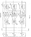
- cluster-former 274 provides a first beamforming stage that uses signals received from an aperture (such as aperture 14) to produce one or more relatively broad beams.
- signals received from elements 36, 38, and 40 are provided to respective power dividers 280, 282, and 284.
- three power dividers are incorporated into cluster former 274, however, in other arrangements additional power dividers may be incorporated.
- Each of the power dividers split their respective input signals dependent upon the number of beams to be formed.
- each power divider performs a three-way split of their respective input signals for forming three broad beams.
- This splitting is scalable for producing more or less board beams.
- the split signals from each power divider are respectively provided to phase-shifters/ attenuators 286, 288, 290, 292, 294, 296, 298, 300 and 302 that may individually attenuate (represented by ⁇ ) and/or adjust the phase (represented by ⁇ ) of the input signal.
- attenuation and phase adjustments are performed to produce and steer the one or more broad beams.
- adjusted output signals of the phase-shifters/ attenuators are provided to respective power combiners 300, 302, and 304.
- each beam a signal received by each element 36-40 is provided to each power combiner.
- phase-shifter/ attenuator 286 provides a signal that is received from element 36 while phase-shifters/ attenuators 292 and 298 respectively provide signals from elements 38 and 40.
- These three signals are combined in power combiner 300.
- Each of the power combiners combine the attenuated and/or phase shifted input signals to produce a broad beam.
- the number of power combiners may be increased or decreased to produce more or less broad beams.
- various designs may be implemented to select signals for initial beamforming and subsequent beamforming.
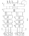
- signals are received from respective element groups in apertures 14 and 16 in a similar manner as described in regards to the apertures shown FIG. 9 .
- Cluster-formers 306 and 308 respectively receive and beamform the signals to produce one or more beam clusters.
- Signals representing the beams produced by the cluster-formers are provided to respective selector networks 310 and 312 that select signals to additional beamforming.
- Second beamforming stages 314 and 316 produce one or more second beams that are passed to another selection network 318 that provides another round of selection. These second beams may be steered to any angular direction within coverage area provided by the respective aperture used to produce the second beam(s).
- selector network 318 may provide these selected beams to other equipment and/or components for additionally processing.
- a plurality of second beams are provided to another beamforming stage 320 that produces one or more final beams.
- the beams that are output from beamforming stage 320 may be steered. However, these beams are also constrained to the coverage area of the respective aperture used to produce the final beams.
- a selector network may be used to share a beamformer for allocating a pool of beams among clusters of beams. Thereby, if one cluster provides better coverage (e.g., for a high traffic situation), more beams may be allocated to that cluster. Later, when another cluster is providing more useful coverage, the selector network may re-allocate the beams to this other cluster. Furthermore, by sharing a beamformer among two or more cluster-formers, the number of hardware components is reduced, which correspondingly reduces the cost and weight of the payload module.
- the pool of beams produced by the beamformer may be flexibly allocated among the clusters depending upon issues such as orientation the satellite (or other type of platform), signal traffic volume, or beam parameter (e.g., frequency, polarization, etc.), etc.
- the number of beams allocated to a beam cluster may be constrained to a particular group size.
- a beam cluster may be constrained such that the narrow beams produced from the beam cluster are allocated in groups of two. So, using this constraint, e.g., zero, two, or four beams may be allocated to the beam cluster.
- signal dividers e.g., power dividers
- a signal divider may be included in one or more of the implemented selector networks. For example, a signal divider may be respectively inserted between each selector and each phase shifter/attenuator.
- beams may be individually allocated or may not be constrained to one group size.
- multiple group sizes may be implemented with similar or dissimilar sizes.
- grouping may also be constrained by one or more other parameters.
- beams may be grouped by frequency band (e.g., C-band, Ku-band, etc.), polarization (e.g., linear vertical, linear horizontal, right hand circular, left hand circular, elliptical, etc.), or one or more other parameters.
Landscapes
- Engineering & Computer Science (AREA)
- Physics & Mathematics (AREA)
- Astronomy & Astrophysics (AREA)
- General Physics & Mathematics (AREA)
- Remote Sensing (AREA)
- Aviation & Aerospace Engineering (AREA)
- Computer Networks & Wireless Communication (AREA)
- Signal Processing (AREA)
- Variable-Direction Aerials And Aerial Arrays (AREA)
- Aerials With Secondary Devices (AREA)
- Radio Relay Systems (AREA)
Claims (11)
- Phased-Array-Antennensystem (12), aufweisend:eine erste Strahlformungsstufe (268, 270, 306, 308) aufweisend einen ersten Bündel-Former (268, 306), der an eine erste Apertur (14) gekoppelt ist, die eine erste Menge von Phased-Array-Antennenelementen (36, 38, 40) beinhaltet, und einen zweiten Bündel-Former (270, 308), der an eine zweite Apertur (16) gekoppelt ist, die eine zweite Menge von Phased-Array-Antennenelemente (42, 44, 46) beinhaltet, wobei der erste Bündel-Former eingerichtet ist, auf Grundlage von zumindest zwei elektromagnetischen Signalen aus der ersten Menge von Phased-Array-Antennenelementen eine erste Vielzahl von ersten Antennenstrahlen (226, 228, 230) zu erzeugen, wobei der zweite Bündel-Former eingerichtet ist, auf Grundlage von zumindest zwei elektromagnetischen Signalen aus der zweiten Menge von Phased-Array-Antennenelementen eine zweite Vielzahl von ersten Antennenstrahlen (234, 236, 238) zu erzeugen, wobei die erste Vielzahl von ersten Antennenstrahlen (226, 228, 230) ein erstes Strahlenbündel erzeugt, das eine teilweise Abdeckung für ein erstes, zur ersten Apertur (14) zugehöriges Sichtfeld (232) bereitstellt, wobei die zweite Vielzahl von ersten Antennenstrahlen (234, 236, 238) ein zweites Strahlenbündel erzeugt, das eine teilweise Abdeckung für ein zweites, zur zweiten Apertur (16) zugehöriges Sichtfeld (240), bereitstellt;einen Selektor (266, 310, 312), der eingerichtet ist, zwischen der ersten Vielzahl von Antennenstrahlen und der zweiten Vielzahl von ersten Antennenstrahlen auszuwählen, um ein Bündel von ersten Antennenstrahlen einem entsprechenden Sichtfeld (232, 240) zuzuweisen, wobei das Bündel erster Antennenstrahlen aus dem ersten Strahlenbündel besteht, wenn die erste Vielzahl erster Antenennstrahlen (226, 228, 230), welche dem ersten Sichtfeld (232) entspricht, ausgewählt wird, oder das Bündel erster Antennenstrahlen aus dem zweiten Strahlenbündel besteht, wenn die zweite Vielzahl erster Antennenstrahlen (234, 236, 238), die dem zweiten Sichtfeld (240) entspricht, ausgewählt wird;
undeine zweite Strahlformungsstufe (272, 314, 316), die eingerichtet ist, das Bündel erster Antennenstrahlen von dem Selektor (266, 310, 312) zu empfangen, wobei die zweite Strahlformungsstufe (272, 314, 316) ferner eingerichtet ist, zumindest einen zweiten Antennenstrahl (242, 244, 246, 248, 250, 252, 254, 256, 258, 260, 262, 264) aus jedem Antennenstrahl in dem Bündel erster Antennenstrahlen zu erzeugen, wobei der zumindest eine zweite Antennenstrahl (242, 244, 246, 248, 250, 252, 254, 256, 258, 260, 262, 264) in einen Bereich in dem entsprechenden Sichtfeld (232, 240) gelenkt wird. - Phased-Array-Antennensystem nach Anspruch 1, wobei der zumindest eine zweite Antennenstrahl (242, 244, 246, 248, 250, 252, 254, 256, 258, 260, 262, 264) eine Lenkrichtung besitzt, die teilweise durch eine Strahlenbreite des Antennenstrahls in dem Bündel erster Antennenstrahlen beschränkt wird, aus dem der zumindest eine Antennenstrahl (242, 244, 246, 248, 250, 252, 254, 256, 258, 260, 262, 264) erzeugt wird.
- Phased-Array-Antennensystem nach Anspruch 1, wobei die erste Strahlformungsstufe einen Phasenverschieber (286, 288, 290, 292, 294, 296, 298, 300, 302) beinhaltet, der eingerichtet ist, die Phase von einem Signal anzupassen, das zu zumindest einem der empfangenen elektromagnetischen Signale gehört.
- Phased-Array-Antennensystem nach Anspruch 1, wobei die erste Strahlformungsstufe ein Dämpfungsglied (286, 288, 290, 292, 294, 296, 298, 300, 302) beinhaltet, das eingerichtet ist, ein zu zumindest einem der empfangenen elektromagnetischen Signale zugehöriges Signal zu dämpfen.
- Phased-Array-Antennensystem nach Anspruch 1, wobei der Selektor einen Schalter beinhaltet, und wobei der Schalter ein Zwei-Wege-Schalter, ein Halbleiterschalter, ein mechanischer Schalter, ein Ferritschalter, ein optischer Schalter oder ein digitaler Schalter ist.
- Phased-Array-Antennensystem nach Anspruch 1, wobei der Selektor eingerichtet ist, Anweisungen auszuführen, um Antennenstrahlen aus dem Bündel erster Antennenstrahlen auszuwählen, um diese an die zweite Strahlformungsstufe auszugeben.
- Phased-Array-Antennensystem nach Anspruch 1, wobei die erste Strahlformungsstufe, der Selektor und die zweite Strahlformungsstufe in einer integrierten Einheit beinhaltet sind.
- Verfahren zum Empfangen und/oder Senden von elektromagnetischer Strahlen in einer Phased-Array-Antenne aufweisend eine Vielzahl von Mengen von Antennenelementen (36, 38, 40, 42, 44, 46), die eingerichtet sind eine Menge von Signalen zu senden und/oder zu empfangen, das Verfahren umfassend:Erzeugen einer ersten Vielzahl von ersten Antennenstrahlen (226, 228, 230) von einem ersten Bündel-Former (268, 306) einer ersten Strahlformungsstufe (268, 270, 306, 308), die an eine erste Apertur (14) gekoppelt ist, welche eine erste Menge von Antennenelementen (36, 38, 40) beinhaltet, wobei die erste Vielzahl erster Antennenstrahlen (226, 228, 230) ein erstes Strahlenbündel erzeugt, das eine teilweise Abdeckung für ein erstes zur ersten Apertur (14) zugehöriges Sichtfeld (232) bereitstellt;Erzeugen einer zweiten Vielzahl erster Antennenstrahlen (234, 236, 238) von einem zweiten Bündel-Former (270, 308) der ersten Strahlformungsstufe, die an eine zweite Apertur (16) gekoppelt ist, welche eine zweite Menge von Antennenelementen (42, 44, 46) beinhaltet, wobei die zweite Vielzahl erster Antennenstrahlen (234, 236, 238) ein zweites Strahlenbündel erzeugt, das eine teilweise Abdeckung für ein zweites zur zweiten Apertur (16) zugehöriges zweites Sichtfeld (240) bereitstellt;Zuweisen, durch einen Selektor (266, 310, 312), eines Bündels erster Antennenstrahlen von einem der ersten Vielzahl erster Antennenstrahlen (226, 228, 230) oder der zweiten Vielzahl erster Antennenstrahlen (234, 236, 238) an Eingänge einer zweiten Strahlbildungsstufe (272, 314, 316), wobei der Selektor (266, 310, 312) zwischen der ersten Vielzahl erster Antennenstrahlen (226, 228, 230) und der zweiten Vielzahl erster Antennenstrahlen (234, 236, 238) auswählt, wobei das Bündel erster Antennenstrahlen aus dem ersten Strahlenbündel besteht, wenn die erste Vielzahl erster Antennenstrahlen (226, 228, 230), die dem ersten Sichtfeld (232) entspricht, ausgewählt wird, oder das Bündel erster Antennenstrahlen aus dem zweiten Strahlenbündel besteht, wenn die zweite Vielzahl erster Antennenstrahlen(234, 236, 238), die dem zweiten Sichtfeld (240) entspricht, ausgewählt wird; undErzeugen von zumindest einem zweiten Antennenstrahl (242, 244, 246, 248, 250, 252, 254, 256, 258, 260, 262, 264) aus jedem Antennenstrahl in dem Bündel erster Antennenstrahlen in der zweiten Strahlbildungsstufe, wobei der zumindest eine Antennenstrahl in einen Bereich in einem entsprechenden Sichtfeld (323, 240) gelenkt wird.
- Verfahren nach Anspruch 8, wobei das Erzeugen der ersten Vielzahl erster Antenennstrahlen umfasst:Empfangen von elektromagnetischen Signalen aus der ersten Menge von Antennenelementen; undStrahlformen der elektromagnetischen Signale, um die erste Vielzahl erster Antennenstrahlen (226, 228, 230) zu erzeugen, und wobei das Zuweisen das Auswählen des Bündels erster Antennenstrahlen aus der ersten Vielzahl erster Antennenstrahlen umfasst.
- Verfahren nach Anspruch 9, ferner umfassend Strahlformen von jedem Antennenstrahl in dem Bündel erster Antennenstrahlen, um den zumindest einen zweiten Antennenstrahl zu erzeugen.
- Verfahren nach Anspruch 9, ferner umfassend das Beschränken der Auswahl des Bündels erster Antennenstrahlen auf eine bestimmte Anzahl von Strahlen für das entsprechende Sichtfeld (232, 240).
Applications Claiming Priority (2)
| Application Number | Priority Date | Filing Date | Title |
|---|---|---|---|
| US11/360,532 US7511666B2 (en) | 2005-04-29 | 2006-02-24 | Shared phased array cluster beamformer |
| PCT/US2006/046358 WO2007106159A2 (en) | 2006-02-24 | 2006-12-06 | A shared phased array cluster beamformer |
Publications (3)
| Publication Number | Publication Date |
|---|---|
| EP1987567A2 EP1987567A2 (de) | 2008-11-05 |
| EP1987567A4 EP1987567A4 (de) | 2009-07-22 |
| EP1987567B1 true EP1987567B1 (de) | 2017-03-29 |
Family
ID=38509938
Family Applications (1)
| Application Number | Title | Priority Date | Filing Date |
|---|---|---|---|
| EP06849918.5A Active EP1987567B1 (de) | 2006-02-24 | 2006-12-06 | Gemeinsam benutzter phasengruppencluster-strahlformer |
Country Status (4)
| Country | Link |
|---|---|
| US (1) | US7511666B2 (de) |
| EP (1) | EP1987567B1 (de) |
| ES (1) | ES2629980T3 (de) |
| WO (1) | WO2007106159A2 (de) |
Families Citing this family (40)
| Publication number | Priority date | Publication date | Assignee | Title |
|---|---|---|---|---|
| US9084260B2 (en) | 2005-10-26 | 2015-07-14 | Intel Corporation | Systems for communicating using multiple frequency bands in a wireless network |
| US7864099B2 (en) * | 2007-07-20 | 2011-01-04 | Gm Global Technology Operations, Inc. | Low cost short range radar |
| US8208885B1 (en) * | 2009-03-18 | 2012-06-26 | Lockheed Martin Corporation | Variable time, phase, and amplitude control device |
| WO2012122060A1 (en) * | 2011-03-04 | 2012-09-13 | Visa International Service Association | Cloud service facilitator apparatuses, methods and systems |
| RU2579610C2 (ru) * | 2011-04-06 | 2016-04-10 | Открытое акционерное общество "Научно-исследовательский институт приборостроения имени В.В. Тихомирова" | Фазовый способ формирования провалов в диаграмме направленности плоской фазированной антенной решетки |
| US9780928B2 (en) | 2011-10-17 | 2017-10-03 | Golba Llc | Method and system for providing diversity in a network that utilizes distributed transceivers and array processing |
| US9116227B2 (en) * | 2012-02-22 | 2015-08-25 | Toyota Motor Engineering & Manufacturing North America, Inc. | Hybrid radar integrated into single package |
| US9197982B2 (en) | 2012-08-08 | 2015-11-24 | Golba Llc | Method and system for distributed transceivers for distributed access points connectivity |
| JP2014060616A (ja) | 2012-09-18 | 2014-04-03 | Samsung Electronics Co Ltd | 通信装置、および信号検出方法 |
| CN104781984A (zh) * | 2012-12-10 | 2015-07-15 | 英特尔公司 | 具有rf和基带波束形成的模块化天线阵列 |
| BR112015016666B1 (pt) * | 2013-02-06 | 2021-12-28 | Telefonaktiebolaget Lm Ericsson (Publ) | Arranjo de antena conectável a um transceptor, e, estação rádio base |
| US11855680B2 (en) * | 2013-09-06 | 2023-12-26 | John Howard | Random, sequential, or simultaneous multi-beam circular antenna array and beam forming networks with up to 360° coverage |
| US10270524B2 (en) * | 2014-04-15 | 2019-04-23 | Space Systems/Loral, Llc | Broadband satellite payload architecture |
| EP3136771A4 (de) * | 2014-05-12 | 2017-05-31 | Huawei Technologies Co. Ltd. | Antennensystem |
| WO2016066190A1 (en) * | 2014-10-28 | 2016-05-06 | Fraunhofer-Gesellschaft zur Förderung der angewandten Forschung e.V. | Antenna apparatus supporting adjustability of an antenna beam direction |
| US9991944B2 (en) * | 2015-01-15 | 2018-06-05 | Hughes Network Systems, Llc | High altitude platform with multibeam coverage for aero-based terminals |
| US9848370B1 (en) * | 2015-03-16 | 2017-12-19 | Rkf Engineering Solutions Llc | Satellite beamforming |
| CA2992289A1 (en) * | 2015-07-22 | 2017-01-26 | Blue Danube Systems, Inc. | A modular phased array |
| KR102568582B1 (ko) | 2015-12-29 | 2023-08-18 | 블루 다뉴브 시스템스, 인크. | 위상 어레이에서의 낮은 열 임피던스 구조 |
| US10368251B1 (en) | 2016-07-25 | 2019-07-30 | SpaceWorks Enterprises, Inc. | Satellites and satellite-based systems for ground-to-space short-burst data communications |
| WO2018064496A1 (en) * | 2016-09-30 | 2018-04-05 | Jeffrey Freedman | Providing communications coverage using hybrid analog/digital beamforming |
| US10271334B2 (en) * | 2016-12-21 | 2019-04-23 | Verizon Patent And Licensing Inc. | System and method for controlling the distribution of antenna beams between an access network and a backhaul link based on network traffic conditions |
| CN106848579A (zh) * | 2016-12-21 | 2017-06-13 | 摩比天线技术(深圳)有限公司 | 移动通信自切换波束天线系统及其天线 |
| US10321332B2 (en) | 2017-05-30 | 2019-06-11 | Movandi Corporation | Non-line-of-sight (NLOS) coverage for millimeter wave communication |
| US10840998B2 (en) * | 2017-06-21 | 2020-11-17 | Blue Digs LLC | Broadband satellite terminal |
| US10484078B2 (en) | 2017-07-11 | 2019-11-19 | Movandi Corporation | Reconfigurable and modular active repeater device |
| US10348371B2 (en) | 2017-12-07 | 2019-07-09 | Movandi Corporation | Optimized multi-beam antenna array network with an extended radio frequency range |
| US10862559B2 (en) | 2017-12-08 | 2020-12-08 | Movandi Corporation | Signal cancellation in radio frequency (RF) device network |
| US10090887B1 (en) | 2017-12-08 | 2018-10-02 | Movandi Corporation | Controlled power transmission in radio frequency (RF) device network |
| US11146323B2 (en) | 2018-02-15 | 2021-10-12 | Space Exploration Technologies Corp. | Beamformer lattice for phased array antennas |
| TW201941500A (zh) | 2018-02-15 | 2019-10-16 | 美商太空探索科技公司 | 相控陣列天線系統 |
| WO2019161101A1 (en) * | 2018-02-15 | 2019-08-22 | Space Exploration Technologies Corp. | Antenna aperture in phased array antenna systems |
| US10637159B2 (en) | 2018-02-26 | 2020-04-28 | Movandi Corporation | Waveguide antenna element-based beam forming phased array antenna system for millimeter wave communication |
| US11088457B2 (en) | 2018-02-26 | 2021-08-10 | Silicon Valley Bank | Waveguide antenna element based beam forming phased array antenna system for millimeter wave communication |
| US10931033B2 (en) * | 2019-01-23 | 2021-02-23 | Qorvo Us, Inc. | Multi-polarization millimeter wave (mmWave) transmitter/receiver architecture with shared power amplifiers |
| CN109873251A (zh) * | 2019-04-08 | 2019-06-11 | 郭长来 | 一种减少天线受到无线电磁波干扰的装置 |
| US11183758B2 (en) | 2019-07-23 | 2021-11-23 | Rockwell Collins, Inc. | System and method for active electronically scanned array with multi-band multi-beam architecture |
| US11245442B1 (en) * | 2021-03-08 | 2022-02-08 | Huawei Technologies Co., Ltd. | Method and apparatus for communication using massive-beam MIMO phased array |
| CN113938181B (zh) * | 2021-10-13 | 2024-06-28 | 湖南国天气象科技有限公司 | 一种c波段相控阵接收卫星设备及卫星探测方法 |
| EP4387118A1 (de) * | 2022-12-16 | 2024-06-19 | Nokia Solutions and Networks Oy | Hybride strahlformung für uplink-übertragung |
Citations (5)
| Publication number | Priority date | Publication date | Assignee | Title |
|---|---|---|---|---|
| US4845507A (en) * | 1987-08-07 | 1989-07-04 | Raytheon Company | Modular multibeam radio frequency array antenna system |
| US5936588A (en) * | 1998-06-05 | 1999-08-10 | Rao; Sudhakar K. | Reconfigurable multiple beam satellite phased array antenna |
| US6268835B1 (en) * | 2000-01-07 | 2001-07-31 | Trw Inc. | Deployable phased array of reflectors and method of operation |
| US6492949B1 (en) * | 2000-08-16 | 2002-12-10 | Raytheon Company | Slot antenna element for an array antenna |
| EP1328076A2 (de) * | 2002-01-11 | 2003-07-16 | Trw Inc. | Gerät und Verfahren zum Aufbau eines flexiblen sternförmigen Satelliten Kommunikationsnetz |
Family Cites Families (26)
| Publication number | Priority date | Publication date | Assignee | Title |
|---|---|---|---|---|
| US4815479A (en) | 1986-08-13 | 1989-03-28 | M/A Com, Inc. | Hyperthermia treatment method and apparatus |
| US4929956A (en) | 1988-09-10 | 1990-05-29 | Hughes Aircraft Company | Optical beam former for high frequency antenna arrays |
| US5029306A (en) | 1989-08-10 | 1991-07-02 | The Boeing Company | Optically fed module for phased-array antennas |
| US5117239A (en) | 1991-04-24 | 1992-05-26 | General Electric Company | Reversible time delay beamforming optical architecture for phased-array antennas |
| JPH05136622A (ja) | 1991-11-13 | 1993-06-01 | Mitsubishi Electric Corp | フエーズドアレイアンテナ位相測定回路 |
| US6768456B1 (en) | 1992-09-11 | 2004-07-27 | Ball Aerospace & Technologies Corp. | Electronically agile dual beam antenna system |
| US5414433A (en) * | 1994-02-16 | 1995-05-09 | Raytheon Company | Phased array radar antenna with two-stage time delay units |
| US5621752A (en) | 1994-06-23 | 1997-04-15 | Qualcomm Incorporated | Adaptive sectorization in a spread spectrum communication system |
| US5579016A (en) * | 1995-09-20 | 1996-11-26 | Trw Inc. | Phased array multiple area nulling antenna architecture |
| JPH09284047A (ja) * | 1996-04-11 | 1997-10-31 | Jisedai Eisei Tsushin Hoso Syst Kenkyusho:Kk | マルチビーム給電装置 |
| US5821752A (en) * | 1996-07-15 | 1998-10-13 | General Electric Company | Real-time RF pulse construction for NMR measurement sequences |
| US5856804A (en) * | 1996-10-30 | 1999-01-05 | Motorola, Inc. | Method and intelligent digital beam forming system with improved signal quality communications |
| JPH10256974A (ja) | 1997-03-14 | 1998-09-25 | Mitsubishi Electric Corp | 移動体衛星通信システム |
| US6125261A (en) * | 1997-06-02 | 2000-09-26 | Hughes Electronics Corporation | Method and system for communicating high rate data in a satellite-based communications network |
| JP3525426B2 (ja) | 1997-11-28 | 2004-05-10 | トヨタ自動車株式会社 | レーダ装置 |
| US6522643B1 (en) | 1999-07-21 | 2003-02-18 | Lockheed Martin Corporation | Apparatus, method, and computer program products for cell-hopping satellite communications |
| GB2399998B (en) * | 2001-02-01 | 2005-04-13 | Fujitsu Ltd | Communications systems |
| US20030206134A1 (en) | 2001-08-03 | 2003-11-06 | Erik Lier | Partially deployed active phased array antenna array system |
| US6703976B2 (en) | 2001-11-21 | 2004-03-09 | Lockheed Martin Corporation | Scaleable antenna array architecture using standard radiating subarrays and amplifying/beamforming assemblies |
| JP2003218621A (ja) | 2002-01-21 | 2003-07-31 | Nec Corp | アレーアンテナの校正装置及び校正方法 |
| US6738017B2 (en) | 2002-08-06 | 2004-05-18 | Lockheed Martin Corporation | Modular phased array with improved beam-to-beam isolation |
| US20040196203A1 (en) | 2002-09-11 | 2004-10-07 | Lockheed Martin Corporation | Partly interleaved phased arrays with different antenna elements in central and outer region |
| US7050019B1 (en) | 2002-09-11 | 2006-05-23 | Lockheed Martin Corporation | Concentric phased arrays symmetrically oriented on the spacecraft bus for yaw-independent navigation |
| US20040061644A1 (en) | 2002-09-11 | 2004-04-01 | Lockheed Martin Corporation | CCE calibration with an array of calibration probes interleaved with the array antenna |
| US6906665B1 (en) * | 2002-11-15 | 2005-06-14 | Lockheed Martin Corporation | Cluster beam-forming system and method |
| JP4190335B2 (ja) | 2003-04-03 | 2008-12-03 | 富士通テン株式会社 | レーダ装置及びその信号処理方法 |
-
2006
- 2006-02-24 US US11/360,532 patent/US7511666B2/en not_active Expired - Lifetime
- 2006-12-06 WO PCT/US2006/046358 patent/WO2007106159A2/en not_active Ceased
- 2006-12-06 EP EP06849918.5A patent/EP1987567B1/de active Active
- 2006-12-06 ES ES06849918.5T patent/ES2629980T3/es active Active
Patent Citations (5)
| Publication number | Priority date | Publication date | Assignee | Title |
|---|---|---|---|---|
| US4845507A (en) * | 1987-08-07 | 1989-07-04 | Raytheon Company | Modular multibeam radio frequency array antenna system |
| US5936588A (en) * | 1998-06-05 | 1999-08-10 | Rao; Sudhakar K. | Reconfigurable multiple beam satellite phased array antenna |
| US6268835B1 (en) * | 2000-01-07 | 2001-07-31 | Trw Inc. | Deployable phased array of reflectors and method of operation |
| US6492949B1 (en) * | 2000-08-16 | 2002-12-10 | Raytheon Company | Slot antenna element for an array antenna |
| EP1328076A2 (de) * | 2002-01-11 | 2003-07-16 | Trw Inc. | Gerät und Verfahren zum Aufbau eines flexiblen sternförmigen Satelliten Kommunikationsnetz |
Also Published As
| Publication number | Publication date |
|---|---|
| US7511666B2 (en) | 2009-03-31 |
| US20090009392A1 (en) | 2009-01-08 |
| EP1987567A2 (de) | 2008-11-05 |
| ES2629980T3 (es) | 2017-08-17 |
| WO2007106159A3 (en) | 2008-12-18 |
| WO2007106159A2 (en) | 2007-09-20 |
| EP1987567A4 (de) | 2009-07-22 |
Similar Documents
| Publication | Publication Date | Title |
|---|---|---|
| EP1987567B1 (de) | Gemeinsam benutzter phasengruppencluster-strahlformer | |
| US7180447B1 (en) | Shared phased array beamformer | |
| US12438581B2 (en) | Multi-beam phased array antenna with disjoint sets of subarrays | |
| RU2162260C2 (ru) | Антенная система | |
| CN108390703B (zh) | 一种多波束相控阵天线机构 | |
| EP3213371B1 (de) | Antennenvorrichtungsunterstützende anpassbarkeit einer antennenstrahlrichtung | |
| JP3321126B2 (ja) | フェーズド・アレイ・アンテナ・システム及びその動作方法 | |
| US20040077379A1 (en) | Wireless transmitter, transceiver and method | |
| WO2004073111A1 (en) | Feed network for simultaneous generation of narrow and wide beams with a rotational-symmetric antenna | |
| JPH04319804A (ja) | 1以上の幅及び/又は方向を変更可能なビームを有するアンテナの放射パターンの電子制御装置 | |
| WO2002035650A1 (en) | Phase-only reconfigurable multi-feed reflector antenna for shaped beams | |
| US6295026B1 (en) | Enhanced direct radiating array | |
| CN113906632B (zh) | 一种天线及基站 | |
| EP1523785B1 (de) | Antenne mit gemeinsamer öffnung | |
| JPH1079696A (ja) | 再構築可能なサービス・エリアを有する静止通信衛星システム | |
| US5563609A (en) | Antenna system with plural beam sequential offset | |
| KR101859867B1 (ko) | 밀리미터파 안테나 장치 및 렌즈를 이용하여 빔을 생성하는 방법 | |
| EP3654544A1 (de) | Rekonfigurierbares mehrstrahl-antennensystem | |
| US20240405854A1 (en) | Method and Apparatus for Beam-Group Steering | |
| JPH08340209A (ja) | アレーアンテナ | |
| GB2317056A (en) | Signal processor system for a phased array antenna |
Legal Events
| Date | Code | Title | Description |
|---|---|---|---|
| PUAI | Public reference made under article 153(3) epc to a published international application that has entered the european phase |
Free format text: ORIGINAL CODE: 0009012 |
|
| 17P | Request for examination filed |
Effective date: 20080801 |
|
| AK | Designated contracting states |
Kind code of ref document: A2 Designated state(s): AT BE BG CH CY CZ DE DK EE ES FI FR GB GR HU IE IS IT LI LT LU LV MC NL PL PT RO SE SI SK TR |
|
| AX | Request for extension of the european patent |
Extension state: AL BA HR MK RS |
|
| R17D | Deferred search report published (corrected) |
Effective date: 20081218 |
|
| RIC1 | Information provided on ipc code assigned before grant |
Ipc: H01Q 3/02 20060101AFI20090115BHEP |
|
| A4 | Supplementary search report drawn up and despatched |
Effective date: 20090622 |
|
| RIC1 | Information provided on ipc code assigned before grant |
Ipc: H01Q 25/00 20060101ALI20090616BHEP Ipc: H01Q 3/30 20060101ALI20090616BHEP Ipc: H01Q 3/02 20060101AFI20090115BHEP |
|
| 17Q | First examination report despatched |
Effective date: 20090917 |
|
| DAX | Request for extension of the european patent (deleted) | ||
| REG | Reference to a national code |
Ref country code: DE Ref legal event code: R079 Ref document number: 602006052145 Country of ref document: DE Free format text: PREVIOUS MAIN CLASS: H01Q0021200000 Ipc: H01Q0003300000 |
|
| GRAP | Despatch of communication of intention to grant a patent |
Free format text: ORIGINAL CODE: EPIDOSNIGR1 |
|
| RIC1 | Information provided on ipc code assigned before grant |
Ipc: H01Q 1/28 20060101ALI20161006BHEP Ipc: H01Q 3/30 20060101AFI20161006BHEP Ipc: H01Q 25/00 20060101ALI20161006BHEP Ipc: H01Q 3/24 20060101ALI20161006BHEP |
|
| INTG | Intention to grant announced |
Effective date: 20161107 |
|
| GRAS | Grant fee paid |
Free format text: ORIGINAL CODE: EPIDOSNIGR3 |
|
| GRAA | (expected) grant |
Free format text: ORIGINAL CODE: 0009210 |
|
| AK | Designated contracting states |
Kind code of ref document: B1 Designated state(s): AT BE BG CH CY CZ DE DK EE ES FI FR GB GR HU IE IS IT LI LT LU LV MC NL PL PT RO SE SI SK TR |
|
| REG | Reference to a national code |
Ref country code: GB Ref legal event code: FG4D |
|
| REG | Reference to a national code |
Ref country code: CH Ref legal event code: EP |
|
| REG | Reference to a national code |
Ref country code: AT Ref legal event code: REF Ref document number: 880544 Country of ref document: AT Kind code of ref document: T Effective date: 20170415 |
|
| REG | Reference to a national code |
Ref country code: IE Ref legal event code: FG4D |
|
| REG | Reference to a national code |
Ref country code: DE Ref legal event code: R096 Ref document number: 602006052145 Country of ref document: DE |
|
| PG25 | Lapsed in a contracting state [announced via postgrant information from national office to epo] |
Ref country code: FI Free format text: LAPSE BECAUSE OF FAILURE TO SUBMIT A TRANSLATION OF THE DESCRIPTION OR TO PAY THE FEE WITHIN THE PRESCRIBED TIME-LIMIT Effective date: 20170329 Ref country code: GR Free format text: LAPSE BECAUSE OF FAILURE TO SUBMIT A TRANSLATION OF THE DESCRIPTION OR TO PAY THE FEE WITHIN THE PRESCRIBED TIME-LIMIT Effective date: 20170630 Ref country code: LT Free format text: LAPSE BECAUSE OF FAILURE TO SUBMIT A TRANSLATION OF THE DESCRIPTION OR TO PAY THE FEE WITHIN THE PRESCRIBED TIME-LIMIT Effective date: 20170329 |
|
| REG | Reference to a national code |
Ref country code: NL Ref legal event code: MP Effective date: 20170329 |
|
| REG | Reference to a national code |
Ref country code: AT Ref legal event code: MK05 Ref document number: 880544 Country of ref document: AT Kind code of ref document: T Effective date: 20170329 |
|
| REG | Reference to a national code |
Ref country code: ES Ref legal event code: FG2A Ref document number: 2629980 Country of ref document: ES Kind code of ref document: T3 Effective date: 20170817 |
|
| PG25 | Lapsed in a contracting state [announced via postgrant information from national office to epo] |
Ref country code: BG Free format text: LAPSE BECAUSE OF FAILURE TO SUBMIT A TRANSLATION OF THE DESCRIPTION OR TO PAY THE FEE WITHIN THE PRESCRIBED TIME-LIMIT Effective date: 20170629 Ref country code: LV Free format text: LAPSE BECAUSE OF FAILURE TO SUBMIT A TRANSLATION OF THE DESCRIPTION OR TO PAY THE FEE WITHIN THE PRESCRIBED TIME-LIMIT Effective date: 20170329 Ref country code: SE Free format text: LAPSE BECAUSE OF FAILURE TO SUBMIT A TRANSLATION OF THE DESCRIPTION OR TO PAY THE FEE WITHIN THE PRESCRIBED TIME-LIMIT Effective date: 20170329 |
|
| PG25 | Lapsed in a contracting state [announced via postgrant information from national office to epo] |
Ref country code: NL Free format text: LAPSE BECAUSE OF FAILURE TO SUBMIT A TRANSLATION OF THE DESCRIPTION OR TO PAY THE FEE WITHIN THE PRESCRIBED TIME-LIMIT Effective date: 20170329 |
|
| PG25 | Lapsed in a contracting state [announced via postgrant information from national office to epo] |
Ref country code: IT Free format text: LAPSE BECAUSE OF FAILURE TO SUBMIT A TRANSLATION OF THE DESCRIPTION OR TO PAY THE FEE WITHIN THE PRESCRIBED TIME-LIMIT Effective date: 20170329 Ref country code: EE Free format text: LAPSE BECAUSE OF FAILURE TO SUBMIT A TRANSLATION OF THE DESCRIPTION OR TO PAY THE FEE WITHIN THE PRESCRIBED TIME-LIMIT Effective date: 20170329 Ref country code: SK Free format text: LAPSE BECAUSE OF FAILURE TO SUBMIT A TRANSLATION OF THE DESCRIPTION OR TO PAY THE FEE WITHIN THE PRESCRIBED TIME-LIMIT Effective date: 20170329 Ref country code: CZ Free format text: LAPSE BECAUSE OF FAILURE TO SUBMIT A TRANSLATION OF THE DESCRIPTION OR TO PAY THE FEE WITHIN THE PRESCRIBED TIME-LIMIT Effective date: 20170329 Ref country code: RO Free format text: LAPSE BECAUSE OF FAILURE TO SUBMIT A TRANSLATION OF THE DESCRIPTION OR TO PAY THE FEE WITHIN THE PRESCRIBED TIME-LIMIT Effective date: 20170329 Ref country code: AT Free format text: LAPSE BECAUSE OF FAILURE TO SUBMIT A TRANSLATION OF THE DESCRIPTION OR TO PAY THE FEE WITHIN THE PRESCRIBED TIME-LIMIT Effective date: 20170329 |
|
| PG25 | Lapsed in a contracting state [announced via postgrant information from national office to epo] |
Ref country code: IS Free format text: LAPSE BECAUSE OF FAILURE TO SUBMIT A TRANSLATION OF THE DESCRIPTION OR TO PAY THE FEE WITHIN THE PRESCRIBED TIME-LIMIT Effective date: 20170729 Ref country code: PL Free format text: LAPSE BECAUSE OF FAILURE TO SUBMIT A TRANSLATION OF THE DESCRIPTION OR TO PAY THE FEE WITHIN THE PRESCRIBED TIME-LIMIT Effective date: 20170329 Ref country code: PT Free format text: LAPSE BECAUSE OF FAILURE TO SUBMIT A TRANSLATION OF THE DESCRIPTION OR TO PAY THE FEE WITHIN THE PRESCRIBED TIME-LIMIT Effective date: 20170731 |
|
| REG | Reference to a national code |
Ref country code: FR Ref legal event code: PLFP Year of fee payment: 12 |
|
| REG | Reference to a national code |
Ref country code: DE Ref legal event code: R097 Ref document number: 602006052145 Country of ref document: DE |
|
| PG25 | Lapsed in a contracting state [announced via postgrant information from national office to epo] |
Ref country code: DK Free format text: LAPSE BECAUSE OF FAILURE TO SUBMIT A TRANSLATION OF THE DESCRIPTION OR TO PAY THE FEE WITHIN THE PRESCRIBED TIME-LIMIT Effective date: 20170329 |
|
| PLBE | No opposition filed within time limit |
Free format text: ORIGINAL CODE: 0009261 |
|
| STAA | Information on the status of an ep patent application or granted ep patent |
Free format text: STATUS: NO OPPOSITION FILED WITHIN TIME LIMIT |
|
| 26N | No opposition filed |
Effective date: 20180103 |
|
| PG25 | Lapsed in a contracting state [announced via postgrant information from national office to epo] |
Ref country code: SI Free format text: LAPSE BECAUSE OF FAILURE TO SUBMIT A TRANSLATION OF THE DESCRIPTION OR TO PAY THE FEE WITHIN THE PRESCRIBED TIME-LIMIT Effective date: 20170329 |
|
| REG | Reference to a national code |
Ref country code: CH Ref legal event code: PL |
|
| REG | Reference to a national code |
Ref country code: IE Ref legal event code: MM4A |
|
| PG25 | Lapsed in a contracting state [announced via postgrant information from national office to epo] |
Ref country code: LU Free format text: LAPSE BECAUSE OF NON-PAYMENT OF DUE FEES Effective date: 20171206 |
|
| REG | Reference to a national code |
Ref country code: BE Ref legal event code: MM Effective date: 20171231 |
|
| PG25 | Lapsed in a contracting state [announced via postgrant information from national office to epo] |
Ref country code: IE Free format text: LAPSE BECAUSE OF NON-PAYMENT OF DUE FEES Effective date: 20171206 |
|
| PG25 | Lapsed in a contracting state [announced via postgrant information from national office to epo] |
Ref country code: LI Free format text: LAPSE BECAUSE OF NON-PAYMENT OF DUE FEES Effective date: 20171231 Ref country code: CH Free format text: LAPSE BECAUSE OF NON-PAYMENT OF DUE FEES Effective date: 20171231 Ref country code: BE Free format text: LAPSE BECAUSE OF NON-PAYMENT OF DUE FEES Effective date: 20171231 |
|
| PG25 | Lapsed in a contracting state [announced via postgrant information from national office to epo] |
Ref country code: HU Free format text: LAPSE BECAUSE OF FAILURE TO SUBMIT A TRANSLATION OF THE DESCRIPTION OR TO PAY THE FEE WITHIN THE PRESCRIBED TIME-LIMIT; INVALID AB INITIO Effective date: 20061206 Ref country code: MC Free format text: LAPSE BECAUSE OF FAILURE TO SUBMIT A TRANSLATION OF THE DESCRIPTION OR TO PAY THE FEE WITHIN THE PRESCRIBED TIME-LIMIT Effective date: 20170329 |
|
| PG25 | Lapsed in a contracting state [announced via postgrant information from national office to epo] |
Ref country code: CY Free format text: LAPSE BECAUSE OF NON-PAYMENT OF DUE FEES Effective date: 20170329 |
|
| PG25 | Lapsed in a contracting state [announced via postgrant information from national office to epo] |
Ref country code: TR Free format text: LAPSE BECAUSE OF FAILURE TO SUBMIT A TRANSLATION OF THE DESCRIPTION OR TO PAY THE FEE WITHIN THE PRESCRIBED TIME-LIMIT Effective date: 20170329 |
|
| PGFP | Annual fee paid to national office [announced via postgrant information from national office to epo] |
Ref country code: GB Payment date: 20251229 Year of fee payment: 20 |
|
| PGFP | Annual fee paid to national office [announced via postgrant information from national office to epo] |
Ref country code: FR Payment date: 20251226 Year of fee payment: 20 |
|
| PGFP | Annual fee paid to national office [announced via postgrant information from national office to epo] |
Ref country code: ES Payment date: 20260102 Year of fee payment: 20 |
|
| PGFP | Annual fee paid to national office [announced via postgrant information from national office to epo] |
Ref country code: DE Payment date: 20251229 Year of fee payment: 20 |