EP1987884A1 - Verbesserter Duschsprühkopf - Google Patents
Verbesserter Duschsprühkopf Download PDFInfo
- Publication number
- EP1987884A1 EP1987884A1 EP07008958A EP07008958A EP1987884A1 EP 1987884 A1 EP1987884 A1 EP 1987884A1 EP 07008958 A EP07008958 A EP 07008958A EP 07008958 A EP07008958 A EP 07008958A EP 1987884 A1 EP1987884 A1 EP 1987884A1
- Authority
- EP
- European Patent Office
- Prior art keywords
- sprayhead
- flow
- fluid
- electrovalve
- delivery
- Prior art date
- Legal status (The legal status is an assumption and is not a legal conclusion. Google has not performed a legal analysis and makes no representation as to the accuracy of the status listed.)
- Withdrawn
Links
Images




Classifications
-
- B—PERFORMING OPERATIONS; TRANSPORTING
- B05—SPRAYING OR ATOMISING IN GENERAL; APPLYING FLUENT MATERIALS TO SURFACES, IN GENERAL
- B05B—SPRAYING APPARATUS; ATOMISING APPARATUS; NOZZLES
- B05B1/00—Nozzles, spray heads or other outlets, with or without auxiliary devices such as valves, heating means
- B05B1/14—Nozzles, spray heads or other outlets, with or without auxiliary devices such as valves, heating means with multiple outlet openings; with strainers in or outside the outlet opening
- B05B1/16—Nozzles, spray heads or other outlets, with or without auxiliary devices such as valves, heating means with multiple outlet openings; with strainers in or outside the outlet opening having selectively- effective outlets
- B05B1/1609—Nozzles, spray heads or other outlets, with or without auxiliary devices such as valves, heating means with multiple outlet openings; with strainers in or outside the outlet opening having selectively- effective outlets with a selecting mechanism comprising a lift valve
- B05B1/1618—Nozzles, spray heads or other outlets, with or without auxiliary devices such as valves, heating means with multiple outlet openings; with strainers in or outside the outlet opening having selectively- effective outlets with a selecting mechanism comprising a lift valve where said valve is a double-seat lift valve
-
- B—PERFORMING OPERATIONS; TRANSPORTING
- B05—SPRAYING OR ATOMISING IN GENERAL; APPLYING FLUENT MATERIALS TO SURFACES, IN GENERAL
- B05B—SPRAYING APPARATUS; ATOMISING APPARATUS; NOZZLES
- B05B1/00—Nozzles, spray heads or other outlets, with or without auxiliary devices such as valves, heating means
- B05B1/14—Nozzles, spray heads or other outlets, with or without auxiliary devices such as valves, heating means with multiple outlet openings; with strainers in or outside the outlet opening
- B05B1/18—Roses; Shower heads
- B05B1/188—Roses; Shower heads with user-actuated controlling members
- B05B1/1882—Roses; Shower heads with user-actuated controlling members actuated by a linear movement, e.g. push buttons
-
- B—PERFORMING OPERATIONS; TRANSPORTING
- B05—SPRAYING OR ATOMISING IN GENERAL; APPLYING FLUENT MATERIALS TO SURFACES, IN GENERAL
- B05B—SPRAYING APPARATUS; ATOMISING APPARATUS; NOZZLES
- B05B1/00—Nozzles, spray heads or other outlets, with or without auxiliary devices such as valves, heating means
- B05B1/14—Nozzles, spray heads or other outlets, with or without auxiliary devices such as valves, heating means with multiple outlet openings; with strainers in or outside the outlet opening
- B05B1/18—Roses; Shower heads
- B05B1/188—Roses; Shower heads with user-actuated controlling members
- B05B1/1892—Roses; Shower heads with user-actuated controlling members located in or on the handle
Definitions
- the present invention relates to a sprayhead for domestic showers, of the type where the fluid is supplied from a single pipe, comprising a central nozzle to deliver the central jet and a plurality of peripheral nozzles for the distribution of a peripheral rain spray.
- the invention relates to a delivery sprayhead which is connected by means of a flexible hose to a fluid flow regulator device which is connected to the domestic sanitary equipment.
- the invention relates in particular, but not exclusively, to a sprayhead used as distributor and terminal head fixed on the end of a flexible hose in a kitchen sink or bathroom washbasin, and the following description refers specifically to this field of application with the sole aim of simplifying the description.
- Said sprayheads are connected to the water supply by means of a flexible hose and a fluid flow regulator device, in other words, the device supplies and regulates the flow spray of cold, hot and mixed temperature water.
- the regulator unit is installed in a central portion of the sanitary equipment, whether this is a kitchen sink or bathroom basin, or it is mounted on the wall above the sink or basin.
- the sprayhead has the particular advantage in that it can be gripped by the user and pulled out from the compartment where it is stored to be hidden from view, such as a spout fixture mounted with a terminal portion positioned to flow into the sink or basin.
- the flexible hose connected to the regulator device is also inserted inside the fixture cavity.
- These sprayheads are commonly referred to as "pull-out sprays”.
- the pull-out spray is associated with a fixed faucet which can take the form of a single handle mixer equipped with a manually operated lever on top or on the side, to open and close the water flow and to mix the hot and cold water.
- the sprayhead is mounted with a manual control associated with a mechanical press button which deviates the water flow from the central faucet distributor through a centre nozzle that delivers a single jet water flow, to a head which distributes the water in rain fashion around the perimeter through a plurality of tiny nozzles arranged in a ring around the centre nozzle.
- the alternative method involves using both hands.
- the flow distribution mode can be changed from peripheral to central water flow by using the mechanical system mounted on the head.
- the technical problem at the base of the present invention is to provide an improved sprayhead, in particular for pull-out spray devices on sinks and washbasins and similar domestic fixtures, having structural and functional characteristics that permit easy switchover of the peripheral water flow.
- Another aim of the present invention is to provide a sprayhead that incorporates the activation and regulation controls for water flow and the switchover from peripheral to central distribution.
- the solution idea at the base of the present invention is to envisage at least one electric control on the sprayhead, electrically connected to an electrovalve for flow switchover, also mounted on the sprayhead.
- the sprayhead is mounted with further electric controls to operate motorised fluid regulation means, associated with the regulating unit, and to cut off the fluid flow, mounted on the same sprayhead.
- the sprayhead is mounted with at least one pair of electrical controls, one to open and close the fluid flow, and the other for mixing and regulating the temperature of the hot and cold water, as well as an electric control to deviate the fluid to the peripheral spray or central jet .
- the invention also relates to a regulation unit for fluid flow and mixing, comprising at least one sprayhead connected by means of a flexible hose to the regulation unit as described in claim 5.
- the numeral 1 refers throughout to a regulation unit for fluid distribution and mixing according to the present invention and comprising an improved sprayhead 2 having a simplified action, which will be described further on.
- the regulation unit 1 comprises a single block or monoblock unit 3 for connection and water delivery, mounted on the wall 4 in proximity to the hydraulic water delivery ends 5 and 6, respectively for hot and cold water.
- the monoblock unit 3 can be installed under a kitchen sink, not shown because of its conventional nature, but normally positioned opposite and above the aforesaid connection ends 5 and 6.
- the monoblock unit 3 cannot be installed in a different position, such as above the sink, for example, or hidden in a specific recess in the wall 4, and closed by a hatch if necessary.
- the same regulation unit 1 for fluid delivery and distribution according to the present invention can also be used in a bathroom, positioned under the washbasin, or on a bathtub.
- the monoblock 3 comprises respective fluid supply intakes 11 and 12 connected to the delivery ends 5 and 6 of a hot and cold water supply system by means of flexible hoses 7 and 8.
- Said intakes 11 and 12 convey the fluid to a supply outlet 15 located in the monoblock 3 in an intermediate and equidistant position in relation to the aforesaid intakes 11 and 12.
- a respective adjustable opening or closing valve 9, 10 is positioned on the fluid flow path between each of the fluid delivery intakes 11, 12, and the delivery outlet 15.
- the valves 9 and 10 are able to cut off the fluid, but are also able to regulate the flow rate according to the angular distance the rod is moved.
- a first valve 9 is housed in a respective seat set in the monoblock unit 3 on the side of the cold water delivery point 5, and in a similar manner, a second valve 10 is housed in a corresponding seat in the monoblock unit 3 on the side of the hot water delivery point 6.
- valves 9 and 10 operate with a progressive action and are equipped with respective control rods19, 20, externally projecting outside the valve seat and fixed in rotation by means of a respective gear wheel 29, 30, more easily seen in figures 3-5 .
- Motorised means are also foreseen to electrically activate the valves 9 and 10.
- Said motorised means comprise small respective electric motors 23, 24, each one having its own separate rotation shaft fixed to a corresponding gear wheel 29, 30 meshed with a respective gear wheel 33, 34 of the valves 9, 10.
- Each small electric motor is a direct current speed reducer model, for example, and is electrically driven by a respective power outlet on a command and control electronic unit 35, which will be described further on.
- the small electric motor 23 activates the rotation of the driving gear wheel 29 whose cogs are meshed with those of the gear wheel 33, fixed to the rod of valve 9.
- the small electric motor 24 activates the rotation of the driving gear wheel 30 whose cogs are meshed with those of the gear wheel 34, fixed to the rod of valve 10.
- a pre-established transmission or reduction ratio is foreseen between the gear wheels 30 and 34, to allow each speed reducer to adjust the opening of the relative regulated closure valve with particular precision.
- each small electric motor 23, 24 controls the opening of the respective valve 9, 10, and consequently, also the fluid flow of the cold and hot water, respectively.
- the sprayhead 2 can be connected to the outlet 15 of the monoblock unit 3 by means of a single flexible hose 27.
- the sprayhead 2 comprises a conventional threaded connection 52 of a standard size to obtain hermetically sealed connection to one end of the flexible hose 27.
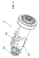
- the sprayhead 2 comprises a central nozzle 44 to distribute a central flow and acts with a plurality of peripheral nozzles for a peripheral rain spray effect.
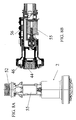
- the sprayhead 2 incorporates an electrovalve 55 positioned to deviate the water flow alternatively towards the central nozzle 44, or towards the peripheral nozzle 46, and an electric control 48 that is activated by the user, also mounted on the faucet to operate the electrovalve 55.
- the electric control 48 preferably comprises a button to operate the opening or closing action of the fluid flow.
- the electrovalve 55 mounted on the sprayhead 2 is therefore destined to change over the water flow distribution from the central jet 44 to the peripheral nozzles 46 by activating the press-button described above.
- the sprayhead 2 also comprises an electronic card 56 to contain further electrical commands for driving the motorised means on the regulation unit 1 by means of the electronic control and command unit 35, as schematically shown in figures 6 , 7 , 8A and 8B .
- the electrical control 48 can be included in the electronic card 56, or can be connected directly to the electrovalve 55 in order to permit separate operation of any further controls foreseen on the sprayhead 2, which will be described further on.
- the button 48 could also be the only button present on the sprayhead 2, and the electrovalve 55 could simply require only basic electrical supply to operate.
- a second electric control 38 and a third electric control 28 are mounted on the sprayhead 2 to regulate the flow rate and the fluid temperature, respectively.
- the second control 38 and the third control 28 are coupled with the motorised means 23, 24, which operate the valves 9 and 10 to regulate the closing and opening action of unit 1.
- the third electric control 28 for temperature regulation, and the second electric control 38 for flow rate regulation comprise respective increase and reduction buttons for temperature and flow rate, respectively.
- the second electric control 38 and the third electric control 28 are connected to the electronic command and control unit 35, through electric connection means 39 that follow the line of the flexible hose 27,contained inside a protection sheath 32 of said flexible hose.
- Figure 9 shows a schematic view of the structure of the electrical connections and interconnections between the electronic unit 35 and the components of unit 1 that regulates the fluid conveyance and distribution.
- the electronic unit 35 is advantageously housed in a hermetically waterproof portion 37 of a protection sheath 26 of the regulation unit 1, as shown in figures 3 to 5 .
- the sheath 26 is made from a transparent synthetic plastic material to permit rapid viewing and inspection of the regulation unit 1 components during maintenance operations.
- Respective electrical connections 41, 42 are foreseen between the unit 35 and each of the small electric motors 23, 24, as well as between the unit 35 and each of the press buttons 28, 38, and 48 on the sprayhead 2. These latter connections are shown schematically in figures 1 and 9 by means of a single connection 39.
- buttons 28, 38 can be electrically coupled with the electronic unit 35 by means of a wireless type connection.
- the sprayhead can be equipped with a signal transmitter device in radio frequency, while the unit 35 can contain a receiver for said signals in radio frequency.
- the electronic unit 35 comprises a control unit 40 that is supplied by an external transformer 36 by means of a voltage regulator 43.
- the electronic unit 35 is housed on a support card contained in the portion 37 of sheath 26.
- An external removable battery 47 is also foreseen to maintain the electronic unit 35 running in case of power failure.
- a circuit portion 49 is foreseen on the unit 35 card to regulate the power supply from battery 47.
- the control unit 40 can be an integrated circuit microcontroller comprising a plurality of control outlets to enable the respective outlet stages 57, 58, of jumper or semi-jumper power transistor to control the small electric motors 23, 24 of the opening and closing regulation valves 9 and 10.
- An interface 53 in bi-directional connection with the control unit 40 and with the commands 28 and 38 of the sprayhead is also foreseen, by means of the connection 39.
- a commonly known mechanical structure can also be maintained in the sprayhead, able to switch over the water flow from the central jet from the centre nozzle 44 which delivers the flow in a peripheral rain spray delivery through the nozzles 46 arranged in a circle around the centre nozzle.
- the regulation unit 1 also comprises a second safety electrovalve 50, in the monoblock 3, provided for opening or closing the fluid conveyance.
- the second safety electrovalve 50 is automatically operated in a closed position when there is no power supply, in order to shut off the water flow towards the sprayhead 2 when the electrical controls that drive the motorised means are not active, such as during an unexpected power failure or some fault in faucet function.
- the second electrovalve can also be activated manually by means of a press button 59, which can be positioned on the monoblock 3 for example, in order to cut off the fluid conveyance as required by the user.
- the electronic unit 35 comprises a further outlet stage 51, of the open collector type for example, able to operate the elctrovalve 50 in outlet.
- the user is able to switch over the fluid delivery from the centre nozzle to the peripheral nozzles, and vice versa, by closing the electrovalve 55.
- the sprayhead can be activated immediately by the user because head is destined per se to be gripped by the user for water flow delivery.
- the invention makes the presence of a mechanical control lever associated with the sprayhead support faucet, totally superfluous.
- the water flow control and regulation is simple and efficient in that the gripping of the sprayhead 2 is the only manual action required for fluid flow delivery.
Landscapes
- Domestic Plumbing Installations (AREA)
Priority Applications (2)
| Application Number | Priority Date | Filing Date | Title |
|---|---|---|---|
| EP07008958A EP1987884A1 (de) | 2007-05-03 | 2007-05-03 | Verbesserter Duschsprühkopf |
| PCT/EP2008/003376 WO2008135184A1 (en) | 2007-05-03 | 2008-04-25 | Improved showerhead |
Applications Claiming Priority (1)
| Application Number | Priority Date | Filing Date | Title |
|---|---|---|---|
| EP07008958A EP1987884A1 (de) | 2007-05-03 | 2007-05-03 | Verbesserter Duschsprühkopf |
Publications (1)
| Publication Number | Publication Date |
|---|---|
| EP1987884A1 true EP1987884A1 (de) | 2008-11-05 |
Family
ID=38477389
Family Applications (1)
| Application Number | Title | Priority Date | Filing Date |
|---|---|---|---|
| EP07008958A Withdrawn EP1987884A1 (de) | 2007-05-03 | 2007-05-03 | Verbesserter Duschsprühkopf |
Country Status (2)
| Country | Link |
|---|---|
| EP (1) | EP1987884A1 (de) |
| WO (1) | WO2008135184A1 (de) |
Cited By (1)
| Publication number | Priority date | Publication date | Assignee | Title |
|---|---|---|---|---|
| CN103316795A (zh) * | 2013-07-15 | 2013-09-25 | 朱红兵 | 防水调温喷头 |
Citations (5)
| Publication number | Priority date | Publication date | Assignee | Title |
|---|---|---|---|---|
| DE8806867U1 (de) * | 1987-06-06 | 1988-07-21 | A. u. K. Müller GmbH & Co KG, 4000 Düsseldorf | Elektromagnetisch betätigbares 5/2-Wegeventil |
| US4826129A (en) * | 1988-05-03 | 1989-05-02 | Caprilion Enterprise Company | Structure of faucet for automatic water supply and stoppage |
| EP0499151A2 (de) * | 1991-02-12 | 1992-08-19 | Toto Ltd. | Wasserspender mit einem durch einen kleinen Motor angetriebenen rotierenden Kopf |
| EP1132141A2 (de) * | 2000-03-10 | 2001-09-12 | Amfag S.p.a. | Herausziehbarer Brausekopf für die Küche |
| US20070018019A1 (en) * | 2005-07-21 | 2007-01-25 | Fabrizio Nobili | Spray head for differential delivery of treated water and mains water |
-
2007
- 2007-05-03 EP EP07008958A patent/EP1987884A1/de not_active Withdrawn
-
2008
- 2008-04-25 WO PCT/EP2008/003376 patent/WO2008135184A1/en not_active Ceased
Patent Citations (5)
| Publication number | Priority date | Publication date | Assignee | Title |
|---|---|---|---|---|
| DE8806867U1 (de) * | 1987-06-06 | 1988-07-21 | A. u. K. Müller GmbH & Co KG, 4000 Düsseldorf | Elektromagnetisch betätigbares 5/2-Wegeventil |
| US4826129A (en) * | 1988-05-03 | 1989-05-02 | Caprilion Enterprise Company | Structure of faucet for automatic water supply and stoppage |
| EP0499151A2 (de) * | 1991-02-12 | 1992-08-19 | Toto Ltd. | Wasserspender mit einem durch einen kleinen Motor angetriebenen rotierenden Kopf |
| EP1132141A2 (de) * | 2000-03-10 | 2001-09-12 | Amfag S.p.a. | Herausziehbarer Brausekopf für die Küche |
| US20070018019A1 (en) * | 2005-07-21 | 2007-01-25 | Fabrizio Nobili | Spray head for differential delivery of treated water and mains water |
Cited By (1)
| Publication number | Priority date | Publication date | Assignee | Title |
|---|---|---|---|---|
| CN103316795A (zh) * | 2013-07-15 | 2013-09-25 | 朱红兵 | 防水调温喷头 |
Also Published As
| Publication number | Publication date |
|---|---|
| WO2008135184A1 (en) | 2008-11-13 |
Similar Documents
| Publication | Publication Date | Title |
|---|---|---|
| US5226629A (en) | Remote controlled faucet | |
| EP3649298B1 (de) | Integrierte leitungswasser- und konditionierte wasserhahnanordnung mit ausziehbarem sprühkopf | |
| CA2925608C (en) | Faucet-integrated touch-free soap dispensing systems | |
| CA2474178A1 (en) | Sink side touchless foam dispenser | |
| EP0195271A2 (de) | Wasserversorgungsinstallation für Waschzwecke | |
| US20180244541A1 (en) | Water faucet having a capsule-based filter | |
| US20080006707A1 (en) | Showerhead with simplified actuator | |
| US20240083771A1 (en) | Faucet with Integrated Enhanced Water Stream | |
| EP2065520A1 (de) | Système mitigeur | |
| WO2008135184A1 (en) | Improved showerhead | |
| EP1953506A1 (de) | Elektronisches Steuersystem für die Flüssigkeitsversorgung von Spülbecken, Badewannen, Duschen und dergleichen | |
| CN219732173U (zh) | 淋浴器 | |
| EP1876304A1 (de) | Duschkopf mit vereinfachtem Betätiger | |
| KR20190067518A (ko) | 안마장치와 블루투스 장치를 겸비한 원격제어 샤워 시스템 | |
| CN213929543U (zh) | 一种多功能感应出水装置 | |
| US20110253241A1 (en) | Water-Saving Faucet Whose Water Output is Controlled By A Preset Temperature | |
| JP2007524796A (ja) | 節水バルブシステム | |
| CN114767305A (zh) | 出水装置 | |
| JP7122572B2 (ja) | トイレ用手洗い器システム | |
| JPH01158128A (ja) | 混合装置 | |
| CN209107117U (zh) | 一种多功能淋浴器 | |
| EP0894903B2 (de) | Kalt-/Warmwasser-Mischbatterie für Waschtische, Wasch- und Spülbecken, Handwaschbecken, Duschen, Wannen u. dgl. | |
| RU209133U1 (ru) | Устройство контроля подачи воды | |
| KR200344204Y1 (ko) | 세척액의 자동공급을 위한 수전금구 구조 | |
| JPH11303161A (ja) | 水栓設置用アダプター |
Legal Events
| Date | Code | Title | Description |
|---|---|---|---|
| PUAI | Public reference made under article 153(3) epc to a published international application that has entered the european phase |
Free format text: ORIGINAL CODE: 0009012 |
|
| AK | Designated contracting states |
Kind code of ref document: A1 Designated state(s): AT BE BG CH CY CZ DE DK EE ES FI FR GB GR HU IE IS IT LI LT LU LV MC MT NL PL PT RO SE SI SK TR |
|
| AX | Request for extension of the european patent |
Extension state: AL BA HR MK RS |
|
| 17P | Request for examination filed |
Effective date: 20090401 |
|
| 17Q | First examination report despatched |
Effective date: 20090518 |
|
| AKX | Designation fees paid |
Designated state(s): AT BE BG CH CY CZ DE DK EE ES FI FR GB GR HU IE IS IT LI LT LU LV MC MT NL PL PT RO SE SI SK TR |
|
| STAA | Information on the status of an ep patent application or granted ep patent |
Free format text: STATUS: THE APPLICATION IS DEEMED TO BE WITHDRAWN |
|
| 18D | Application deemed to be withdrawn |
Effective date: 20091201 |