EP1987991B1 - Pneumatische sicherheitsgurtvorrichtung für fahrzeug - Google Patents
Pneumatische sicherheitsgurtvorrichtung für fahrzeug Download PDFInfo
- Publication number
- EP1987991B1 EP1987991B1 EP07708058A EP07708058A EP1987991B1 EP 1987991 B1 EP1987991 B1 EP 1987991B1 EP 07708058 A EP07708058 A EP 07708058A EP 07708058 A EP07708058 A EP 07708058A EP 1987991 B1 EP1987991 B1 EP 1987991B1
- Authority
- EP
- European Patent Office
- Prior art keywords
- inflation
- time
- vehicle
- guide
- occupant
- Prior art date
- Legal status (The legal status is an assumption and is not a legal conclusion. Google has not performed a legal analysis and makes no representation as to the accuracy of the status listed.)
- Not-in-force
Links
- 230000000452 restraining effect Effects 0.000 claims abstract description 5
- 238000004804 winding Methods 0.000 claims description 35
- 230000000694 effects Effects 0.000 claims description 9
- 210000000115 thoracic cavity Anatomy 0.000 claims description 4
- 230000002123 temporal effect Effects 0.000 abstract 2
- 230000001105 regulatory effect Effects 0.000 description 45
- 238000013459 approach Methods 0.000 description 3
- 210000000038 chest Anatomy 0.000 description 2
Images


Classifications
-
- B—PERFORMING OPERATIONS; TRANSPORTING
- B60—VEHICLES IN GENERAL
- B60R—VEHICLES, VEHICLE FITTINGS, OR VEHICLE PARTS, NOT OTHERWISE PROVIDED FOR
- B60R22/00—Safety belts or body harnesses in vehicles
- B60R22/28—Safety belts or body harnesses in vehicles incorporating energy-absorbing devices
-
- B—PERFORMING OPERATIONS; TRANSPORTING
- B60—VEHICLES IN GENERAL
- B60R—VEHICLES, VEHICLE FITTINGS, OR VEHICLE PARTS, NOT OTHERWISE PROVIDED FOR
- B60R21/00—Arrangements or fittings on vehicles for protecting or preventing injuries to occupants or pedestrians in case of accidents or other traffic risks
- B60R21/02—Occupant safety arrangements or fittings, e.g. crash pads
- B60R21/16—Inflatable occupant restraints or confinements designed to inflate upon impact or impending impact, e.g. air bags
- B60R21/18—Inflatable occupant restraints or confinements designed to inflate upon impact or impending impact, e.g. air bags the inflatable member formed as a belt or harness or combined with a belt or harness arrangement
-
- B—PERFORMING OPERATIONS; TRANSPORTING
- B60—VEHICLES IN GENERAL
- B60R—VEHICLES, VEHICLE FITTINGS, OR VEHICLE PARTS, NOT OTHERWISE PROVIDED FOR
- B60R22/00—Safety belts or body harnesses in vehicles
- B60R22/02—Semi-passive restraint systems, e.g. systems applied or removed automatically but not both ; Manual restraint systems
- B60R22/023—Three-point seat belt systems comprising two side lower and one side upper anchoring devices
-
- B—PERFORMING OPERATIONS; TRANSPORTING
- B60—VEHICLES IN GENERAL
- B60R—VEHICLES, VEHICLE FITTINGS, OR VEHICLE PARTS, NOT OTHERWISE PROVIDED FOR
- B60R22/00—Safety belts or body harnesses in vehicles
- B60R22/12—Construction of belts or harnesses
- B60R22/14—Construction of belts or harnesses incorporating enlarged restraint areas, e.g. vests, nets, crash pads, optionally for children
-
- B—PERFORMING OPERATIONS; TRANSPORTING
- B60—VEHICLES IN GENERAL
- B60R—VEHICLES, VEHICLE FITTINGS, OR VEHICLE PARTS, NOT OTHERWISE PROVIDED FOR
- B60R22/00—Safety belts or body harnesses in vehicles
- B60R22/18—Anchoring devices
- B60R22/24—Anchoring devices secured to the side, door, or roof of the vehicle
-
- B—PERFORMING OPERATIONS; TRANSPORTING
- B60—VEHICLES IN GENERAL
- B60R—VEHICLES, VEHICLE FITTINGS, OR VEHICLE PARTS, NOT OTHERWISE PROVIDED FOR
- B60R21/00—Arrangements or fittings on vehicles for protecting or preventing injuries to occupants or pedestrians in case of accidents or other traffic risks
- B60R2021/003—Arrangements or fittings on vehicles for protecting or preventing injuries to occupants or pedestrians in case of accidents or other traffic risks characterised by occupant or pedestian
- B60R2021/0039—Body parts of the occupant or pedestrian affected by the accident
- B60R2021/0044—Chest
-
- B—PERFORMING OPERATIONS; TRANSPORTING
- B60—VEHICLES IN GENERAL
- B60R—VEHICLES, VEHICLE FITTINGS, OR VEHICLE PARTS, NOT OTHERWISE PROVIDED FOR
- B60R21/00—Arrangements or fittings on vehicles for protecting or preventing injuries to occupants or pedestrians in case of accidents or other traffic risks
- B60R2021/003—Arrangements or fittings on vehicles for protecting or preventing injuries to occupants or pedestrians in case of accidents or other traffic risks characterised by occupant or pedestian
- B60R2021/0039—Body parts of the occupant or pedestrian affected by the accident
- B60R2021/0048—Head
-
- B—PERFORMING OPERATIONS; TRANSPORTING
- B60—VEHICLES IN GENERAL
- B60R—VEHICLES, VEHICLE FITTINGS, OR VEHICLE PARTS, NOT OTHERWISE PROVIDED FOR
- B60R21/00—Arrangements or fittings on vehicles for protecting or preventing injuries to occupants or pedestrians in case of accidents or other traffic risks
- B60R21/01—Electrical circuits for triggering passive safety arrangements, e.g. airbags, safety belt tighteners, in case of vehicle accidents or impending vehicle accidents
- B60R2021/01204—Actuation parameters of safety arrangents
- B60R2021/01252—Devices other than bags
- B60R2021/01265—Seat belts
Definitions
- the present invention relates to an airbelt apparatus for a vehicle, which includes an inflation portion that corresponds with a cephalic region of an occupant at a time of inflation.
- a vehicle airbelt apparatus has been disclosed ( JP 2002-527282A ) in which an occupant restraint webbing with an inflation portion passes through a belt guide disposed at a shoulder portion of a seatback, and the inflation portion can be inflated by an inflator fixed to a seatback frame.
- US 5,829,841 A discloses an inflatable seat belt tensioner which is intended to provide an occupant side head protection.
- a belt guide mounted on the seat back headrest guides movement of the seat belt during operation between a clamping member and a clamping surface. When sudden vehicle deceleration is sensed, an inflator mounted in the headrest simultaneously moves the clamping member to clamp the belt to the clamping surface against movement and inflates the bag.
- DE 199 50 951 A1 which comprises the features mentioned in the preamble of claim 1, discloses an air belt apparatus which comprised guiding means for an inflatable seat belt which is provided at a belt return which is capable of changing its cross-sectional shape upon inflation of the seat belt so as to allow the seat belt to inflate beyond this belt return and to provide always the same volume of the air belt irrespective of whether the occupant is tall or small.
- the inflation portion is pressed against the occupant by tension of the occupant restraint webbing, which increases when the inflation portion inflates.
- the inflation portion is regulated by the belt guide, which is formed to be horizontally long to match the occupant restraint webbing, and the inflation portion inflates to broaden in a horizontal direction, which is to say a vehicle lateral direction.
- the inflation portion it has been difficult for the inflation portion to be inflated to an upward position corresponding to a temple area of the occupant, as a response to a side impact.
- the invention is an apparatus according to claim 1.
- the inflator when a side impact toward a side of the occupant is detected or predicted by the side impact sensor, the inflator operates, a large quantity of gas is ejected from the inflator, and the inflation portion is inflated by the gas.
- the cross-sectional shape of the inflation portion is regulated, by restraining inflation of the inflation portion to the vehicle lateral direction outer side with the inflation-time cross-sectional shape regulation component, so as to be an oblong shape which is long in the vertical direction at the shoulder portion of the seatback, and the inflation portion inflates to sideward of the cephalic region of the occupant. Consequently, at the time of a side impact, it is possible to inflate the inflation portion to an upward position corresponding with a temple area of an occupant.
- the invention of claim 2 is the airbelt apparatus for a vehicle of claim 1 wherein the inflation-time cross-sectional shape regulation component is an inflation-time regulation belt guide at which an inflation-time regulation guide hole is provided, the guide hole having a elliptical shape that is longer in the vertical direction than in a vehicle lateral direction, so as to regulate the cross-sectional shape of the inflation portion at the time of inflation, and an upper end of the inflation-time regulation guide hole being provided so as to extend to a position sideward of a headrest of even height therewith.
- the inflation-time cross-sectional shape regulation component is an inflation-time regulation belt guide at which an inflation-time regulation guide hole is provided, the guide hole having a elliptical shape that is longer in the vertical direction than in a vehicle lateral direction, so as to regulate the cross-sectional shape of the inflation portion at the time of inflation, and an upper end of the inflation-time regulation guide hole being provided so as to extend to a position sideward of a headrest of even height therewith.
- the inflation-time regulation guide hole of the inflation-time regulation belt guide is formed with the substantially elliptical form which is longer in the vertical direction than in the vehicle lateral direction.
- the cross-sectional shape of the inflation portion is regulated by the inflation-time regulation guide hole so as to have the oblong shape which is long in the vertical direction.
- the upper end of the inflation-time regulation guide hole is extended up to the position sideward of the headrest of even height therewith.
- the inflation portion can be inflated up to the height position sideward of the headrest. Accordingly, by the inflation portion being inflated to be oblong up to the height position sideward of the headrest, the inflation portion can be caused to inflate up to a height position corresponding with the temple area of an occupant.
- the invention of claim 3 is the airbelt apparatus for a vehicle of claim 2 wherein a normal-time regulation belt guide that is disposed in a region within the inflation-time regulation guide hole, and at which a normal-time regulation guide hole is provided which regulates a winding direction of the occupant restraint webbing passing therethrough at times of normal use, and that is expanded by inflation of the inflation portion.
- the winding direction of the occupant restraint webbing is regulated by the normal-time regulation belt guide.
- the normal-time regulation belt guide is deployed by the inflation, and thus the cross-sectional shape of the inflation portion is regulated by the inflation-time regulation belt guide so as to be the oblong shape which is long in the vertical direction.
- the winding direction of the occupant restraint webbing can be regulated by the normal-time regulation belt guide at times of normal use, in addition to which it is possible to improve protection characteristics of the cephalic region of an occupant at the time of a side impact.
- the invention of claim 4 is the airbelt apparatus for a vehicle of claim 1 wherein the inflation-time cross-sectional shape regulation component is a belt guide that is configured to be accommodated in the seatback at times of normal use and at which a normal-time regulation guide hole is formed that is configured to regulate a winding direction of the occupant restraint webbing passing therethrough between an upper end portion thereof and an upper edge portion of the shoulder portion in an accommodated state.
- the inflation-time cross-sectional shape regulation component is a belt guide that is configured to be accommodated in the seatback at times of normal use and at which a normal-time regulation guide hole is formed that is configured to regulate a winding direction of the occupant restraint webbing passing therethrough between an upper end portion thereof and an upper edge portion of the shoulder portion in an accommodated state.
- the belt guide is accommodated in the seatback and the winding direction of the occupant restraint webbing is regulated by the normal-time regulation guide hole, which is formed between the upper end portion thereof and the upper edge portion of the seatback shoulder portion.
- the inflation portion is inflated, the belt guide protrudes upward from the seatback shoulder portion and goes into a non-accommodated state, due to the inflation, and the guide hole broadens upward and becomes the inflation-time regulation guide hole.
- the cross-sectional shape of the inflation portion is regulated by this inflation-time regulation guide hole so as to be in the oblong shape which is long in the vertical direction at the seatback shoulder portion, and the inflation portion inflates to sideward of the cephalic region of the occupant.
- the winding direction of the occupant restraint webbing can be regulated by the normal-time regulation belt guide at times of normal use, in addition to which it is possible to improve protection characteristics of the cephalic region of an occupant at the time of a side impact.
- the invention of claim 5 is the airbelt apparatus for a vehicle of claim 1 wherein the inflation-time cross-sectional shape regulation component is a pair of guide half-pieces that are respectively supported at support points provided at an interval in a vehicle lateral direction, that are configured to overlap each other and to expand in opposite directions from each other about the support points.
- the inflation-time cross-sectional shape regulation component is a pair of guide half-pieces that are respectively supported at support points provided at an interval in a vehicle lateral direction, that are configured to overlap each other and to expand in opposite directions from each other about the support points.
- the cross-sectional shape of the inflation portion is regulated by the guide hole that has broadened upward so as to be in the oblong shape which is long in the vertical direction at the seatback shoulder portion, and the inflation portion inflates to sideward of the cephalic region of the occupant.
- the winding direction of the occupant restraint webbing can be regulated by the pair of guide half-pieces in the overlapped state at times of normal use, in addition to which it is possible to improve protection characteristics of the cephalic region of an occupant at the time of a side impact.
- the invention of claim 6 is the airbelt apparatus for a vehicle of claim 1 wherein the inflation-time cross-sectional shape regulation component is a belt guide that elastically deforms, or turns about a support point provided at the shoulder portion, due to inflation of the inflation portion, and that is configured to expand within a predetermined range in a direction away from the cephalic region of the occupant.
- the inflation-time cross-sectional shape regulation component is a belt guide that elastically deforms, or turns about a support point provided at the shoulder portion, due to inflation of the inflation portion, and that is configured to expand within a predetermined range in a direction away from the cephalic region of the occupant.
- the winding direction of the occupant restraint webbing is regulated at times of normal use by the non-deployed belt guide.
- the belt guide is elastically deformed by this inflation or turns about the support point provided at the seatback shoulder portion, and deploys within the predetermined range in the direction away from the cephalic region of the occupant.
- a guide surface which regulates the cross-sectional shape of the inflation portion to the oblong shape which is long in the vertical direction, is formed at the belt guide.
- the cross-sectional form of the inflation portion is regulated by the guide surface of the belt guide and forms the oblong shape which is long in the vertical direction at the seatback shoulder portion.
- the inflation portion inflates to sideward of the cephalic region of an occupant. Consequently, it is possible to improve protection characteristics of the cephalic region of the occupant at the time of a side impact.
- the invention of claim 7 is the airbelt apparatus for a vehicle of any one of claims 1 to 6 wherein the shoulder portion of the seatback, at which the inflation-time cross-sectional shape regulation component is provided, forms an inclined surface at which a distance from a vehicle lateral direction middle portion of the vehicle seat to an upper portion of the shoulder portion is smaller than the distance to a lower portion of the shoulder portion.
- the seatback shoulder portion forms an outward-curving inclined surface.
- the inflation portion is drawn in toward the middle portion of the vehicle seat by an increase in tension of the occupant restraint webbing, in accordance with which the inflation portion rises up the inclined surface, and resultantly the inflation portion moves upward.
- the inflation portion can bodily approach the head portion of the occupant.
- the inflation portion can be inflated to an upward position corresponding with a temple area of an occupant at the time of a side impact.
- an excellent effect is provided in that the inflation portion is inflated to be oblong up to a height position sideward of the headrest, and thus the inflation portion can be inflated up to a height position corresponding with a temple area of an occupant.
- an excellent effect is provided in that the winding direction of the occupant restraint webbing can be regulated by the normal-time regulation belt guide at times of normal use and in that protection characteristics of the cephalic region of an occupant at the time of a side impact can be further improved.
- an excellent effect is provided in that the winding direction of the occupant restraint webbing can be regulated by the normal-time regulation guide hole of the accommodated belt guide at times of normal use and in that the cross-sectional shape of the inflation portion is regulated by the guide hole of the guide belt broadening upward at the time of a side impact and protection characteristics of the cephalic region of an occupant can be further improved.
- an excellent effect is provided in that the winding direction of the occupant restraint webbing can be regulated by the pair of guide half-pieces in the overlapped state at times of normal use and in that the pair of guide half-pieces are deployed at the time of a side impact, the cross-sectional shape of the inflation portion is regulated and protection characteristics of the cephalic region of an occupant can be further improved.
- an excellent effect is provided in that the cross-sectional form of the inflation portion is regulated by a guide surface of the belt guide and the inflation portion is inflated to sideward of the cephalic region of an occupant, and thus protection characteristics of the cephalic region of an occupant at the time of a side impact can be further improved.
- an excellent effect is provided in that the inflation portion can bodily approach the head portion of the occupant at the time of a side impact.
- a vehicle airbelt apparatus 10 relating to the present exemplary embodiment is a type of seat belt for restraining an occupant 14 who is sitting at a vehicle seat 12, and has: an occupant restraint webbing 16, an inflation portion 18, an inflator (not shown), a side impact sensor (not shown), a control unit (not shown), a first belt guide 21, which is an example of a normal-time regulation belt guide, and a second belt guide 22, which is an example of an inflation-time cross-sectional shape regulation component.
- the vehicle seat 12 has a seat cushion (not shown) at which the occupant 14 sits, a seatback 26 which supports the back of the occupant 14, and a headrest 28 which is provided at the seatback 26 and corresponds with a cephalic region 14H of the occupant 14.
- a lapbelt anchor is provided at a vehicle cabin outer side side portion of the seat cushion, and an unillustrated buckle apparatus is provided at a vehicle cabin middle side side portion of the seat cushion.
- positions of provision of the lapbelt anchor and the buckle apparatus are not limited to the seat cushion and may be, for example, at a floor panel side.
- a gas supply source for the inflation portion 18, for example, an inflator is disposed inside the buckle apparatus or at an exterior portion of the buckle apparatus (not shown).
- the control unit operates the inflator when a side impact is detected by the side impact sensor or a side impact is predicted by an unillustrated pre-crash sensor.
- the inflator is also operated when a front impact is detected or predicted.
- a front impact inflator and a side impact inflator may be separately utilized, or this may correspond to a single inflator whose output is variable.
- the occupant restraint webbing 16 is a belt corresponding with the chest portion 14B of the occupant 14, and is configured to be windable onto a retractor (not shown) which is disposed, for example, at an upper back panel of the vehicle.
- a retractor not shown
- the occupant restraint webbing 16 can be drawn out from the retractor to fit the physique of the occupant 14.
- the occupant restraint webbing 16 is guided by the first belt guide 21 such that a winding direction thereof is regulated.
- a tongue plate (not shown), which is configured to be fittable into the buckle apparatus, is provided at the occupant restraint webbing 16.
- gas from the inflator can be supplied to the inflation portion 18 from the buckle apparatus side.
- the inflation portion 18 is a bag which is provided at the occupant restraint webbing 16 and is folded up so as to correspond with the cephalic region 14H of the occupant 14 at a time of inflation. Specifically, the inflation portion 18 is folded up into a belt form similar to the occupant restraint webbing 16 and is covered with, for example, a mesh webbing with extensibility (not shown) and further covered with a cover (not shown). The inflation portion 18 is stitched into the belt form using control stitching, known as a tear seam, that ruptures when an internal pressure in the inflation portion 18 is at or above a certain value. A region of deployment of the inflation portion 18 is not limited to positions corresponding with the cephalic region 14H of the occupant 14; it may inflate to correspond as far as the chest portion 14B.
- the first belt guide 21 is disposed at a region within an inflation-time regulation guide hole 22A of the second belt guide 22, which will be described below.
- the first belt guide 21 is provided with a normal-time regulation guide hole 21 A which regulates the winding direction of the occupant restraint webbing 16 passing therethrough at times of normal use.
- the first belt guide 21 is structured so as to deploy with inflation of the inflation portion 18.
- the first belt guide 21 is a flexible member provided at a shoulder portion of the seatback 26 in a region that is within the inflation-time regulation guide hole 22A of the second belt guide 22 in a front view of the vehicle.
- the normal-time regulation guide hole 21 A is formed to be wide in a lateral direction of the occupant restraint webbing 16 and short in a thickness direction of the occupant restraint webbing 16, for guiding at times of normal use.
- a bottom portion 21 B which extends in the lateral direction of the occupant restraint webbing 16 is fixed to the shoulder portion of the seatback 26 using stitching, clips or the like.
- Upper pieces 21C and 21D are provided extending from two length direction ends of the bottom portion 21 B. In a state in which the upper pieces 21C and 21D are folded over and formed into a flat loop shape with end portions thereof overlapping, the end portions are fastened together by, for example, a button 32.
- the normal-time regulation guide hole 21 A is formed which is long in the lateral direction and short in the thickness direction of the occupant restraint webbing 16.
- components for fastening the upper pieces 21C and 21D are not limited to the button 32 and any components may be used as long as it is a structure with which the upper pieces 21C and 21 D can be separated from one another by inflation force of the inflation portion 18 and the first belt guide 21 can deploy, such as a hook, a surface fastener, stitching with a tear seam, or the like.
- the first belt guide 21 may be formed in a loop form without a seam, at which a rupture preparation portion is provided in an upper piece, and the first belt guide 21 may be deployed by the rupture preparation portion rupturing due to inflation force when the inflation portion 18 is inflated.
- the second belt guide 22 is provided at the shoulder portion of the seatback 26 of the vehicle seat 12, and the occupant restraint webbing 16 passes therethrough.
- the second belt guide 22 is an inflation-time regulation belt guide which regulates a cross-sectional shape of the inflation portion 18, at a time of inflation of the inflation portion 18, so as to be an oblong shape which is long in the vertical direction.
- the second belt guide 22 is longer in the vertical direction than the vehicle lateral direction, and is provided with the inflation-time regulation guide hole 22A having a substantially elliptical shape in which an upper end 22B is provided extending as far as a height position sideward of the headrest 28.
- the second belt guide 22 extends from an end portion 22C, which is fixed at the seat middle side relative to the first belt guide 21 of the seatback 26, to an end portion 22D, which is fixed at a position beyond the first belt guide 21. As shown in Fig. 1 , the second belt guide 22 extends upward and to the vehicle lateral direction outer side from the end portion 22C to the upper end 22B of the inflation-time regulation guide hole 22A, extends downward and to the vehicle lateral direction outer side from the upper end 22B to an outer end 22E, and extends downward and toward the seat middle from the outer end 22E to the end portion 22D.
- a position of the outer end 22E does not project much to the vehicle lateral direction outer side and is, for example, disposed at the seat middle side relative to a maximum width position of the seatback 26.
- the second belt guide 22 forms an arch shape protruding diagonally upward from the shoulder portion of the seatback 26, and at times of normal, use, can also be used as a handle when operating the seatback 26.
- the shape of the second belt guide 22 is not limited to the illustrated shape, and may be any shape which can regulate the cross-sectional shape of the inflation portion 18 to an oblong shape which is long in the vertical direction at a time of inflation: Further, in a case in which the second belt guide 22 can regulate winding of the occupant restraint webbing 16 at times of normal use and can also perform the function of the first belt guide 21, the first belt guide 21 need not be provided.
- the winding direction of the occupant restraint webbing 16 is regulated by the first belt guide 21, and the occupant restraint webbing 16 can be guided by the first belt guide 21.
- the second belt guide 22 is usable as a handle portion at times of mounting/dismounting, times of operation of the seatback 26 and the like.
- the inflator In a state in which the occupant restraint webbing 16 is applied, if a side impact is received from the side of the vehicle at which the occupant is sitting or such an impact is predicted, the inflator operates and, as shown in Fig. 3 , the inflation portion 18 inflates. At this time, the button 32 of the first belt guide 21 is disengaged by inflation force of the inflation portion 18, and the upper pieces 21C and 21D move away from each other and deploy.
- an inflated shape of the inflation portion 18 is regulated by the inflation-time regulation guide hole 22A of the second belt guide 22 and, at the position of the second belt guide 22, the cross-sectional shape of the inflation portion 18 forms an oblong shape which is long in the vertical direction up to a height position sideward of the headrest 28.
- the winding direction of the occupant restraint webbing 16 is regulated by the first belt guide 21 at times of normal use, in addition to which, at the time of a side impact, the inflated shape of the inflation portion 18 is regulated by the second belt guide 22 and the inflation portion 18 can be inflated up to a height position corresponding with a temple area 14S of the occupant 14.
- inertial force of the cephalic region 14H of the occupant 14 in the vehicle lateral direction can be absorbed by the inflation portion 18.
- the inflation portion 18 is inflated to be oblong at a position corresponding with the temple area 14S, a broad region, for example, from a neck area 14N to the cephalic region 14H can be protected, and thus cephalic region protection characteristics are more excellent.
- a vehicle airbelt apparatus 20 relating to the present exemplary embodiment is provided with a belt guide 24 which serves as an inflation-time cross-sectional shape regulation component.
- the belt guide 24 has a pair of guide half-pieces 44 and 46, which are pivoted respectively at a support point 34 provided at an interval in the vehicle lateral direction, are configured to overlap each other, and can be expanded in opposite directions from each other about the support points 34 and 36.
- the guide half-piece 44 is pivoted at the support point 34, at the seat middle side, and the guide half-piece 46 is pivoted at the support point 36, at the vehicle lateral direction outer side relative to the support point 34.
- the pair of guide half-pieces 44 and 46 are, for example, respectively formed in circular arc shapes in a front view of the vehicle, and the guide half-piece 46 is formed with a slightly larger radius of curvature than the guide half-piece 44 such that the guide half-piece 46 can be overlapped onto the guide half-piece 44. Further, the guide half-piece 44 is formed with, for example, a "U"-shaped cross-section which opens upward, such that the guide half-piece 46 can be overlapped by being fitted into the opening portion.
- the headrest 28 is formed integrally with the seatback 26, and the pair of guide half-pieces 44 and 46 are formed at an inclined surface 42 that extends from the headrest 28 to the shoulder portion of the seatback 26.
- a stopper 38 is provided at the shoulder portion of the seatback 26, which restricts further turning when the guide half-piece 46 has turned through a predetermined angle. The restricting of the range of turning of the guide half-piece 46 is for restraining inflation of the inflation portion 18 to the vehicle lateral direction outer side, and causing the inflation portion 18 to inflate further upward.
- a structure of the stopper 38 is not limited to the illustrated structure.
- a structure may be formed such that a protruding portion is provided at the guide half-piece 46 side, and the protruding portion abuts against the shoulder portion of the seatback 26 when the guide half-piece 46 has turned through the predetermined angle, and thus restricts further turning.
- distal ends 44A and 46A of the guide half-pieces 44 and 46 are structured so as to engage with one another when the belt guide 24 is deployed. Accordingly, at a time of inflation, an inflation-time regulation guide hole 52 is formed, which regulates the cross-sectional shape of the inflation portion 18.
- the engagement of the distal ends 44A and 46A may utilize any components as long as the form can withstand inflation force of the inflation portion 18.
- the guide half-pieces 44 and 46 in an overlapped state.
- components are utilized that, for example, anchors the guide half-pieces 44 and 46 to a degree that will be disengaged by inflation force of the inflation portion 18, or that urges the guide half-pieces 44 and 46 in directions of overlap with a elastic body (not shown) that will be deformed by the inflation force.
- the components for maintaining the guide half-pieces 44 and 46 in the overlapped state are not limited to these.
- the guide half-piece 46 desirably has stiffness to a level that will not be deformed by the inflation force of the inflation portion 18.
- the guide half-piece 44 may have a lower stiffness than the guide half-piece 46, with a certain degree of deformation being allowed. If the guide half-piece 44 deforms, the inflation portion 18 can deploy upward by a corresponding amount, and cephalic region protection characteristics are consequently broadened.
- the seatback 26 and the headrest 28 are integrally formed, but this is not a limitation and, as in the first exemplary embodiment, the headrest 28 and the seatback 26 may be separate bodies.
- the guide half-pieces 44 and 46 are in the overlapped state at times of normal use but the guide half-pieces 44 and 46 may be, for example, disposed in a row one behind the other.
- the belt guide 24 has one pair of the guide half-pieces 44 and 46 but may have plural pairs of guide ico-pieces.
- a substantially semi-circular normal-time regulation guide hole 50 is formed at the belt guide 24.
- the winding direction of the occupant restraint webbing 16 can be regulated at times of normal use by the normal-time regulation guide hole 50. Consequently, a sense of application when the occupant 14 applies the occupant restraint webbing 16 is excellent.
- the inflator operates and, as shown in Fig. 6 , the inflation portion 18 inflates.
- the pair of guide half-pieces 44 and 46 turn in respectively opposite directions about the support points 34 and 36 and expand due to inflation force of the inflation portion 18.
- the guide half-piece 46 deploys until it abuts against the stopper 38, and the guide half-piece 44 deploys until the distal end 44A engages with the distal end 46A.
- the expansion of the belt guide 24 is ended by the distal ends 44A and 46A engaging with one another, and the cross-sectional shape of the inflation portion 18 is regulated by the inflation-time regulation guide hole 52 that is formed accordingly.
- Inflation of the inflation portion 18 to the vehicle lateral direction outer side is restrained by the range of turning of the guide half-piece 46 being restricted by the stopper 38.
- the guide half-piece 44 turns upward with the support point 34 serving as a support point, a region of the inflation-time regulation guide hole 52 that is close to the cephalic region 14H broadens upward.
- the inflation portion 18 While the inflation portion 18 approaches the temple area 14S along the shape of the inflation-time regulation guide hole 52 and is lifted up by the inclined surface 42, the inflation portion 18 inflates upward from the shoulder portion of the seatback 26, up to a height position corresponding with the temple area 14S.
- the winding direction of the occupant restraint webbing 16 can be regulated by the compactly overlapped guide half-pieces 44 and 46 at times of normal use.
- appearance is better.
- the guide half-pieces 44 and 46 that were overlapped at times of normal use deploy, the inflation portion 18 is caused to inflate up to a height position corresponding with the temple area 14S of the occupant 14 by the inflation-time regulation guide hole 52 that is accordingly formed, and a stable shape can be maintained within the inflation-time regulation guide hole 52.
- inertial force of the cephalic region 14H of the occupant 14 in the vehicle lateral direction is absorbed by the inflation portion 18 and, for example, from the neck area 14N up to the cephalic region 14H can be protected.
- a vehicle airbelt apparatus 30 relating to the present exemplary embodiment has, as the inflation-time cross-sectional shape regulation component, a belt guide 54 at the shoulder portion of the seatback 26, which elastically deforms due to inflation of the inflation portion 18 and can deploy within a predetermined range in the direction away from the cephalic region 14H of the occupant 14.
- the range of deployment of the belt guide 54 is restricted in order to restrain inflation of the inflation portion 18 to the vehicle lateral direction outer side and cause the inflation portion 18 to inflate further upward.
- an inclined surface 56 that is angled upward toward the seat middle is formed at the shoulder portion of the seatback 26.
- a root portion 54A of the belt guide 54 is supported at a lower portion of the inclined surface 56, and it extends diagonally upward to a distal end 54B in a cantilever state, substantially parallel with the inclined surface 56, with a length equal to, for example, a width dimension of the occupant restraint webbing 16.
- the occupant restraint webbing 16 passes through between the belt guide 54 and the inclined surface 56, and the winding direction is regulated.
- the distal end 54B of the belt guide 54 is separated from the inclined surface 56 to an extent such that the occupant restraint webbing 16 can be unhooked.
- the belt guide 54 may be capable of deploying in the direction away from the cephalic region 14H of the occupant 14 with inflation of the inflation portion 18, by turning about a support point (not shown) provided at the shoulder portion of the seatback 26.
- the winding direction of the occupant restraint webbing 16 can be regulated by the belt guide 54 in the state which is substantially parallel with the inclined surface 56, and a sense of application when the occupant 14 seated on the vehicle seat 12 has applied the occupant restraint webbing 16 is excellent.
- the inflator operates and, as shown in Fig. 8 , the inflation portion 18 inflates.
- the belt guide 54 elastically deforms due to inflation force of the inflation portion 18, and deploys in the direction away from the cephalic region 14H of the occupant 14.
- the belt guide 54 deploys to an extent of being, for example, substantially parallel with the vehicle vertical direction, and further deployment is restricted by an unillustrated stopper or the like.
- the inflation portion 18 acts to inflate toward the seat middle and upward along the belt guide 54. At this time, when the inflation portion 18 acts to inflate toward the seat middle, the inflation portion 18 is lifted up further by the inclined surface 56 provided at the seatback 26, and thus easily inflates to a height position corresponding with the temple area 14S of the occupant 14.
- inflation of the inflation portion 18 to the vehicle lateral direction outer side can be restrained by the belt guide 54, in addition to which the inflation portion 18 can be caused to inflate to the height position corresponding with the temple area 14S of the occupant 14, by utilizing the inclined surface 56 provided at the seatback 26.
- Inertial force of the cephalic region 14H of the occupant 14 in the vehicle lateral direction is absorbed by the inflation portion 18, and protection of the cephalic region 14H is enabled.
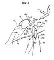
- a vehicle airbelt apparatus 40 relating to the present exemplary embodiment has, in addition to the first belt guide 21 of the first exemplary embodiment, a second belt guide 62 which can be accommodated in the seatback 26.
- the second belt guide 62 is configured to be accommodated within the seatback 26 at times of normal use, and so as to form a normal-time regulation guide hole 60, through which the occupant restraint webbing 16 passes between an upper end portion 62A thereof and an upper edge portion of the shoulder portion of the seatback 26, and which is configured to regulate the winding direction thereof.
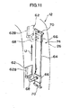
- a vertical sliding mechanism 74 is provided in the seatback 26, which, for example, enables sliding of the second belt guide 62 in the vertical direction of the seatback 26.
- the second belt guide 62 is structured so as to be lifted up by the inflation portion 18 and protrude upward at a time of inflation of the inflation portion 18, and form an inflation-time regulation belt guide.
- a rail 64 is provided extending along, for example, the vertical direction of the seatback 26.
- a leg portion 62B of the second belt guide 62 is mounted via, for example, an L-shaped mounting bracket 68 to a slider 66 which is slidable on the rail 64 within a range of upper and lower stoppers 70.
- the vertical sliding mechanism 74 is shown for one of the leg portions 62B, but it is desirable if the vertical sliding mechanism 74 is provided thus at the leg portions 62B at both sides, in order for the second belt guide 62 to be lifted up smoothly at a time of inflation of the inflation portion 18.
- the first belt guide 21 is provided adjacent and parallel to the front side of the second belt guide 62. Thus, deployment of the first belt guide 21 is not obstructed by the second belt guide 62.
- the first belt guide 21 need not be provided.
- the winding direction of the occupant restraint webbing 16 can be regulated by the normal-time regulation guide hole 21 A of the first belt guide 21 and the normal-time regulation guide hole 60 of the second belt guide 22, and a sense of application when the occupant 14 seated on the vehicle seat 12 has applied the occupant restraint webbing 16 is excellent.
- the inflator In the state in which the occupant restraint webbing 16 is applied, if a side impact is received from the side of the vehicle at which the occupant is sitting or such an impact is predicted, the inflator operates and, as shown in Fig. 10 , the inflation portion 18 inflates.
- the button 32 At the first belt guide 21, the button 32 is disengaged by inflation force of the inflation portion 18, and the upper pieces 21C and 21D move away from each other and deploy. Because the first belt guide 21 is provided adjacent to and parallel with the front side of the second belt guide 62, deployment of the first belt guide 21 will not be obstructed by the second belt guide 62.
- the slider 66 to which the leg portion 62B is mounted via the mounting bracket 68 slides in the direction of arrow U on the rail 64.
- the second belt guide 62 protrudes upward and goes into a non-accommodated state, and an inflation-time regulation guide hole 72 is broadened upward.
- This inflation-time regulation guide hole 72 is formed in an oblong shape which is long in the vertical direction.
- the cross-sectional shape of the inflation portion 18, which is regulated by the inflation-time regulation guide hole 72 is also an oblong shape which is long in the vertical direction, and the inflation portion 18 goes into a state which is inflated to a height position corresponding with the temple area 14S of the occupant 14.
- the winding direction of the occupant restraint webbing 16 can be regulated by the first belt guide 21 and the second belt guide 62 in an accommodated state at times of normal use, in addition to which, at the time of a side impact, an inflated shape of the inflation portion 18 can be regulated by the second belt guide 62 and the inflation portion 18 inflated to the height position corresponding with the temple area 14S of the occupant 14.
- inertial force of the cephalic region 14H of the occupant 14 in the vehicle lateral direction can be absorbed by the inflation portion 18.
- the inflation portion 18 is inflated to be oblong at a position corresponding with the temple area 14S, a broad region, for example, from the neck area 14N to the cephalic region 14H can be protected, and thus cephalic region protection characteristics are more excellent.
- the present exemplary embodiment an exemplary embodiment which uses the first belt guide 21 and the second belt guide 62 in combination has been described, but this is not a limitation.
- the second belt guide 62 alone may be used by itself, and the winding direction of the occupant restraint webbing 16 may be regulated by the normal-time regulation guide hole 60 of the second belt guide 62 at times of normal use.
- a volume of the inflation portion 18 can be set to be comparatively small. Accordingly, a folded thickness of the inflation portion 18 can be restrained. Therefore, operation characteristics of the occupant restraint webbing 16 at times of normal use will be excellent.
Landscapes
- Engineering & Computer Science (AREA)
- Mechanical Engineering (AREA)
- Textile Engineering (AREA)
- Air Bags (AREA)
- Automotive Seat Belt Assembly (AREA)
Claims (13)
- Pneumatische Sicherheitsgurtvorrichtung (10; 20; 30; 40) für ein Fahrzeug, die aufweist:ein Passagierrückhaltegurtband (16), welches mit einem Thoraxbereich (14B) eines Passagiers (14) übereinstimmt, der auf einem Fahrzeugsitz (12) sitzt;einen Aufblasabschnitt (18), der an dem Passagierrückhaltegurtband (16) vorgesehen ist und der zum Aufblaszeitpunkt mit einem Schädelbereich (14H) des Passagiers (14) übereinstimmt;eine Aufblasvorrichtung zum Zuführen von Gas für das Aufblasen des Aufblasabschnitts (18);einen Seitenaufprallsensor, der einen Seitenaufprall erfasst oder vorhersagt;eine Steuereinheit, die die Aufblasvorrichtung auf der Grundlage eines Ausgangssignals von dem Seitenaufprallsensor operieren lässt; undein Aufblaszeitpunktquerschnittsformregulierungselement (22; 24; 44, 46; 54; 62), durch welches das Passagierrückhaltegurtband (16) einschließlich des Aufblasabschnitts (18) verläuft, dadurch gekennzeichnet, dassdas Regulierungselement an einem Schulterabschnitt einer Rückenlehne (26) des Fahrzeugsitzes (12) vorgesehen ist und, indem das Aufblasen des Aufblasabschnitts (18) zu einer Außenseite in Fahrzeugquerrichtung zum Aufblaszeitpunkt des Aufblasabschnitts (18) hin beschränkt wird, eine Regulierung bewirkt, so dass eine Querschnittsform des Aufblasabschnitts (18) eine in vertikaler Richtung längliche Form hat.
- Pneumatische Sicherheitsgurtvorrichtung (10) für ein Fahrzeug gemäß Anspruch 1, wobei das Aufblaszeitpunktquerschnittsformregulierungselement (22) eine Aufblaszeitpunktregulierungsgurtführung ist, an welcher eine Aufblaszeitpunktregulierungsführungsöffnung (22A) vorgesehen ist, wobei die Führungsöffnung (22A) eine elliptische Form aufweist, die in vertikaler Richtung länger als in Fahrzeugquerrichtung ist, um die Querschnittsform des Aufblasabschnitts (18) zum Aufblaszeitpunkt zu regulieren, und ein oberes Ende (22B) der Aufblaszeitpunktregulierungsführungsöffnung (22A) so vorgesehen ist, dass sie sich an einer Stelle seitlich zu einer Kopfstütze (28) auf gleicher Höhe dazu erstreckt.
- Pneumatische Sicherheitsgurtvorrichtung (10) für ein Fahrzeug gemäß Anspruch 2, welche ferner eine Normalzeitpunktregulierungsgurtführung (21) aufweist, die in einem Bereich innerhalb der Aufblaszeitpunktregulierungsführungsöffnung (22A) angeordnet ist und an welcher eine Normalzeitpunktregulierungsführungsöffnung (21A) vorgesehen ist, welche eine Wicklungsrichtung des Passagierrückhaltegurtbands (16) reguliert, das zum Zeitpunkt eines normalen Gebrauchs durch diese verläuft, und welche durch Aufblasen des Aufblasabschnitts (18) erweitert wird.
- Pneumatische Sicherheitsgurtvorrichtung (40) für ein Fahrzeug gemäß Anspruch 1, wobei das Aufblaszeitpunktquerschnittsformregulierungselement (62) eine Gurtführung ist, welche zum Zeitpunkt eines normalen Gebrauchs in der Rückenlehne (26) untergebracht werden kann und an welcher eine Normalzeitpunktregulierungsführungsöffnung (21A) ausgebildet ist, um eine Wicklungsrichtung des Passagierrückhaltegurtbands (16) regulieren zu können, das in einem Unterbringungszustand zwischen ihrem oberen Endabschnitt (62A) und einem oberen Kantenabschnitt des Schulterabschnitts verläuft.
- Pneumatische Sicherheitsgurtvorrichtung (20) für ein Fahrzeug gemäß Anspruch 1, wobei das Aufblaszeitpunktquerschnittsformregulierungselement ein Paar von Führungshalbschalen (42, 46) ist, die an entsprechenden Lagerpunkte (34, 36) gelagert sind, die in Fahrzeugquerrichtung beabstandet vorgesehen sind, und die sich einander überlappen können und sich um die Lagerpunkte (34, 36) sich in entgegengesetzten Richtungen voneinander ausweiten können.
- Pneumatische Sicherheitsgurtvorrichtung (30) für ein Fahrzeug gemäß Anspruch 1, wobei das Aufblaszeitpunktquerschnittsformregulierungselement (54) eine Gurtführung ist, welche sich aufgrund des Aufblasens des Aufblasabschnitts (18) elastisch verformt oder sich um einen an dem Schulterabschnitt vorgesehenen Lagerpunkt (54A) dreht und sich innerhalb eines vorbestimmten Bereichs in eine Richtung weg von dem Schädelbereich (14H) des Passagiers (14) ausweiten kann.
- Pneumatische Sicherheitsgurtvorrichtung (10; 20; 30; 40) für ein Fahrzeug gemäß einem der Ansprüche 1 bis 6, wobei der Schulterabschnitt der Rückenlehne (26), an welcher das Aufblaszeitpunktquerschnittsformregulierungselement (22) vorgesehen ist, eine geneigte Fläche (42; 56) bildet, bei welcher ein Abstand von einem Mittelabschnitt des Fahrzeugsitzes (12) in Fahrzeugquerrichtung zu einem oberen Abschnitt des Schulterabschnitts kleiner als zu einem unteren Abschnitt des Schulterabschnitts ist.
- Pneumatische Sicherheitsgurtvorrichtung (10) für ein Fahrzeug gemäß Anspruch 1, wobei das Aufblaszeitpunktquerschnittsformregulierungselement (22) eine Aufblaszeitpunktregulierungsgurtführung ist, an welcher eine Aufblaszeitpunktregulierungsführungsöffnung (22A) vorgesehen ist, welche die Querschnittsform des Aufblasabschnitts (18) zum Aufblaszeitpunkt reguliert, und ein oberes Ende (22B) der Aufblaszeitpunktregulierungsführungsöffnung (22A) so vorgesehen ist, dass sie sich zu einer Stelle seitlich einer Kopfstütze (28) auf gleicher Höhe dazu erstreckt.
- Pneumatische Sicherheitsgurtvorrichtung (10) für ein Fahrzeug gemäß Anspruch 2, welche ferner eine Normalzeitpunktregulierungsgurtführung (21) aufweist, die neben und parallel zu der Aufblaszeitpunktregulierungsgurtführung (22) vorgesehen ist, und an welcher eine Normalzeitpunktregulierungsführungsöffnung (21A) vorgesehen ist, die eine Wicklungsrichtung des Passagierrückhaltegurtbandes (16) reguliert, das zum Zeitpunkt eines normalen Gebrauchs durch diese verläuft, und das durch Aufblasen des Aufblasabschnitts (18) aufgeweitet wird.
- Pneumatische Sicherheitsgurtvorrichtung (40) für ein Fahrzeug gemäß Anspruch 4, wobei ein vertikaler Gleitmechanismus an einem Fußabschnitt (62B) der Gurtführung (62) vorgesehen ist, so dass die Gurtführung (62) zum Aufblaszeitpunkt des Aufblasabschnitts (18) durch den Aufblasabschnitt (18) angehoben wird.
- Pneumatische Sicherheitsgurtvorrichtung (20) für ein Fahrzeug gemäß Anspruch 5, wobei die distalen Enden (44A, 46A) der Führungshalbschalen (44, 46) so aufgebaut sind, dass sie ineinander greifen, wenn die Gurtführung ausgefahren ist.
- Pneumatische Sicherheitsgurtvorrichtung (20) für ein Fahrzeug gemäß Anspruch 5, wobei die Führungshalbschalen (44, 46) zum Zeitpunkt eines normalen Gebrauchs in einem überlappten Zustand gehalten werden.
- Pneumatische Sicherheitsgurtvorrichtung (10; 20; 30; 40) für ein Fahrzeug gemäß einem der Ansprüche 1 bis 12, wobei der Aufblasabschnitt (18) zum Aufblaszeitpunkt auch mit dem Thoraxbereich (14B) des Passagiers (14) übereinstimmt.
Applications Claiming Priority (2)
| Application Number | Priority Date | Filing Date | Title |
|---|---|---|---|
| JP2006032068A JP4148266B2 (ja) | 2006-02-09 | 2006-02-09 | 車両用エアベルト装置 |
| PCT/JP2007/051940 WO2007091526A1 (ja) | 2006-02-09 | 2007-02-05 | 車両用エアベルト装置 |
Publications (3)
| Publication Number | Publication Date |
|---|---|
| EP1987991A1 EP1987991A1 (de) | 2008-11-05 |
| EP1987991A4 EP1987991A4 (de) | 2009-07-22 |
| EP1987991B1 true EP1987991B1 (de) | 2010-12-22 |
Family
ID=38345124
Family Applications (1)
| Application Number | Title | Priority Date | Filing Date |
|---|---|---|---|
| EP07708058A Not-in-force EP1987991B1 (de) | 2006-02-09 | 2007-02-05 | Pneumatische sicherheitsgurtvorrichtung für fahrzeug |
Country Status (10)
| Country | Link |
|---|---|
| US (1) | US8226115B2 (de) |
| EP (1) | EP1987991B1 (de) |
| JP (1) | JP4148266B2 (de) |
| KR (1) | KR100973764B1 (de) |
| CN (1) | CN101384455B (de) |
| BR (1) | BRPI0707601A2 (de) |
| CA (1) | CA2640050C (de) |
| DE (1) | DE602007011402D1 (de) |
| ES (1) | ES2358290T3 (de) |
| WO (1) | WO2007091526A1 (de) |
Cited By (2)
| Publication number | Priority date | Publication date | Assignee | Title |
|---|---|---|---|---|
| CN107444334A (zh) * | 2016-06-01 | 2017-12-08 | 福特全球技术公司 | 安全带的安全气囊总成 |
| DE102019208456A1 (de) * | 2019-06-11 | 2020-12-17 | Zf Friedrichshafen Ag | Reanimationshilfe an Bord eines Kraftfahrzeugs |
Families Citing this family (9)
| Publication number | Priority date | Publication date | Assignee | Title |
|---|---|---|---|---|
| JP4174515B2 (ja) * | 2006-02-09 | 2008-11-05 | トヨタ自動車株式会社 | 車両用エアベルト装置 |
| JP4569684B2 (ja) * | 2008-08-01 | 2010-10-27 | トヨタ自動車株式会社 | 車両用乗員拘束装置 |
| DE102009024558B4 (de) * | 2009-06-08 | 2023-02-02 | Mercedes-Benz Group AG | Verfahren zum Schützen eines Fahrzeuginsassen in einem Fahrzeugsitz eines Fahrzeugs |
| US8007001B2 (en) * | 2009-08-24 | 2011-08-30 | Pi-Fen Lin | Auxiliary inflatable belt device and auxiliary supporting belt device |
| DE102010053311A1 (de) * | 2010-12-02 | 2012-06-06 | Daimler Ag | Gurtband für einen Sicherheitsgurt eines Fahrzeugs |
| FR2991644B1 (fr) | 2012-06-06 | 2014-07-04 | Eurocopter France | Dispositif de protection d'un individu assis sur un siege, siege et vehicule |
| JP5850008B2 (ja) * | 2013-08-21 | 2016-02-03 | トヨタ自動車株式会社 | エアベルト装置 |
| US10179529B1 (en) * | 2017-11-14 | 2019-01-15 | Ford Global Technologies, Llc | Seatback with a seatbelt webbing retaining member with a releasably coupled end to allow the insertion of and to retain a webbing section of a seatbelt assembly |
| CN109606306B (zh) * | 2018-11-22 | 2021-08-03 | 江苏大学 | 一种可变宽式汽车安全带及其控制方法 |
Family Cites Families (20)
| Publication number | Priority date | Publication date | Assignee | Title |
|---|---|---|---|---|
| US3844001A (en) * | 1969-02-20 | 1974-10-29 | Holmberg Gote Eskil Yngve | Lock for a three-point safety belt for motor vehicles |
| US4348037A (en) * | 1980-06-03 | 1982-09-07 | Thiokol Corporation | Safety cushion attachable to belt-type restraints |
| JP2929616B2 (ja) | 1989-09-22 | 1999-08-03 | 東レ株式会社 | インクジェット染色用布帛の製造方法および染色法 |
| JP3057115B2 (ja) * | 1991-10-21 | 2000-06-26 | タカタ株式会社 | インフレータブルシートベルト装置 |
| JP3110881B2 (ja) | 1992-08-06 | 2000-11-20 | タカタ株式会社 | インフレータブルシートベルト装置 |
| JP3113081B2 (ja) | 1992-08-18 | 2000-11-27 | タカタ株式会社 | インフレータブルシートベルト装置 |
| DE69732294T2 (de) | 1996-07-02 | 2005-12-22 | Zodiac Automotive Us Inc., Tempe | Aufblasbares schlauchartiges rumpf-rückhaltesystem |
| JP3735436B2 (ja) | 1997-02-13 | 2006-01-18 | 本田技研工業株式会社 | ガス圧膨張式シートベルト |
| US6336656B1 (en) * | 1997-03-31 | 2002-01-08 | Simula, Inc. | Inflatable tubular torso restraint system with pivoting upper anchor point attachment |
| US5897169A (en) * | 1997-08-15 | 1999-04-27 | Chrysler Corporation | Seat belt webbing guide |
| US5829841A (en) | 1997-12-16 | 1998-11-03 | General Motors Coporation | Inflatable seat belt tensioner |
| JP2002527282A (ja) | 1998-10-09 | 2002-08-27 | シムラ インコーポレイテッド | 膨張式チューブ状シート身体拘束システム |
| DE19950951A1 (de) | 1999-10-22 | 2001-04-26 | Bayerische Motoren Werke Ag | Aufblasbarer Sicherheitsgurt |
| US6279945B1 (en) * | 2000-01-07 | 2001-08-28 | Autoliv Asp, Inc. | Guide fitting for inflatable vehicular safety belt |
| JP4458387B2 (ja) * | 2000-02-28 | 2010-04-28 | タカタ株式会社 | インフレータブルシートベルト装置 |
| US6547273B2 (en) * | 2000-10-05 | 2003-04-15 | Simula, Inc. | Inflatable seat restraint system using an inflation integrated inertia reel |
| US6520588B1 (en) * | 2000-11-16 | 2003-02-18 | Trw Vehicle Safety Systems Inc. | Seat belt guide |
| US20020171233A1 (en) * | 2001-05-18 | 2002-11-21 | Grace Gregory B. | System and method for vehicle occupant protection |
| JP4727081B2 (ja) * | 2001-07-30 | 2011-07-20 | 株式会社ニフコ | シートベルトガイド |
| JP4174515B2 (ja) * | 2006-02-09 | 2008-11-05 | トヨタ自動車株式会社 | 車両用エアベルト装置 |
-
2006
- 2006-02-09 JP JP2006032068A patent/JP4148266B2/ja not_active Expired - Fee Related
-
2007
- 2007-02-05 WO PCT/JP2007/051940 patent/WO2007091526A1/ja not_active Ceased
- 2007-02-05 US US12/278,788 patent/US8226115B2/en not_active Expired - Fee Related
- 2007-02-05 DE DE602007011402T patent/DE602007011402D1/de active Active
- 2007-02-05 CA CA2640050A patent/CA2640050C/en not_active Expired - Fee Related
- 2007-02-05 KR KR1020087021934A patent/KR100973764B1/ko not_active Expired - Fee Related
- 2007-02-05 ES ES07708058T patent/ES2358290T3/es active Active
- 2007-02-05 CN CN2007800049374A patent/CN101384455B/zh not_active Expired - Fee Related
- 2007-02-05 BR BRPI0707601-0A patent/BRPI0707601A2/pt not_active Application Discontinuation
- 2007-02-05 EP EP07708058A patent/EP1987991B1/de not_active Not-in-force
Cited By (3)
| Publication number | Priority date | Publication date | Assignee | Title |
|---|---|---|---|---|
| CN107444334A (zh) * | 2016-06-01 | 2017-12-08 | 福特全球技术公司 | 安全带的安全气囊总成 |
| CN107444334B (zh) * | 2016-06-01 | 2021-10-22 | 福特全球技术公司 | 安全带的安全气囊总成 |
| DE102019208456A1 (de) * | 2019-06-11 | 2020-12-17 | Zf Friedrichshafen Ag | Reanimationshilfe an Bord eines Kraftfahrzeugs |
Also Published As
| Publication number | Publication date |
|---|---|
| CA2640050A1 (en) | 2007-08-16 |
| CA2640050C (en) | 2011-05-31 |
| KR100973764B1 (ko) | 2010-08-04 |
| JP2007210431A (ja) | 2007-08-23 |
| ES2358290T3 (es) | 2011-05-09 |
| US8226115B2 (en) | 2012-07-24 |
| CN101384455B (zh) | 2011-07-20 |
| KR20080096693A (ko) | 2008-10-31 |
| CN101384455A (zh) | 2009-03-11 |
| EP1987991A4 (de) | 2009-07-22 |
| EP1987991A1 (de) | 2008-11-05 |
| WO2007091526A1 (ja) | 2007-08-16 |
| BRPI0707601A2 (pt) | 2011-05-10 |
| DE602007011402D1 (de) | 2011-02-03 |
| US20100164207A1 (en) | 2010-07-01 |
| WO2007091526A8 (ja) | 2008-10-23 |
| JP4148266B2 (ja) | 2008-09-10 |
Similar Documents
| Publication | Publication Date | Title |
|---|---|---|
| EP1987991B1 (de) | Pneumatische sicherheitsgurtvorrichtung für fahrzeug | |
| JP7243552B2 (ja) | ファーサイドエアバッグ装置 | |
| US8899619B2 (en) | Vehicle seat | |
| US8690187B2 (en) | Vehicle safety device | |
| US9919673B2 (en) | Vehicle occupant protection device | |
| US9132798B2 (en) | Seat-mounted airbag apparatus and vehicle seat | |
| US8038170B2 (en) | Vehicle occupant restraint apparatus | |
| CN101016041B (zh) | 车辆用空气安全带装置 | |
| JP5382199B2 (ja) | 車両用サイドエアバッグ装置 | |
| KR101807659B1 (ko) | 자동차의 파 사이드 에어백 장치 | |
| JP5799841B2 (ja) | 車両用シート | |
| CN102649415B (zh) | 乘员保护装置 | |
| JP2006264672A (ja) | 乗員拘束装置 | |
| JP2010083384A (ja) | 乗員拘束装置 | |
| JP4174514B2 (ja) | 車両用エアベルト装置 | |
| JP6751581B2 (ja) | 乗員保護装置 | |
| JP2022145179A (ja) | 車両用エアバッグ装置 | |
| JP2010105544A (ja) | 乗員拘束装置 | |
| WO2007069396A1 (ja) | 乗員拘束装置 | |
| JP5672222B2 (ja) | 車両用乗員拘束装置 | |
| JP2023010442A (ja) | サイドエアバッグ装置を搭載した車両用シート | |
| JP6744113B2 (ja) | 乗員保護装置 | |
| JP4816118B2 (ja) | 車両用エアベルト装置 | |
| JP4513719B2 (ja) | 車両用エアベルト装置 | |
| JP2010083431A (ja) | 乗員拘束装置 |
Legal Events
| Date | Code | Title | Description |
|---|---|---|---|
| PUAI | Public reference made under article 153(3) epc to a published international application that has entered the european phase |
Free format text: ORIGINAL CODE: 0009012 |
|
| 17P | Request for examination filed |
Effective date: 20080909 |
|
| AK | Designated contracting states |
Kind code of ref document: A1 Designated state(s): DE ES FR GB IT |
|
| DAX | Request for extension of the european patent (deleted) | ||
| RBV | Designated contracting states (corrected) |
Designated state(s): DE ES FR GB IT |
|
| A4 | Supplementary search report drawn up and despatched |
Effective date: 20090618 |
|
| RIC1 | Information provided on ipc code assigned before grant |
Ipc: B60R 21/18 20060101AFI20070919BHEP Ipc: B60R 22/26 20060101ALI20090612BHEP Ipc: B60R 22/28 20060101ALI20090612BHEP |
|
| 17Q | First examination report despatched |
Effective date: 20091201 |
|
| GRAP | Despatch of communication of intention to grant a patent |
Free format text: ORIGINAL CODE: EPIDOSNIGR1 |
|
| GRAS | Grant fee paid |
Free format text: ORIGINAL CODE: EPIDOSNIGR3 |
|
| GRAA | (expected) grant |
Free format text: ORIGINAL CODE: 0009210 |
|
| AK | Designated contracting states |
Kind code of ref document: B1 Designated state(s): DE ES FR GB IT |
|
| REG | Reference to a national code |
Ref country code: GB Ref legal event code: FG4D |
|
| REF | Corresponds to: |
Ref document number: 602007011402 Country of ref document: DE Date of ref document: 20110203 Kind code of ref document: P |
|
| REG | Reference to a national code |
Ref country code: DE Ref legal event code: R096 Ref document number: 602007011402 Country of ref document: DE Effective date: 20110203 |
|
| REG | Reference to a national code |
Ref country code: ES Ref legal event code: FG2A Ref document number: 2358290 Country of ref document: ES Kind code of ref document: T3 Effective date: 20110426 |
|
| PLBE | No opposition filed within time limit |
Free format text: ORIGINAL CODE: 0009261 |
|
| STAA | Information on the status of an ep patent application or granted ep patent |
Free format text: STATUS: NO OPPOSITION FILED WITHIN TIME LIMIT |
|
| 26N | No opposition filed |
Effective date: 20110923 |
|
| REG | Reference to a national code |
Ref country code: DE Ref legal event code: R097 Ref document number: 602007011402 Country of ref document: DE Effective date: 20110923 |
|
| REG | Reference to a national code |
Ref country code: GB Ref legal event code: 746 Effective date: 20121112 |
|
| REG | Reference to a national code |
Ref country code: DE Ref legal event code: R084 Ref document number: 602007011402 Country of ref document: DE Effective date: 20121115 |
|
| REG | Reference to a national code |
Ref country code: FR Ref legal event code: PLFP Year of fee payment: 9 |
|
| PGFP | Annual fee paid to national office [announced via postgrant information from national office to epo] |
Ref country code: DE Payment date: 20150127 Year of fee payment: 9 Ref country code: IT Payment date: 20150218 Year of fee payment: 9 Ref country code: ES Payment date: 20150113 Year of fee payment: 9 |
|
| PGFP | Annual fee paid to national office [announced via postgrant information from national office to epo] |
Ref country code: GB Payment date: 20150204 Year of fee payment: 9 Ref country code: FR Payment date: 20150210 Year of fee payment: 9 |
|
| REG | Reference to a national code |
Ref country code: DE Ref legal event code: R119 Ref document number: 602007011402 Country of ref document: DE |
|
| GBPC | Gb: european patent ceased through non-payment of renewal fee |
Effective date: 20160205 |
|
| REG | Reference to a national code |
Ref country code: FR Ref legal event code: ST Effective date: 20161028 |
|
| PG25 | Lapsed in a contracting state [announced via postgrant information from national office to epo] |
Ref country code: IT Free format text: LAPSE BECAUSE OF NON-PAYMENT OF DUE FEES Effective date: 20160205 |
|
| PG25 | Lapsed in a contracting state [announced via postgrant information from national office to epo] |
Ref country code: FR Free format text: LAPSE BECAUSE OF NON-PAYMENT OF DUE FEES Effective date: 20160229 Ref country code: GB Free format text: LAPSE BECAUSE OF NON-PAYMENT OF DUE FEES Effective date: 20160205 Ref country code: DE Free format text: LAPSE BECAUSE OF NON-PAYMENT OF DUE FEES Effective date: 20160901 |
|
| PG25 | Lapsed in a contracting state [announced via postgrant information from national office to epo] |
Ref country code: ES Free format text: LAPSE BECAUSE OF NON-PAYMENT OF DUE FEES Effective date: 20160206 |
|
| REG | Reference to a national code |
Ref country code: ES Ref legal event code: FD2A Effective date: 20181207 |