EP1987992B1 - Vorrichtung zum Führen des Riemens eines Sicherheitsgurts - Google Patents
Vorrichtung zum Führen des Riemens eines Sicherheitsgurts Download PDFInfo
- Publication number
- EP1987992B1 EP1987992B1 EP20070290561 EP07290561A EP1987992B1 EP 1987992 B1 EP1987992 B1 EP 1987992B1 EP 20070290561 EP20070290561 EP 20070290561 EP 07290561 A EP07290561 A EP 07290561A EP 1987992 B1 EP1987992 B1 EP 1987992B1
- Authority
- EP
- European Patent Office
- Prior art keywords
- tie
- fastener
- safety belt
- head
- elements
- Prior art date
- Legal status (The legal status is an assumption and is not a legal conclusion. Google has not performed a legal analysis and makes no representation as to the accuracy of the status listed.)
- Active
Links
Images

Classifications
-
- B—PERFORMING OPERATIONS; TRANSPORTING
- B60—VEHICLES IN GENERAL
- B60R—VEHICLES, VEHICLE FITTINGS, OR VEHICLE PARTS, NOT OTHERWISE PROVIDED FOR
- B60R22/00—Safety belts or body harnesses in vehicles
- B60R22/18—Anchoring devices
- B60R22/24—Anchoring devices secured to the side, door, or roof of the vehicle
-
- B—PERFORMING OPERATIONS; TRANSPORTING
- B60—VEHICLES IN GENERAL
- B60R—VEHICLES, VEHICLE FITTINGS, OR VEHICLE PARTS, NOT OTHERWISE PROVIDED FOR
- B60R22/00—Safety belts or body harnesses in vehicles
- B60R22/18—Anchoring devices
- B60R2022/1818—Belt guides
Definitions
- the present invention relates to a device for guiding the strap of a three-point safety belt along a concave portion of the bodywork of a motor vehicle, as well as a motor vehicle with such a safety belt and such device.
- Seat belts commonly used in motor vehicles are designed to restrain a passenger from three mounting points, two of these points, the lower mounting points, being located on either side of the seat base at which the seat belt is allocated and the third point, the upper mounting point, being located in height, on the bodywork, for example on the middle foot lining of a four-door car.
- This third mounting point is generally disposed at the height of the head of a standard passenger and is the starting point of the portion of the belt of the seat belt that is intended to hold the passenger's chest.
- the riser portion of the strap extends from the lower mounting point to the upper mounting point, follows suitably the shape of these and will not interfere with the occupant of the seat to which the seat belt is assigned. If, however, these elements have a curved shape, since the passenger compartment of the motor vehicle is wider at the passengers' shoulders than at the floor and at the ceiling, the rising portion of the strap no longer follows the shape of these elements, but follows a secant trajectory.
- the object of the invention is to propose a solution that allows a seat belt strap to be follow a curved shape of a bodywork element on which it is mounted.
- the solution must be easy to implement, especially in automatic assembly line.
- An adjustment device for a seat belt is known from the document US-A-4,799,737 .
- the object of the invention is achieved with a device for guiding a seat belt along a concave portion of the bodywork of a motor vehicle according to claim 1.
- the solution of the invention consists mainly, but not exclusively, in a piece having the shape of a loop or, apart from its elongated and non-circular shape, a hoop folded on itself and shaped to be fixed on the concave part of the bodywork.
- This arch is intended to be threaded onto the rising part of the strap intended to extend between a lower mounting point and an upper seatbelt mounting point and is further intended to be fixed at an intermediate position between the seats.
- this intermediate position to be determined according to the curved shape of the concave body part so as to maintain the strap closest to this bodywork element.
- This intermediate position generally corresponds to a cusp of the curve describing the shape of the concave part of the bodywork.
- the fastener is made of plastic material in the form of an almost completely closed loop intended to be threaded onto the belt of the seat belt during manufacture of the latter.
- the device of the invention consists mainly of a fastener having substantially the shape of an open loop, elongated or not. Thanks to the presence of a slot or opening in the periphery of the buckle, the belt of the safety belt can be introduced into the buckle after the manufacture of the safety belt and even when the safety belt is already mounted in a belt. vehicle. This arrangement makes it possible to replace the fastener if it broke, for example, during an accident of the vehicle.
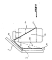
- the device of the invention is intended to guide a seat belt along a concave portion 2 of the bodywork of a motor vehicle.
- the safety belt is fixed in three points, namely in a first and a second lower points F1, F2 located in on both sides of a seat to which the belt is assigned, and at a higher point F3.
- the figure 1 represents in a simplified view the location of a device according to the invention on a curved part, in particular on a concave part, of the bodywork of a motor vehicle, as well as the effect obtained with this device.
- the middle foot in a four-door car, or a corresponding amount in a two-door car is a concave element, since the bodywork is wider at the same time. passenger shoulders to the floor and ceiling of the vehicle.
- the device according to the invention comprises a fastener 1 represented in detail on the Figures 2 and 3 and separable fixing means including first elements 11 are represented on the figure 3 and whose second elements 21 are represented on the figure 4 .
- the fastener 1 which is advantageously made of synthetic material by injection, comprises a body 10 having substantially the shape of an open loop or a bow whose ends are folded towards one another. The folded ends are extended by tabs 12 tending toward each other but leaving between their free ends an opening 13 through which the fastener 1 can be threaded onto the belt of the safety belt S.
- the tongues 12 may be of great length leaving between them a small opening which is sufficient to thread the clip 1 on the strap of the safety belt S and at the same time ensures that the clip is not lost between the moment of the manufacture of the belt and the mounting thereof in a motor vehicle.
- the tongues 12 may also be of short length leaving between them a large opening 13.
- the fastener 1 is also shaped to be immobilized on the part 2 of the body of a motor vehicle, for example on the lining of a central foot of the body.
- the device of the invention is provided with separable fixing means which comprise on the one hand first elements 11 formed projecting on the fastener 1 and secondly second elements 21 formed by punching in the part 2 of the body.
- the first elements 11 have a shape reminiscent of a mushroom, but with a head 111 and a rectangular body 112.
- the second elements 21 are formed by T-shaped openings, the width of the head 211 of the T corresponding to the width of the head 111 of the element 11 which must be introduced and the width of the body 212 of the T corresponding to the width of the body 112 of the element 11.
- the distance between the first elements 11 is given to that between the second elements 21, so that the fastener 1 can be immobilized on the part 2 of the body by insertion and locking of the first elements 11 in the second elements 21.
- the fastener 1 when it comes to immobilize the fastener 1 on the body part 2, the fastener 1 is presented with its first elements 11 in front of the wide portions 211 of the two punching 21 T, then the heads 111 of the elements 11 are introduced into the punchings and then the fastener 1 is moved in the direction of the arrow F indicated on the figure 3 so that the bodies 112 of the first elements 11 can engage in the less wide portion 212 punchings 21 and be locked in this manner.
- prestressed means 14 made in the form of two wings extending on either side of each of the first elements 11 and together forming a very obtuse angle wide open to the head 111.
- the height of the first elements 11, and more precisely the distance between the body 10 of the fastener 1 and the head 111 of each of the first elements 11, on the one hand, and the opening angle of the wings of the prestressed means 14 on the other hand, are determined in such a way that, when the fastener 1 is presented in front of the punchings 21, it is necessary to press on the fastener 1 to make the first elements 11 enter the punches 21 and thus overcome the prestressing generated by the wings of the prestressed means 14, before moving the fastener 1 in the direction of the arrow F.
- the rigidity of the material used for the production of the 1 in combination with an opening angle of the means 14 of the order of 160 ° will generally be sufficient to maintain the fastener 1 in a stable position when it comes to guide the belt of the safety belt S along the body 2.
- the vertical distance between the location of the punchings 21 and the upper mounting point of the safety belt will be determined for each type of vehicle according to geometric data of the body and the position of the seat, to which the safety belt is assigned, with respect to the body part 2.
Landscapes
- Engineering & Computer Science (AREA)
- Mechanical Engineering (AREA)
- Automotive Seat Belt Assembly (AREA)
Claims (7)
- Vorrichtung zur Führung eines Sicherheitsgurts (S) entlang eines konkaven Teils (2) der Karosserie eines Kraftfahrzeugs, wobei die Vorrichtung eine Befestigung (1) umfasst, die im Wesentlichen die Form einer Schnalle aufweist, die dazu angepasst ist, um auf dem Sicherheitsgurt (S) gleiten zu können, und um auf dem konkaven Teil (2) der Karosserie mit Hilfe von trennbaren Befestigungsmitteln (11, 21) blockiert werden zu können, dadurch gekennzeichnet, dass die trennbaren Befestigungsmittel (11, 21) erste Befestigungselemente (11) umfassen, die vorspringend auf der Befestigung (1) angebracht sind, wobei jedes von ihnen einen Kopf (111) und einen Körper (112) umfasst, der weniger breit als der Kopf (111) ist, und zweite Befestigungselemente (21), die auf dem konkaven Teil (2) der Karosserie angebracht sind, wobei jedes von ihnen aus einer T-förmigen Öffnung besteht, wobei die Breite des Kopfes (211) des T der Breite des Kopfes (111) des ersten entsprechenden Elements (11) entspricht und die Breite des Körpers (212) des T der Breite des Körpers (112) des entsprechenden ersten Elements entspricht.
- Vorrichtung nach Anspruch 1, dadurch gekennzeichnet, dass sie Mittel (14) umfasst, die dazu angepasst sind, um eine relative Spannung zwischen der Befestigung (1) und dem konkaven Teil (2) der Karosserie auszuüben, um die Befestigung (1) zu stabilisieren, wenn diese auf dem konkaven Teil (2) der Karosserie blockiert ist, wobei die Spannungsmittel (14) zwei Flügel umfassen, die zwischen sich einen stumpfen Öffnungswinkel einschließen, der gegen den Kopf (111) jedes der ersten Befestigungselemente (11) geöffnet ist.
- Vorrichtung nach Anspruch 2, dadurch gekennzeichnet, dass der Öffnungswinkel im Bereich von 160° liegt.
- Vorrichtung nach einem der Ansprüche 1 bis 3, dadurch gekennzeichnet, dass die Befestigung (1) auf ihrem Umfang mit einer Öffnung (13) versehen ist, die es ermöglicht, den Sicherheitsgurt (S) in die Befestigung (1) einzuführen.
- Vorrichtung nach Anspruch 4, dadurch gekennzeichnet, dass die Befestigung (1) mit langen Laschen (12) versehen ist, die eine kleine Öffnung (13) definieren.
- Vorrichtung nach Anspruch 4, dadurch gekennzeichnet, dass die Befestigung (1) mit kurzen Laschen (12) versehen ist, die eine große Öffnung (13) definieren.
- Kraftfahrzeug mit einem Sicherheitsgurt mit drei Befestigungspunkten, dadurch gekennzeichnet, dass es eine Vorrichtung nach einem der Ansprüche 1 bis 6 umfasst.
Priority Applications (2)
| Application Number | Priority Date | Filing Date | Title |
|---|---|---|---|
| EP20070290561 EP1987992B1 (de) | 2007-05-04 | 2007-05-04 | Vorrichtung zum Führen des Riemens eines Sicherheitsgurts |
| DE200760012663 DE602007012663D1 (de) | 2007-05-04 | 2007-05-04 | Vorrichtung zum Führen des Riemens eines Sicherheitsgurts |
Applications Claiming Priority (1)
| Application Number | Priority Date | Filing Date | Title |
|---|---|---|---|
| EP20070290561 EP1987992B1 (de) | 2007-05-04 | 2007-05-04 | Vorrichtung zum Führen des Riemens eines Sicherheitsgurts |
Publications (2)
| Publication Number | Publication Date |
|---|---|
| EP1987992A1 EP1987992A1 (de) | 2008-11-05 |
| EP1987992B1 true EP1987992B1 (de) | 2011-02-23 |
Family
ID=38521752
Family Applications (1)
| Application Number | Title | Priority Date | Filing Date |
|---|---|---|---|
| EP20070290561 Active EP1987992B1 (de) | 2007-05-04 | 2007-05-04 | Vorrichtung zum Führen des Riemens eines Sicherheitsgurts |
Country Status (2)
| Country | Link |
|---|---|
| EP (1) | EP1987992B1 (de) |
| DE (1) | DE602007012663D1 (de) |
Families Citing this family (4)
| Publication number | Priority date | Publication date | Assignee | Title |
|---|---|---|---|---|
| US9308889B1 (en) * | 2014-11-11 | 2016-04-12 | Fca Us Llc | Shoulder belt guide with stow feature |
| DE102015101643B4 (de) | 2015-02-05 | 2018-03-29 | Lenz, Kämper GmbH & Co. KG | Gurtführungseinrichtung für Kraftfahrzeuge sowie Führungseinheit hierfür |
| DE102021111989A1 (de) * | 2020-05-19 | 2021-11-25 | Illinois Tool Works Inc. | Gurtführungsvorrichtung für einen Passagierrückhaltegurt eines Kraftfahrzeugs |
| ES3035715A1 (es) * | 2024-03-05 | 2025-09-08 | Seat Sa | Revestimiento interior de un montante de un vehículo, conjunto montante que lo comprende y método de montaje |
Family Cites Families (4)
| Publication number | Priority date | Publication date | Assignee | Title |
|---|---|---|---|---|
| DE2545890A1 (de) * | 1975-10-14 | 1977-04-21 | Bayerische Motoren Werke Ag | Rueckhalteeinrichtung mit einem aufwickelbaren sicherheitsgurt fuer kraftfahrzeuginsassen |
| JPS57191145A (en) * | 1981-05-19 | 1982-11-24 | Nissan Motor Co Ltd | Webbing guide device |
| US4799737A (en) * | 1987-03-16 | 1989-01-24 | Greene Marc B | Shoulder belt adjuster |
| US5372382A (en) * | 1993-04-12 | 1994-12-13 | Ford Motor Company | Seat belt webbing guide assembly |
-
2007
- 2007-05-04 EP EP20070290561 patent/EP1987992B1/de active Active
- 2007-05-04 DE DE200760012663 patent/DE602007012663D1/de active Active
Also Published As
| Publication number | Publication date |
|---|---|
| DE602007012663D1 (de) | 2011-04-07 |
| EP1987992A1 (de) | 2008-11-05 |
Similar Documents
| Publication | Publication Date | Title |
|---|---|---|
| EP1987992B1 (de) | Vorrichtung zum Führen des Riemens eines Sicherheitsgurts | |
| FR3102437A1 (fr) | Support en tôle pour enrouleur de ceinture de sécurité arrière d’un véhicule automobile | |
| EP3034363A1 (de) | Halterung für hinteren sicherheitsgurtaufroller, die eine platte mit einer angefügten versteifung umfasst | |
| EP2900521B1 (de) | Vorrichtung zur installation eines kabelkanals an einem karosserieteil eines kraftfahrzeugs | |
| EP4136706B1 (de) | Fahrzeug mit einer v2x-antenne auf seiner rückwand | |
| EP2199630B1 (de) | Haltestruktur für ein Befestigungselement | |
| FR2883525A1 (fr) | Appui-tete avec structure porteuse et corps d'appui | |
| EP3233585B1 (de) | Gurtaufrollerhalterung eines sicherheitsgurtes hinten in einem kraftfahrzeug | |
| JP6576634B2 (ja) | ガイドアンカー及びシートベルト装置 | |
| EP3233584B1 (de) | Transversal verstärkte befestigung eines sicherheitsgurtaufrollers auf der mittigen säule eines fahrzeugs | |
| JP5165525B2 (ja) | 車両用内装材およびその取付け方法 | |
| FR2982558A3 (fr) | Logement de rangement pour un pene de ceinture de securite | |
| EP3792118B1 (de) | Verkleidungselement für lenksäule eines kraftfahrzeugs | |
| FR2993216A1 (fr) | Element d'ancrage pour la fixation amovible d'un siege enfant sur la banquette arriere d'un vehicule automobile. | |
| EP2785563B1 (de) | Anordnung einer lateralen auskleidung für einen gepäckraum | |
| EP2670631B1 (de) | Anordnung und verfahren zum halten eines stossfängers und fahrzeug mit einer derartigen anordnung | |
| FR2616726A1 (fr) | Dispositif d'ancrage pour ceinture de securite | |
| FR2928320A1 (fr) | Systeme de fixation d'un enrouleur de securite et d'autres organes de securite a une partie rigide de la caisse d'un vehicule automobile. | |
| EP2132062B1 (de) | Baugruppe zur anbringung eines sicherheitsbeutelmoduls an einer mechanisch resistenten struktur eines armaturenbretts | |
| WO2007036664A1 (fr) | Dispositif et procede pour fixer une garniture sur le montant de baie d'un vehicule automobile | |
| EP3160802B1 (de) | Kraftfahrzeugsitz mit einer gurtführung für einen sicherheitsgurt | |
| EP2165892B1 (de) | Gurtführung für Sicherheitsgurt und Vorrichtung zum Befestigen dieser Gurtführung an einem mittleren Fuß eines Kraftfahrzeugs | |
| FR3067673B1 (fr) | Agencement d'un airbag rideau sur une caisse de vehicule | |
| EP3287324B1 (de) | Montage einer verkleidungsstruktur in ein öffnungselement in einer einlagewand eines fahrzeugs, die mit einem m-förmigen halteelement ausgestattet ist | |
| EP2036451B1 (de) | Nicht projektierbarer Schnappriegel eines Gurts mit Gehäuse für einen Dreipunktesicherheitsgurt eines Kraftfahrzeugs |
Legal Events
| Date | Code | Title | Description |
|---|---|---|---|
| PUAI | Public reference made under article 153(3) epc to a published international application that has entered the european phase |
Free format text: ORIGINAL CODE: 0009012 |
|
| AK | Designated contracting states |
Kind code of ref document: A1 Designated state(s): AT BE BG CH CY CZ DE DK EE ES FI FR GB GR HU IE IS IT LI LT LU LV MC MT NL PL PT RO SE SI SK TR |
|
| AX | Request for extension of the european patent |
Extension state: AL BA HR MK RS |
|
| 17P | Request for examination filed |
Effective date: 20090406 |
|
| AKX | Designation fees paid |
Designated state(s): DE FR |
|
| 17Q | First examination report despatched |
Effective date: 20100503 |
|
| GRAP | Despatch of communication of intention to grant a patent |
Free format text: ORIGINAL CODE: EPIDOSNIGR1 |
|
| GRAS | Grant fee paid |
Free format text: ORIGINAL CODE: EPIDOSNIGR3 |
|
| GRAA | (expected) grant |
Free format text: ORIGINAL CODE: 0009210 |
|
| AK | Designated contracting states |
Kind code of ref document: B1 Designated state(s): DE FR |
|
| REF | Corresponds to: |
Ref document number: 602007012663 Country of ref document: DE Date of ref document: 20110407 Kind code of ref document: P |
|
| REG | Reference to a national code |
Ref country code: DE Ref legal event code: R096 Ref document number: 602007012663 Country of ref document: DE Effective date: 20110407 |
|
| PLBE | No opposition filed within time limit |
Free format text: ORIGINAL CODE: 0009261 |
|
| STAA | Information on the status of an ep patent application or granted ep patent |
Free format text: STATUS: NO OPPOSITION FILED WITHIN TIME LIMIT |
|
| 26N | No opposition filed |
Effective date: 20111124 |
|
| REG | Reference to a national code |
Ref country code: DE Ref legal event code: R097 Ref document number: 602007012663 Country of ref document: DE Effective date: 20111124 |
|
| REG | Reference to a national code |
Ref country code: FR Ref legal event code: PLFP Year of fee payment: 10 |
|
| REG | Reference to a national code |
Ref country code: FR Ref legal event code: PLFP Year of fee payment: 11 |
|
| REG | Reference to a national code |
Ref country code: FR Ref legal event code: PLFP Year of fee payment: 12 |
|
| PGFP | Annual fee paid to national office [announced via postgrant information from national office to epo] |
Ref country code: DE Payment date: 20250602 Year of fee payment: 19 |
|
| PGFP | Annual fee paid to national office [announced via postgrant information from national office to epo] |
Ref country code: FR Payment date: 20250513 Year of fee payment: 19 |